Wireless Communication and Management System for E-Bike Dynamic Inductive Power Transfer Lanes

 , ,
, ,  and
and
Abstract
:1. Introduction
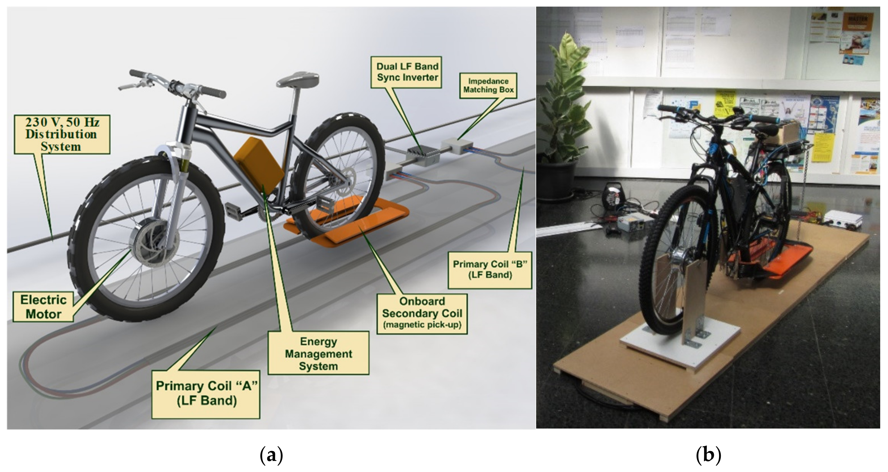
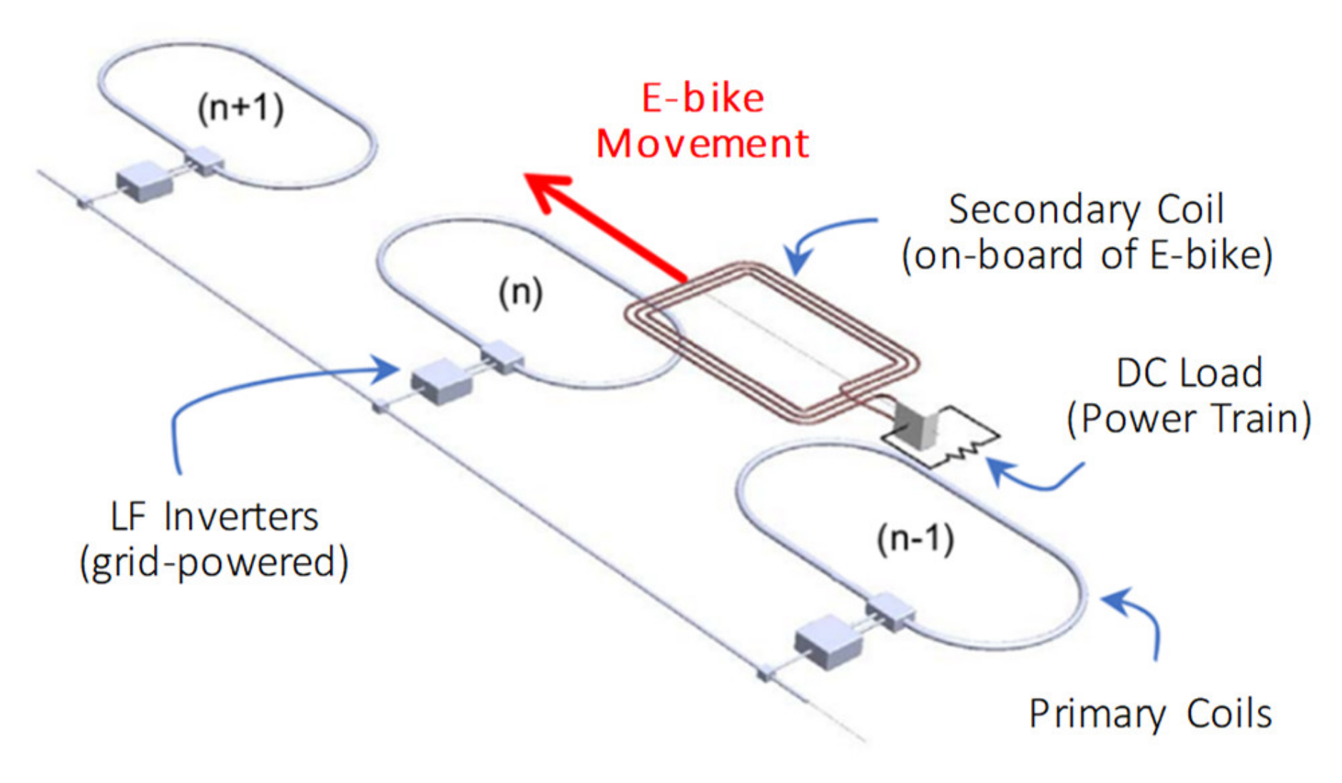
2. System Design
2.1. Functional Requirements
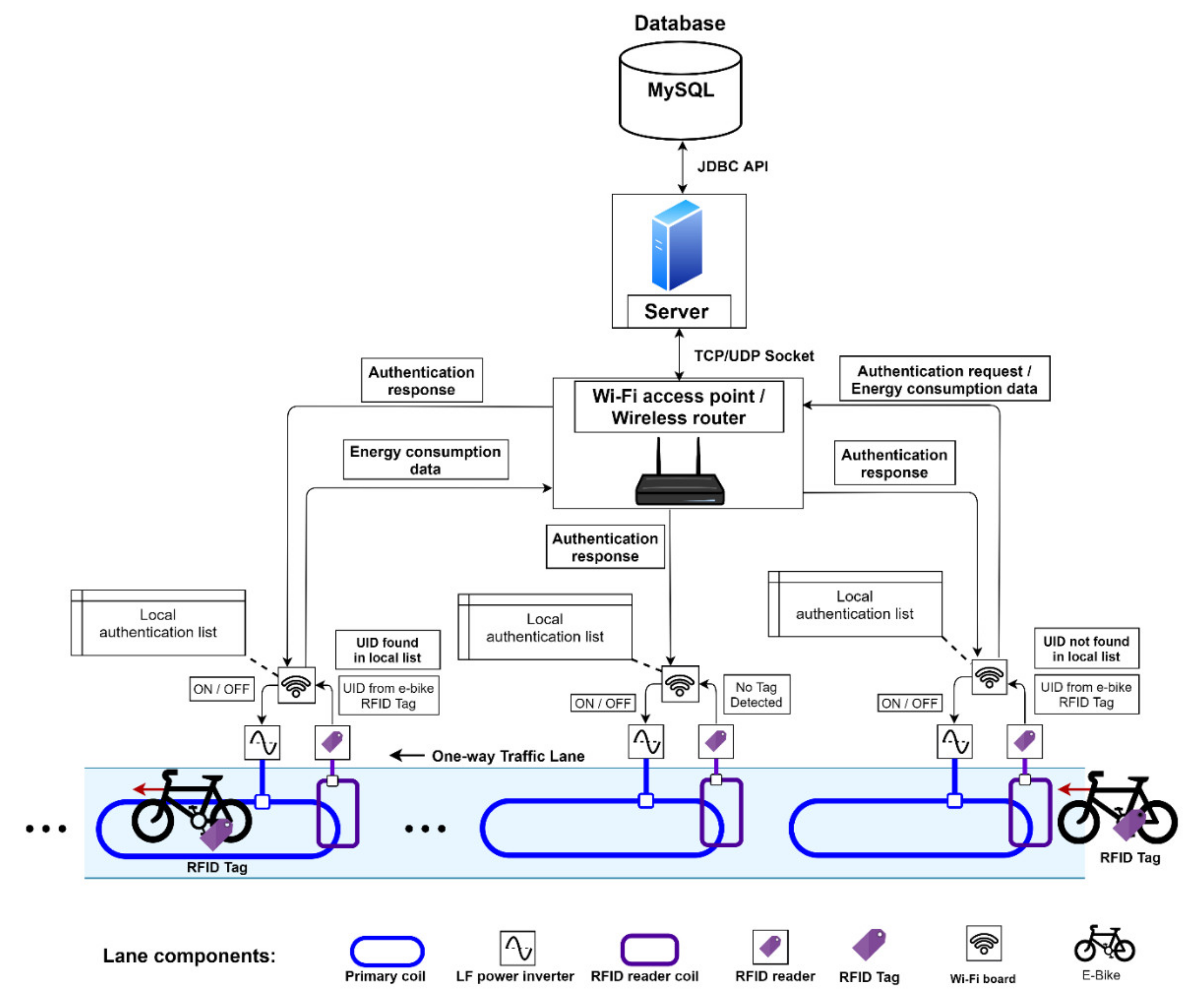
2.2. System Architecture
3. System Development
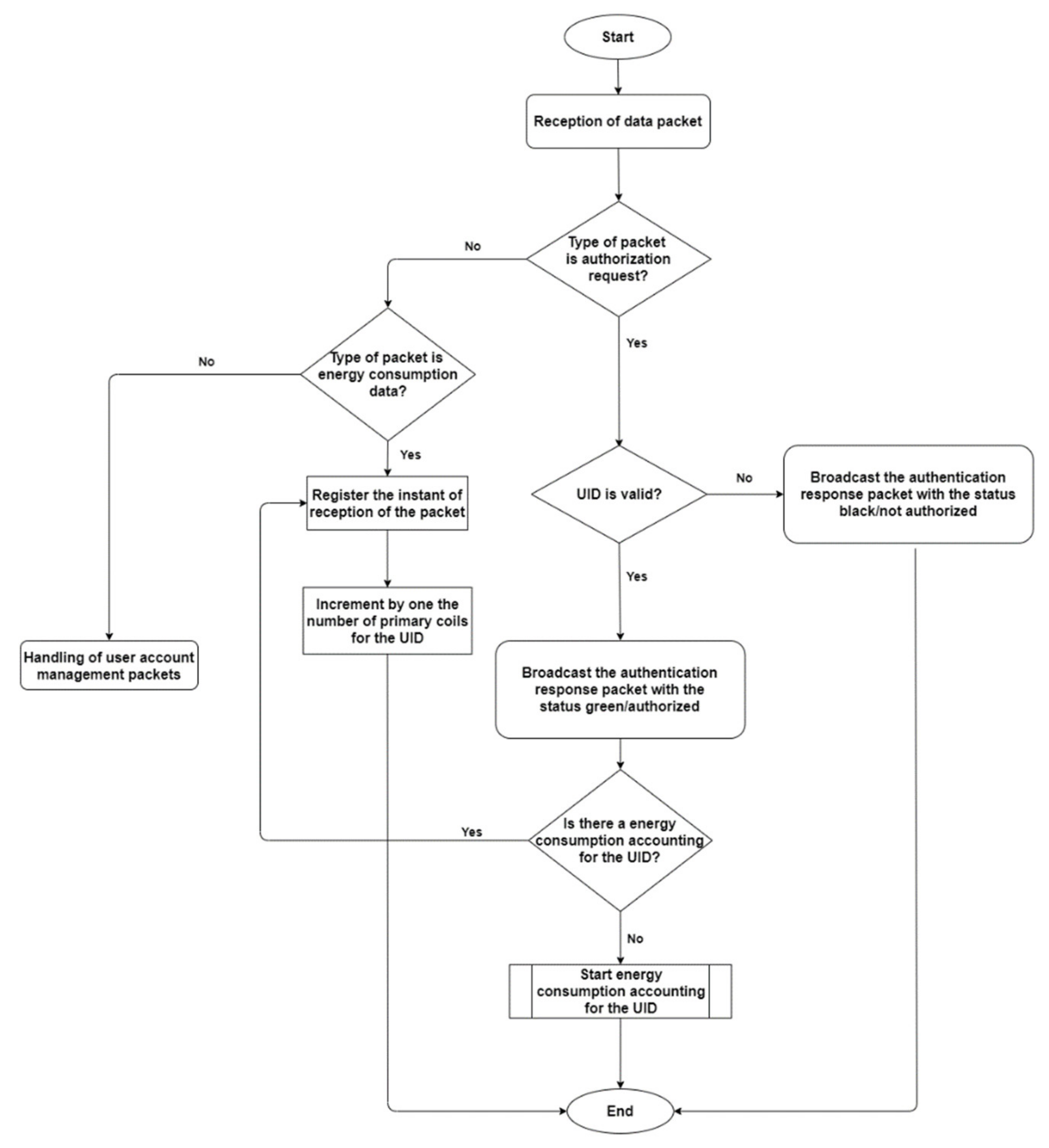
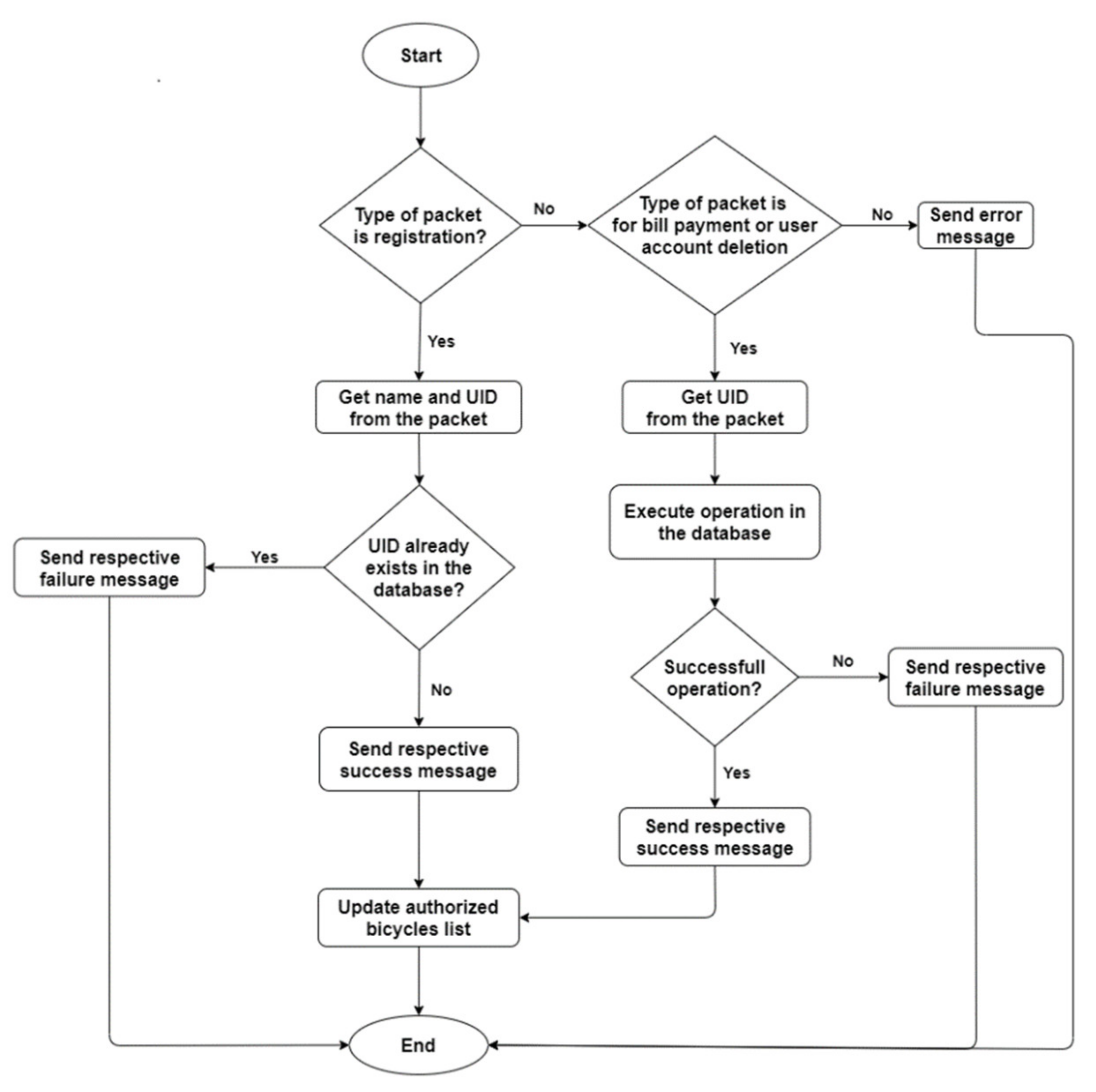
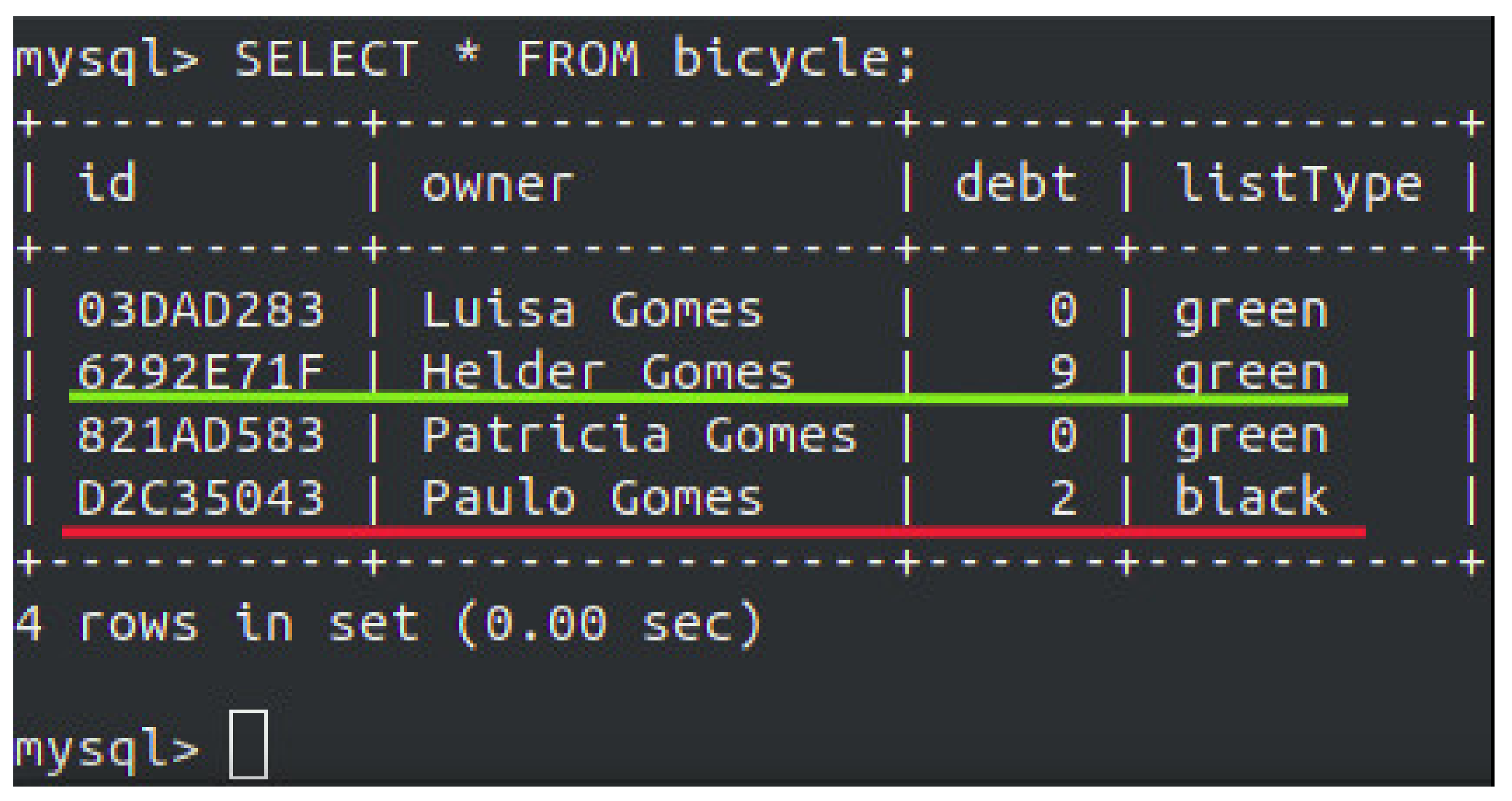
3.1. Server and Database
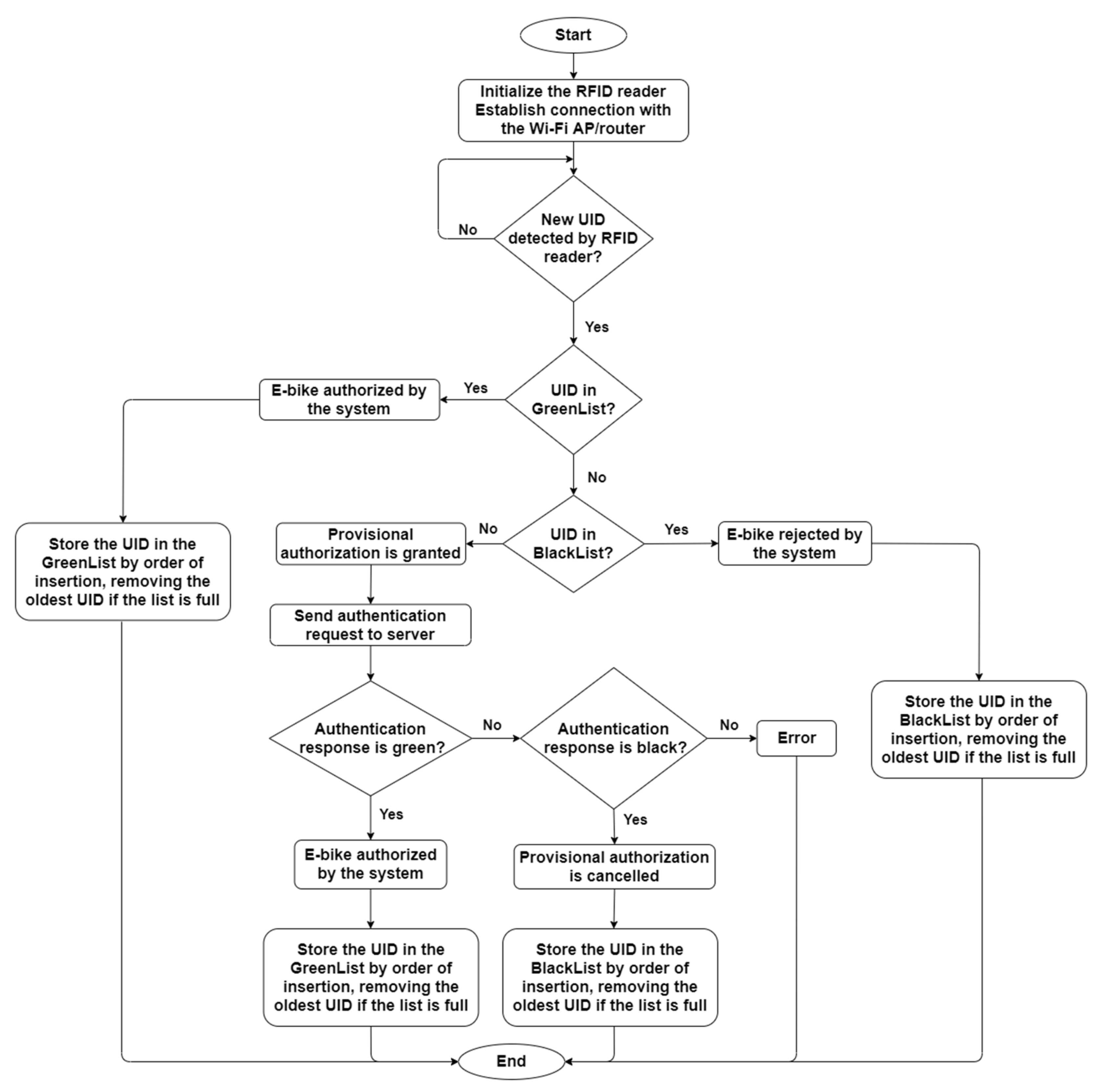
3.2. Embedded Boards
3.3. Data Packets Structure
4. Experimental Results
4.1. Quality of Service
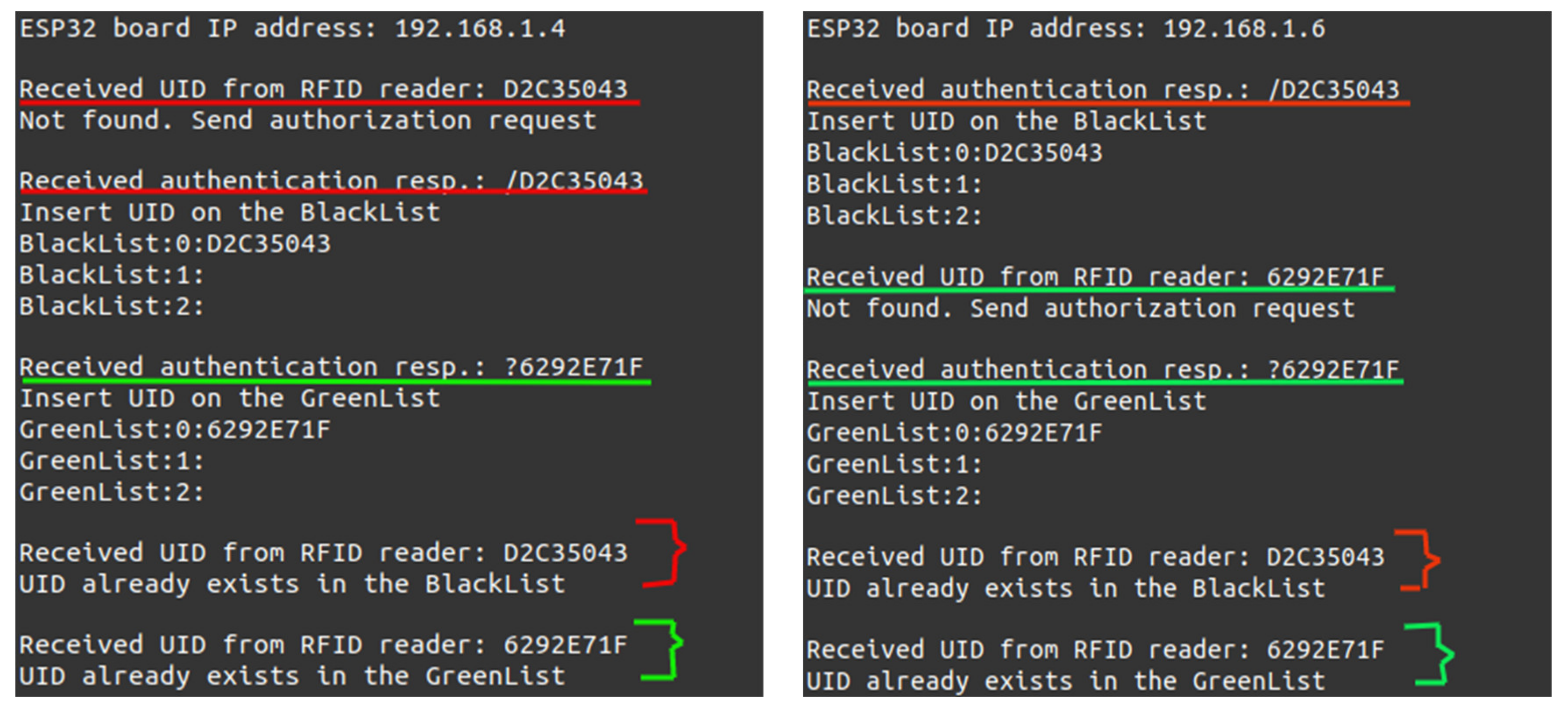
4.2. Functional Requirements
5. Conclusions and Future Work
Author Contributions
Funding
Conflicts of Interest
References
- Cardoso, L.A.L.; Martinez, M.C.; Melendez, A.A.N.; Afonso, J.L. Dynamic inductive power transfer lane design for e-bikes. In Proceedings of the IEEE 19th International Conference on Intelligent Transportation Systems (ITSC), Rio de Janeiro, Brazil, 1–4 November 2016; pp. 2307–2312. [Google Scholar]
- Lukic, S.; Pantic, Z. Cutting the Cord: Static and Dynamic Inductive Wireless Charging of Electric Vehicles. IEEE Electrif. Mag. 2013, 1, 57–64. [Google Scholar] [CrossRef]
- Song, K.; Koh, K.E.; Zhu, C.; Jiang, J.; Wang, C.; Huang, X. A Review of Dynamic Wireless Power Transfer for In-Motion Electric Vehicles. In Wireless Power Transfer; Coca, E., Ed.; IntechOpen: Rijeka, Croatia, 2016. [Google Scholar]
- Deng, B.; Jia, B.; Zhang, Z. Dynamic Wireless Charging for Roadway-Powered Electric Vehicles: A Comprehensive Analysis and Design. Prog. Electromagn. Res. C 2016, 69, 1–10. [Google Scholar] [CrossRef] [Green Version]
- Patil, D.; McDonough, M.K.; Miller, J.M.; Fahimi, B.; Balsara, P.T. Wireless Power Transfer for Vehicular Applications: Overview and Challenges. IEEE Trans. Transp. Electrif. 2018, 4, 3–37. [Google Scholar] [CrossRef]
- Laporte, S.; Coquery, G.; Deniau, V.; De Bernardinis, A.; Hautière, N. Dynamic Wireless Power Transfer Charging Infrastructure for Future EVs: From Experimental Track to Real Circulated Roads Demonstrations. World Electr. Veh. J. 2019, 10, 84. [Google Scholar] [CrossRef] [Green Version]
- Cirimele, V.; Diana, M.; Bellotti, F.; Berta, R.; El Sayed, N.; Kobeissi, A.; Colussi, J. The fabric ICT platform for managing wireless dynamic charging road lanes. IEEE Trans. Veh. Technol. 2020, 69, 2501–2512. [Google Scholar] [CrossRef]
- COHDA Wireless. Available online: http://www.cohdawireless.com/ (accessed on 1 June 2020).
- Cardoso, L.A.L.; Afonso, J.L.; Martinez, M.C.; Meléndez, A.A.N. RFID-Triggered Power Activation for Smart Dynamic Inductive Wireless Power Transfer. In Proceedings of the IECON-The Annual Conference of the IEEE Industrial Electronics Society (IES), Beijing, China, 29 October–1 November 2017. [Google Scholar]
- EU 168/2013, Regulation (EU) No. 168/2013 of the European Parliament and of the Council of 15 January 2013 on the Approval and Market Surveillance of Two- or Three-wheel Vehicles and Quadricycles. Available online: https://eur-lex.europa.eu/legal-content/EN/ALL/?uri=CELEX%3A32013R0168 (accessed on 2 June 2020).
- Association Française de Normalisation (AFNOR). European Standard NF EN 15194; European Committee for Standardization (CEN): Brussels, Belgium, 2017. [Google Scholar]
- Jamaluddin, A.; Harjunowibowo, D.; Rochim, M.A.; Mahadmadi, F.; Kakanita, H.B.; Laksono, P.W. Implementation of RFID on Computer Based Test (RF-CBT) System. In Proceedings of the IEEE International Conference on Electric Vehicular Technology and Industrial, Mechanical, Electrical and Chemical Engineering (ICEVT & IMECE), Surakarta, Indonesia, 4–5 November 2015; pp. 153–156. [Google Scholar]
- Hiertz, G.R.; Denteneer, D.; Stibor, L.; Zang, Y.; Costa, X.P.; Walke, B. The IEEE 802.11 universe. IEEE Commun. Mag. 2010, 48, 62–70. [Google Scholar] [CrossRef]
- Law, D.; Dove, D.; D’Ambrosia, J.; Hajduczenia, M.; Laubach, M.; Carlson, S. Evolution of Ethernet standards in the IEEE 802.3 working group. IEEE Commun. Mag. 2013, 51, 88–96. [Google Scholar] [CrossRef]
- Siep, T.M.; Gifford, I.C.; Braley, R.C.; Heile, R.F. Paving the way for personal area network standards: An overview of the IEEE P802.15 Working Group for Wireless Personal Area Networks. IEEE Pers. Commun. 2000, 7, 37–43. [Google Scholar] [CrossRef]
- Bluetooth SIG, Version 5.0; Specification of the Bluetooth System. Available online: https://www.mouser.it/pdfdocs/bluetooth-Core-v50.pdf (accessed on 14 May 2020).
- Baronti, P.; Pillai, P.; Chook, V.W.; Chessa, S.; Gotta, A.; Hu, Y.F. Wireless sensor networks: A survey on the state of the art and the 802.15.4 and ZigBee standards. Comput. Commun. 2007, 30, 1655–1695. [Google Scholar] [CrossRef]
- Expressif Systems, “ESP32-WROOM-32”, V2.8 Datasheet. 2019. Available online: https://www.espressif.com/sites/default/files/documentation/esp32-wroom-32d_esp32-wroom-32u_datasheet_en.pdf (accessed on 13 May 2020).
- NXP Semiconductors N.V. “MFRC522 Standard Performance MIFARE and NTAGfrontend”, 112139 Datasheet. Available online: https://www.nxp.com/docs/en/data-sheet/MFRC522.pdf (accessed on 27 April 2016).
- IEEE. 802.11-2016—IEEE Standard for Information Technology—Telecommunications and Information Exchange between Systems Local and Metropolitan Area Networks—Specific Requirements-Part 11: Wireless LAN Medium Access Control (MAC) and Physical Layer (PHY) Specifications; IEEE: Piscataway, NJ, USA, 2016. [Google Scholar]


| Parameter | Value |
|---|---|
| Minimum delay | 4.5 ms |
| Mean delay | 104.2 ms |
| Maximum delay | 211.6 ms |
| Standard deviation | 68.1 ms |
| Delivery ratio | 99.8% |
© 2020 by the authors. Licensee MDPI, Basel, Switzerland. This article is an open access article distributed under the terms and conditions of the Creative Commons Attribution (CC BY) license (http://creativecommons.org/licenses/by/4.0/).
Share and Cite
Afonso, J.A.; Duarte, H.G.; Cardoso, L.A.L.; Monteiro, V.; Afonso, J.L. Wireless Communication and Management System for E-Bike Dynamic Inductive Power Transfer Lanes. Electronics 2020, 9, 1485. https://0-doi-org.brum.beds.ac.uk/10.3390/electronics9091485
Afonso JA, Duarte HG, Cardoso LAL, Monteiro V, Afonso JL. Wireless Communication and Management System for E-Bike Dynamic Inductive Power Transfer Lanes. Electronics. 2020; 9(9):1485. https://0-doi-org.brum.beds.ac.uk/10.3390/electronics9091485
Chicago/Turabian StyleAfonso, Jose A., Helder G. Duarte, Luiz A. Lisboa Cardoso, Vitor Monteiro, and Joao L. Afonso. 2020. "Wireless Communication and Management System for E-Bike Dynamic Inductive Power Transfer Lanes" Electronics 9, no. 9: 1485. https://0-doi-org.brum.beds.ac.uk/10.3390/electronics9091485