Article

Improvement of Steam Injection Processes Through Nanotechnology: An Approach through in Situ Upgrading and Foam Injection

1
Grupo de Investigación en Fenómenos de Superficie—Michael Polanyi, Departamento de Procesos y Energía, Facultad de Minas, Universidad Nacional de Colombia, Medellín 050034, Colombia
2
Grupo de Yacimientos de Hidrocarburos, Departamento de Procesos y Energía, Facultad de Minas, Universidad Nacional de Colombia, Medellín 050034, Colombia
3
Enhanced Oil Recovery (EOR) Research Center, IOR/EOR Research Institute, Shiraz University, Shiraz 71345, Iran
*
Authors to whom correspondence should be addressed.
Submission received: 15 November 2019 / Revised: 29 November 2019 / Accepted: 2 December 2019 / Published: 6 December 2019
(This article belongs to the Special Issue Thermal and Thermal-Solvent Methods for Oil Recovery)

Abstract

:
This study aims to evaluate a high-performance nanocatalyst for upgrading of extra-heavy crude oil recovery and at the same time evaluate the capacity of foams generated with a nanofluid to improve the sweeping efficiency through a continuous steam injection process at reservoir conditions. CeO2±δ nanoparticles functionalized with mass fractions of 0.89% and 1.1% of NiO and PdO, respectively, were employed to assist the technology and achieve the oil upgrading. In addition, silica nanoparticles grafted with a mass fraction of 12% polyethylene glycol were used as an additive to improve the stability of an alpha-olefin sulphonate-based foam. The nanofluid formulation for the in situ upgrading process was carried out through thermogravimetric analysis and measurements of zeta potential during eight days to find the best concentration of nanoparticles and surfactant, respectively. The displacement test was carried out in different stages, including, (i) basic characterization, (ii) steam injection in the absence of nanofluids, (iii) steam injection after soaking with nanofluid for in situ upgrading, (iv) N2 injection, and (v) steam injection after foaming nanofluid. Increase in the oil recovery of 8.8%, 3%, and 5.5% are obtained for the technology assisted by the nanocatalyst-based nanofluid, after the nitrogen injection, and subsequent to the thermal foam injection, respectively. Analytical methods showed that the oil viscosity was reduced 79%, 77%, and 31%, in each case. Regarding the asphaltene content, with the presence of the nanocatalyst, it decreased from 28.7% up to 12.9%. Also, the American Petroleum Institute (API) gravity values increased by up to 47%. It was observed that the crude oil produced after the foam injection was of higher quality than the crude oil without treatment, indicating that the thermal foam leads to a better swept of the porous medium containing upgraded oil.

1. Introduction

One of the biggest problems in the use of heavy (HO) and extra-heavy crude oils (EHO) as an energy source is their low quality [1,2,3], which leads to production, transportation, and refining operations that require high energy and economic investments [4,5,6]. HO and EHO generally have a large percentage of heavy components, such as resins and asphaltenes, which reduce the API gravity and increase the oil viscosity. Besides, HO and EHO have a low hydrogen/carbon ratio (H/C) and generally produce more than 50% by weight of residue with boiling points above 500 °C, which makes the conversion into light hydrocarbons difficult [7,8]. HO and EHO hold high contents of metals such as Fe, Ni, and V, as well as heteroatoms such as S, O, and N, which in the refining process lead to the generation of compounds harmful to the environment [2,9,10].
In this sense, multiple techniques have been developed to increase the productivity of these reservoirs through in situ oil upgrading [11,12]. Thermal processes, which involve heat injection into the reservoir, include techniques such as hot water injection [13], steam-assisted gravity drainage (SAGD) [14,15,16], continuous and cyclic steam stimulation (CSS) [17,18], in situ combustion (ISC) [19,20], oxidative processes at low temperatures, aquathermolysis [21], and cracking injection processes (thermolysis) [22]. Among these, the steam injection has significant advantages due to its ease to heat the reservoir using water vapor [21,23]. Nevertheless, different problems, such as steam channeling [24], loss of energy [25], low thermal conductivity, and steam condensation are associated with this type of process that reduces the efficiency and makes the operation economically expensive [26]. Hence, it is important to implement new technologies to optimize steam injection processes and increase the recovery factor in heavy oil reservoirs [27].
Recently, nanotechnology appears as a complementary technique for assisting steam injection processes. The small size of the nanoparticles (1–100 nm) favors its injection in the porous medium with low risk of blockage. The properties of nanoparticles such as high thermal conductivity [28], excellent thermal stability [29], high catalytic activity [30], and selectivity towards heavy hydrocarbons [31], can increase the efficiency of steam injection processes. One approach is related to the use of catalytic nanoparticles for the upgrading of HO and EHO. Different functionalized and non-functionalized nanoparticulate materials have been widely studied to evaluate their adsorptive and catalytic effect over the decomposition of heavy oil fractions.
The functionalized materials involve the use of a supporting nanoparticle such as SiO2 [32], Al2O3 [33], TiO2 [34], CeO2 [35] that are generally responsible for the high affinity for heavy hydrocarbons. These supports are functionalized with smaller nanoparticles/nanocrystals on its surface, commonly of metal oxides such as NiO, PdO, Fe3O4, and Co3O4, [32,35,36,37,38,39,40] which act as an active phase to increase the catalytic activity of the composite nanomaterial. It has been demonstrated that these nanoparticles can decompose the heaviest fraction of crude oil at temperatures that can be found in a steam injection process (< 250 °C), improving permanently its quality, by increasing the API gravity and reducing the viscosity and asphaltene content [17,35]. The evaluation of this technology under dynamic conditions will guarantee the success of its application under field conditions. However, there are few studies focused on the use of nanocatalyst under these conditions in thermal-enhanced oil recovery processes. Yuan et al. [41] employed nickel nanoparticles to promote aquathermolysis reactions during CSS processes [41]. The authors evaluated the effect of the presence, concentration, and penetration depth of Ni nanoparticles at low temperatures between 150–220 °C [41]. They found that the highest recovery factor was generated with a mass fraction of 0.02% of nickel nanoparticles at 220 °C, associated with the breakdown of C–S bonds [41]. However, the effect of nanoparticles tends to decrease significantly with the passage of cycles. Additionally, the authors reveal that the increase in the recovery factor (RF) is mainly due to the nanoparticles distributed near to the injection port, showing that distribution along the reservoir with greater depth penetration could increase the oil recovery. By contrast, Afzal et al. [42] evaluated the effect of different concentrations of Fe2O3 nanoparticles at different temperatures in steam injection processes, and demonstrated that this material can activate some gasification reactions, which mainly attack C–S, C = C, and C ≡ C bonds, causing a significant decrease in the recovered oil viscosity [42]. The optimum concentration of Fe2O3 nanoparticles was found between a mass fraction of 0.2% and 0.5%, and high temperatures favor their performance. Regarding the composite materials, only Cardona et al. [36], evaluated the efficiency of SiO2-based nanoparticles, with active phases of NiO and PdO in mass fractions of 1% dispersed on the surface of the support. The authors demonstrated that the addition of these nanoparticles together with a hydrogen donor, increases the recovery factor by 56% for the steam injection with nanoparticles compared with the scenario without the catalytic agents, and an improvement in quality, increasing the API from 7.2 to 12.1° for the EHO and upgraded crude oil at the end of the displacement test assisted by nanocatalysts.
Despite all the improvements in the processes of catalysis in steam injection, there are still problems to mobilize the crude oil in the porous medium as preferential channels can be formed during the steam injection [43,44]. Thus, the need to use divergent fluids remains, since for mobilizing the oil it is necessary to block the preferential flow channels through which the steam could be going [45,46]. In the case of foams, their stability determines the magnitude of the reduction in steam mobility [47]. If the foam is stable under the desired operating conditions, the mobility of the gas and liquid is reduced, and the efficiency of the oil displacement improves [44]. On the other hand, unstable foams generate a smaller reduction in the mobility of gas and liquid, and as a result, the efficiency in the displacement is low [48]. In this sense, nanoparticles are also adopted to increase the stability of the foam [47,49,50]. Different authors [48,49,51] report that the reduction of the injection gas mobility factor increases up to 100 times the apparent viscosity of the foams produced with surfactants and nanoparticles [50]. In addition, the coalescence of the bubbles can be slowed down by the increase in elastic compression modulus. The location of nanoparticles at the gas/water interface also hinder the flow of water to the surface of the bubble and, therefore, slow down the thinning of the lamella [51].
Nevertheless, to our knowledge there are no studies that evaluate an integrated effect of nanocomposite-assisted in situ upgrading and foams divergence techniques during a steam injection process under reservoir conditions, favoring the sweep and hence the %OOIP (percent of recovery of oil in place). Hence, the main objective of this study is, for the first time, the improvement of steam injection processes by the injection of a catalytic nanofluid for the in situ upgrading of an EHO and the subsequent injection of a nanocomposite-enhanced foam to block preferential channels and increase the oil recovery. The catalytic nanofluid was composed of an optimized nanocomposite of CeO2 nanoparticles functionalized with Ni and Pd element oxides (CeNi0.89Pd1.1) that allow the decomposition of the heavy fraction at temperatures near 200 °C during several catalytic cycles [35]. The foaming solution that was used to generate the foam is composed of an alpha-olefin sulfonate surfactant and a nanocomposite of SiO2 nanoparticles grafted a 12% (by mass) of polyethylene glycol (SPG12). These nanoparticles have shown an improvement in foam stability due to their partially hydrophobic characteristics [52]. The dynamic tests were carried out under typical steam injection conditions of high pressure and high temperature. The present study provides a wider approximation of the use of nanotechnology for more efficient exploitation of heavy oil and extra-heavy oil resources and open a new panorama on the application of highly catalytic nanomaterials on thermal enhaced oil recovery processes and thermal divergent agents to avoid channeling problems.

2. Materials and Methods

2.1. Materials

A Colombian extra-heavy oil of 6.4°API, viscosity of 7.2 × 10⁶ cP at 25 °C and asphaltene mass fraction of 28.7% was used to carry out the displacement tests. Ceria nanoparticles were purchased from Nanostructured & Amorphous Materials (Houston, TX, USA). The functionalization of the CeO2 nanoparticles was performed using an incipient wetness technique [53], using salt precursors of NiCl2∙6H2O (Merck, KGaA, Darmstadt, Germany) and Pd(NO3)2∙2H2O (Merck, KGaA, Darmstadt, Germany) and distilled water. Ceria nanoparticles were functionalized with a fraction mass of 0.89% and 1.1% of Ni and Pd, respectively, and labeled as CeNi0.89Pd1.1. The process was executed following the protocol described in a previous study [35]. The nanofluid for the in situ upgrading process was prepared using a polyethylene sorbitan monooleate “Tween 80” surfactant (Panreac, Barcelona, Spain) for nanoparticles dispersion and synthetic brine with a fraction mass of 0.2% of NaCl (≥99.5%, Merck KGaA, Darmstadt, Germany).
Silica nanoparticles grafted with polyethylene glycol (PEG) (Sigma-Aldrich, St. Louis, MO, USA) were synthesized using the sol-gel technique. The precursor used was tetraethoxysilane (TEOS) (Sigma-Aldrich, St. Louis, MO, USA). PEG was dissolved in a mixture of ethanol and ammonium hydroxide (25% purity). Next, TEOS was added drop by drop while the solution was stirred. After 4 h of stirring the suspension is centrifugated at 4500 rpm for 30 min using a Hermle Z 306 Universal Centrifuge (Labnet, NJ, USA). Finally, the material obtained is washed with ethanol and deionized water and dried overnight at 120 °C. An alpha-olefin sulfonate (PS) purchased from Nalco S.A (Bogota, Colombia), was used as surfactant foaming solutions. Nitrogen gas (N2) purchased from Oxígenos Colombia, LTDA (Bogota, Colombia) was used to generate the foam. Ceria and silica nanoparticle characterization is found in Table 1.
Methanol (99.8% purity), toluene (99.8% purity), and HCl (37% purity) were used for porous media cleaning, and this was prepared with clean silica sand (Ottawa sand, US sieves 30–40 mesh) purchased from Minercol S.A. (Colombia). All chemical reagents used were purchased from Panreac (Chicago, IL, USA) unless otherwise specified. Finally, steam generation was done using deionized water with a conductivity of 3 µS∙cm−1.

Porous Medium

The porous medium cleaning was carried out using a toluene–methanol solution in a 1:1 ratio, using 2 mL of the solution per 1 g of sand. Subsequently, the sand was rewashed with 10% HCl to remove impurities and residues from the solvents. Finally, the sand was dried in a vacuum oven for 12 h at 120 °C. A total of 100 g of silica sand were used to carry out each displacement test, its porosity was estimated following the saturation method [54], where a low flow rate of 0.1 cm3∙min−1 is fixed with the sample holder in a vertical position. The time in which the system saturates itself and the permeability under Darcy’s law are recorded [55].

2.2. Methods

2.2.1. Nanocatalyst Selection

The performance of three bimetallic nanoparticles composed of Fe-Pd, Co-Pd, and Ni-Pd supported in CeO2 nanoparticles was evaluated through adsorption and catalytic experiments [35]. Batch-adsorption tests were carried out at 25 °C with a fixed amount of nanoparticles, maintaining a ratio of 0.1 with the solvent and varying the initial concentration of asphaltenes from 100 to 1500 mg∙L−1. The supernatant was analyzed with a UV-Vis spectrophotometer Genesys 10S (Thermo Scientific, Waltham, MA, USA) by which the adsorbed amount of asphaltenes in the nanoparticles was calculated. As for the precipitate, it was subjected to catalytic experiments using a simultaneous thermogravimetric analyzer Q50 (TA Instruments, Inc., New Castle, DE, USA) coupled to an IR-Affinity-1 FTIR device (Shimadzu, Kyoto, Japan) to analyze the produced gases during the gasification process. In addition, two types of thermogravimetric analysis were evaluated, one under isothermal conditions at 230, 240, and 250 °C and another test, where the samples were heated from 100 to 600 °C at a heating rate of 20 °C∙min−1 in an atmosphere of N2 saturated with H2O(g). For the best of the three systems evaluated, a simplex-centroid mixture design [56] was employed in order to optimize the metal oxides concentration over CeO2 support and obtain a maximization in the response variable [35].

2.2.2. Nanofluid Formulation for in Situ Upgrading

The formulation of the nanofluid for the in situ upgrading of the employed EHO was carried out using a Tween 80 surfactant and CeNi0.89Pd1.1 nanoparticles in a NaCl-based brine solution. To obtain the best formulation of surfactant and nanoparticles, a sweep of concentrations of each component was made between 0.1% and 0.5% in mass fraction. The best nanoparticle concentration was determined based on its catalytic activity to decompose heavy oil compounds in a steam atmosphere [57]. The nanoparticles were mixed with the EHO and the solutions were stirred magnetically for 24 h at 80 °C. By means of centrifugation, filtering and washing with n-heptane, the nanoparticles are separated with the adsorbed fractions from the solutions. Nanoparticles are dried at 100 °C to remove solvent residues and finally the catalytic steam gasification of the samples was carried out using a thermogravimetric analyzer Q50 (TA Instruments, Inc., New Castel, DE, USA) at a heating rate of 20 °C∙min-1 from 100 to 600 °C under an airflow of 100 mL∙min−1 and a H2O(g) flow of 6.30 mL∙min−1 [35].
On the other hand, the appropriate surfactant concentration was determined based on nanofluid stability. For this, the nanoparticles concentration was fixed, the nanofluids were subjected to an ultrasound bath for 4 h, and then the zeta potential was measured during 8 days with a Nanoplus-3 (Micromeritics, GA, USA) [58].
The nanofluid was characterized by viscosity at 25 °C using a Kinexus Pro+ (Malvern Instruments, Worcestershire, UK) rheometer, and the density as measured using an Anton Paar Stabinger SVM 3000 (Madrid, Spain).

2.2.3. Selection of Foaming Nanofluid

The nanofluid for the foam was prepared by adding a specific amount of 0.5% (by mass) of alpha-olefin sulfonate surfactant to a NaCl brine of 0.2% (by mass). Then, SPG12 nanoparticles were added, and the suspension was stirred at 600 rpm for 2 h. After, the suspension was placed in an ultrasound probe for 30 min and then left untouched for 24 h. The foaming nanofluid was also characterized through viscosity and density as explained in the previous section.
The test for foaming agent selection consists of determining the half-life (t1/2) and durability (t) of the foam generated by nitrogen injection to the nanofluid. The half-life is the time when only 50% of the initial height of the foam remains and durability when 10% remains. Both parameters were taken as an indication of stability. Foam half life and durability of the nanofluids was evaluated by placing 10 mL in a graduated glass cylinder that consists of two concentric cylinders. In the internal cylinder, the foam is generated by injecting N2 (flow rate of 0.4 L∙min−1) through a porous disc located at the bottom of the cylinder. Hot water is circulated in the outer cylinder for temperature control. A schematic representation of the experimental set up employed is shown in Figure S1 of the Supplementary Material. When the foam filled the internal cylinder, gas injection was stopped. The foam height was recorded as a function of time. The half-life and durability, which is the time when only 50% and 10% of the initial height of the foam remains, were taken as an indication of stability. The normalized foam height was defined as [47]:
H N = H t H t = 0 ,
where H N (dimensionless) is the normalized foam height, H t = 0 (mL) the initial foam volume, and H t (mL) is the foam volume at a determined time “ t ” (min). Experiments were performed by triplicate to confirm reproducibility and the average values are reported here.

2.2.4. Displacement Tests

The main objective of the coreflooding test was to evaluate a novel technology for increasing the oil recovery based on the combination of the steam injection-foam-steam injection assisted with nanoparticles. The injection of the foam is looking to improve the sweep of the porous media by blocking the zones of high permeability, favoring the sweep of zones of low permeability.
Figure 1 shows a representative diagram of the experimental assembly used for steam injection tests. The set-up is composed of three main systems namely: (i) the steam generation system, (ii) the fluids injection system, and (iii) the pressure and condensation system. The steam generation system includes positive displacement pumps (DB Robinson Group, Edmonton, AB, Canada), two cylinders (Max Servicios S.A.S., Colombia) that contain the water for steam generation, and another to take control of the quality of the steam and nanofluid injection, and a tubular furnace (Thermo Scientific Waltham, MA, USA). The fluid injection system consists of an oil-containing and a nanofluid-containing cylinder, a pressure transductor (Rosemount, Emerson, MO, USA), a core holder along with the sand pack (3.8 cm and 60 cm long effective), and six thermocouples (Termocuplas, S.A.S., Medellín, Colombia) throughout the assembly. Finally, the pressure and condensation system consists of a hydraulic pump (Enercap, Actuant Corporation, WI, USA), a pressure multiplier, a separator, and liquid sample collectors. Additionally, each system has its respective manometers (Rosemount, Emerson, MO, USA) and valves (Swagelok, OH, USA).

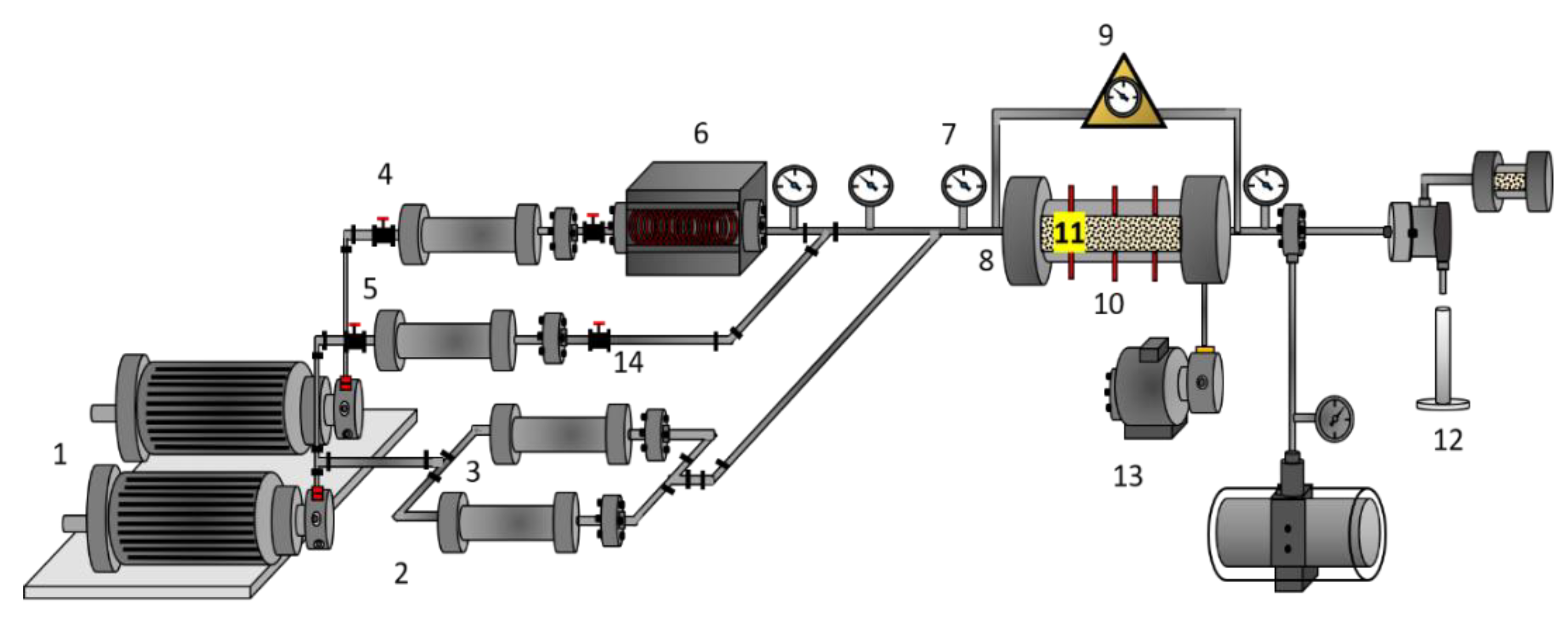
2.2.5. Steam Injection Tests in the Presence and Absence of Nanofluids

The evaluation of nanofluid at dynamic conditions was carried out in five stages including (i) basic characterization, (ii) oil recovery after steam injection in the absence of nanofluids, (iii) oil recovery after the injection of nanofluids for in situ upgrading, and (iv) N2 injection to obtain gas permeability baseline, and (v) oil recovery after the injection of the foaming nanofluid. The tests were conducted at a fixed back pressure of 110 psi, overburden pressure of 700 and 800 psi for basic characterization and steam injection tests, respectively and a temperature of 80 °C. For the basic characterization of the absolute and effective permeabilities, (Kabs and ko) are estimated applying Darcy’s law [55] by injecting water and oil at 0.5 mL3∙min−1 according to previous studies [59]. Then, the steam was injected into the porous medium between 3 and 5 mL·min−1 at 210 °C and 210 psi and a quality of 70% (X = 70%) and the oil recovery curves in the absence of the nanofluids were obtained. After, 0.5 pore volumes (PV) of the CeNi0.89Pd1.1 nanoparticles-based nanofluid for in situ upgrading were injected at 0.5 mL∙min−1 and left for a soaking time of 12 h. Then, steam was injected again to measure the oil recovery after the upgrading of the heavy crude oil. After that, 0.4 PV of the foaming nanofluid was injected at 3 mL∙min−1 to block preferential channels and allow the steam contact with the non-invaded area. The foam was generated in the porous medium trough the injection of 1.5 equivalent pore volumes equivalents (EPV) of N2 at a rate of 3 L∙min−1 to obtain a gas permeability baseline and verify, after divergent fluid injection, the foam in situ formation. The formation of the foam in situ is validated by the conductivity reduction of the system (Q∙Δ−1) and pressure changes. Finally, steam was injected to measure oil recovery after injection. In all cases the pressure drop was recorded, and the steam was injected until no more oil is produced.

2.2.6. Effluent Analysis

In order to evaluate the effect of the CeNi0.89Pd1.1 nanoparticles assisting steam injection processes, the changes of the EHO on its API gravity, viscosity, the content of saturates, aromatics, resins, and asphaltenes (SARA), and residue content (> 620 °C+) were estimated. The API gravity was measured using an Anton Paar Stabinger SVM 3000 rotating cylinder viscometer (Madrid, Spain). For the SARA analysis, micro de-asphalting was done to the extra-heavy oil and the upgraded oil using n-heptane and using the IP 469 method in an IATROSCAN MK6 TLC-FID/FPD equipment through hydrogen injection [36,60]. The viscosity measurements were made using a Kinexus Pro rheometer (Malvern Instruments, Worcestershire, UK). A parallel plate–plate geometry [61] (optimal for highly viscous fluids) was employed with a GAP of 0.3 mm, for different shear rates between 0 s−1 to 100 s−1 at 25 °C. The viscosity reduction degree (VRD) was calculated following the Equation (2) [61]:
VRD = ( μ v , EHO μ treat μ v , EHO ) 100
where μ v , EHO and μ treat are the viscosity of the virgin EHO and its viscosity after steam injection assisted by a nanofluid, respectively.
Finally, through high temperature simulated distillation (HTSD), the residue content was estimated following the American Society for Testing and Materials (ASTM) D-7169 standard in an Agilent 7890 chromatographer (Agilent Technologies, Wilmington, DE, USA) [62]. The residue content was calculated with Equation (3) [63]:
R % = ( R v , EHO R treat R v , EHO ) 100
where R v , EHO and R treat are the residue content of the virgin EHO and EHO after the steam and nanofluid injection, respectively.
Also, to describe the oil rheological behavior in the different stages of the oil recovery, the Cross model is proposed and showed in Table S1 of the Supplementary Material Document.

3. Results and Discussion

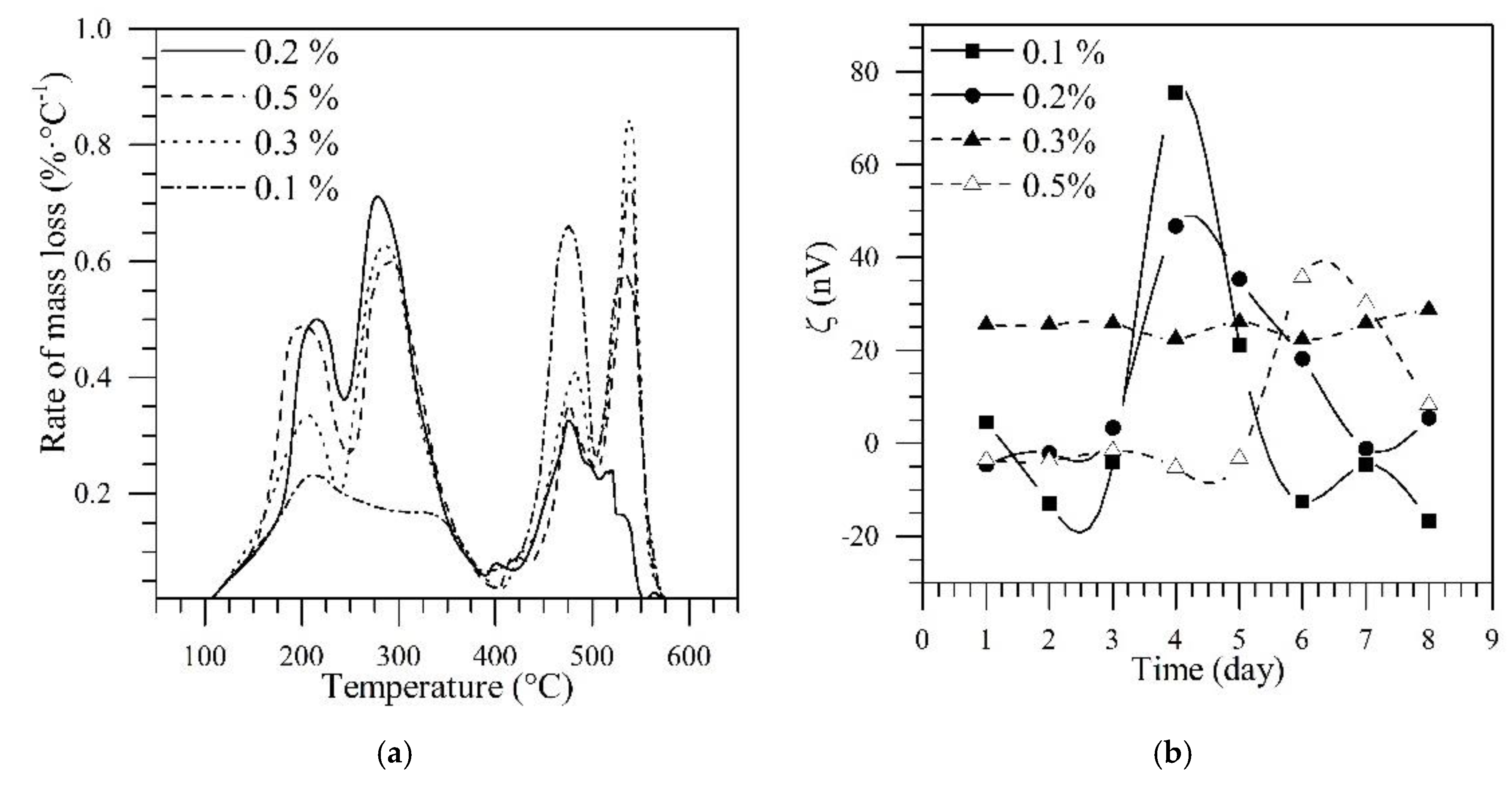
3.1. Selection of Nanocatalyst

The nanocatalyst selection was carried out through batch adsorption and thermogravimetric experiments. Initially, three bimetallic systems composed of the couples Ni-Pd, Fe-Pd, and Co-Pd, all supported over CeO2 nanoparticles, were subjected to an asphaltenes adsorption test. Subsequently, the decomposition of the adsorbed fractions was monitored through a gasification process under steam atmosphere [35]. The system with Ni-Pd nanocrystals, showed a greater adsorption capacity and a high affinity towards heavy hydrocarbons, over the other systems, favoured by Lewis acidity and effective nuclear charge that increases in the order Fe < Co < Ni [64]. In addition, this system has the ability to decompose the asphaltenes molecules at 220 °C, while the Co-Pd and Fe-Pd systems lead to decomposition temperatures around 230 and 240 °C, respectively. Further, a simplex-centroid mixture design was employed to optimize de asphaltenes conversion over the surface of Ni-Pd nanoparticles [35]. The statistical method showed that with a fraction mass of 0.89% and 1.1% of NiO and PdO, it is possible to convert 100% of the asphaltenes adsorbed in less than 80 min. A detailed description of these experiments is shown in previous studies [35,65].

3.2. Design of Nanofluid for in Situ Upgrading

Figure 2 shows the tests carried out for the formulation of the nanofluid to select the best concentration of CeNi0.89Pd1.1 nanoparticles and Tween 80 surfactant through (a) thermogravimetric and (b) zeta potential analysis, respectively. The nanoparticles and surfactant concentrations evaluated were 0.1%, 0.2%, 0.3%, and 0.5% in a mass fraction. From the panel (a) of Figure 2, it is possible to observe that the dosage of the treatment has a significant effect on the decomposition of the extra-heavy oil compounds, which is reflected in the intensities and temperature peaks for each sample. For the particular case of 0.1% of CeNi0.89Pd1.1 nanoparticles, the peaks around 470 °C and 540 are predominant, indicating that with this amount of nanoparticles, the decomposition temperature of the heaviest hydrocarbons occurs in this region and that a higher amount of nanoparticles is needed [65,66] as a consequence of the high content of heavy compounds in the crude oil. For concentrations of 0.2%, 0.3%, and 0.5% in a fraction mass of the nanoparticles, an increase the intensities of the peaks located around 210 and 280 °C is observed. This means that the catalytic effect of the nanoparticles starts to be significant regarding the amount of heavy compounds in the system from the dosage of 0.2%. At this concentration, the intensities of the peaks at low temperatures (<250 °C) is higher than for the other concentrations employed. Also, at high temperatures (>450 °C) the intensity of the peak for a concentration of 0.2% is the lowest in comparison with the other concentrations evaluated. These results could be due to concentrations higher than 0.2% lead to a higher nanoparticle aggregation and a reduction of the available surface area [57]. Hence, a nanoparticle dosage of 0.2% was selected for injection into the porous medium.
From Panel b in Figure 2 it can be observed that the surfactant concentration changes the nanofluid stability for a fixed concentration of CeNi0.89Pd1.1 nanoparticles of 0.2%. For surfactant concentrations ≤ 0.2%, the Z potential (ζ) of the system has fluctuations in both the stability zone (> 20 and < −20 mV) and the non-stability zone (−20–20 mV) [67]. On the other hand, the concentrations of 0.3% and 0.5% maintain the value constant of the ζ up to day 6 at 25 mV and −5 mV, respectively. The nanoparticles absorb surfactant and consequently, there are variations in the ζ. Probably for concentrations below 0.02%, the adsorption equilibrium is never reached, so the z potential is not stable. In this order, a dosage of 0.3% of Tween 80 surfactant was selected for nanofluid preparation. It is worth to mention here, according to previous studies, Tween 80 was selected as it has null influence on the heavy oil recovery and the main mechanisms are controlled by the nanoparticles [68]. The density and viscosity of the selected nanofluid were 1.12 cP and 0.998 g∙cm−3 at 25 °C.

3.3. Selection of the Foaming Nanofluid

Table 2 shows the values of the half-life time and durability of the foam generated with nanofluids of alpha-olefin sulfonate with a mass fraction of 0.5% and SPG12 nanoparticles. The nanoparticle concentration was varied between 0.01% and 1% in fraction mass. The best performance was obtained for the nanofluid with a concentration of 0.01% in a mass fraction of nanoparticles. The experimental results show that the addition of nanoparticles helps to double the half-life and triple the durability compared with the surfactant in the absence of the nanomaterial.
The measured density and viscosity of the nanofluid composed of the surfactant an 0.01% of SPG12 nanoparticles were 0.997 g∙cm−3 and 1.01 cP, respectively.

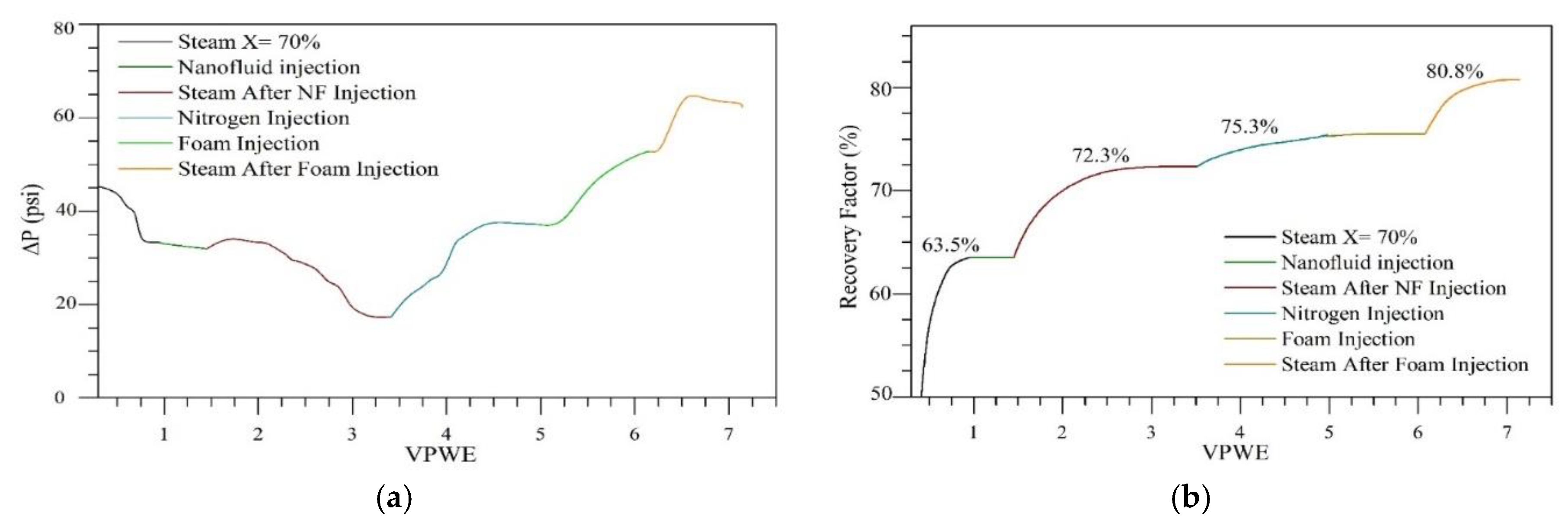
3.4. Displacement Tests

3.4.1. Steam Injection Process Assisted by Nanotechnology

The effect of the nanocatalyst and foaming nanofluid in the steam injection was developed in five main stages including, (i) basic characterization, (ii) steam injection in the absence of nanofluids, (iii) steam injection after soaking with nanofluid for in situ upgrading, (iv) N2 injection, and (v) steam injection after foaming nanofluid. The (a) oil recovery curves and (b) the system conductivity in each scenario are shown in Figure 3.
The absolute and oil effective permeability were estimated as 3627 and 2790 mD, respectively. After the first steam injection in the absence of nanoparticles, an oil recovery of 63.5% was obtained, and a pressure drop of 10 psi. In this case, the recovery is mainly due to the effect of oil viscosity reduction [69], thermal expansion [70], variation in capillary pressure, and relative permeability of the phases [36], volatilization of light hydrocarbons (C3–C5) [71], and gravitational segregation [72] caused by the transfer of steam energy to both fluids and to the porous medium. The steam injection without nanoparticles stopped after the injection of 1 equivalent pore volume of water (PVWE).
Then, in the case of the in situ upgrading, a dosage of 0.5 PV of CeNi0.89Pd1.1 nanoparticles-based nanofluid and a soak time of 12 h were employed. In this scenario, additional recovery of 8.8% is observed. The effect of the nanoparticles on the increase in the recovery obtained is mainly explained by for main mechanisms including: viscosity reduction, wettability alteration, enhanced thermal conductivity of the porous medium, and oil upgrading. First, the nanoparticles lead to the reduction in viscosity caused by a re-organization of the crude oil viscoelastic network [17,73,74]. This mechanism is explained considering that nanoparticle-asphaltene interactions are much stronger than asphaltene–asphaltene interactions [34,57,75,76], for this reason, asphaltene molecules are more prone to migrate from the bulk phase to the surface of the nanoparticles, generating a re-organization of the oil microstructure [74,77]. Consequently, the asphaltene aggregation system in the bulk phase will be affected as individual molecules and the smaller aggregates will be rapidly adsorbed by the CeNi0.89Pd1.1 nanoparticles [65]. On the other hand, the second mechanism associated with the enhanced oil recovery by the addition of nanoparticles is associated with the wettability alteration of the porous medium. It has been reported that nanoparticles allows the decoration of the porous media with CeNi0.89Pd1.1 nanoparticles which alter the system wettability to a strong water–wet, which favors the oil flow in the system [17].
The nanoparticles employed in this study also show high catalytic activity towards heavy fractions decomposition and improved thermal conductivity [78,79,80]. The asphaltene position in the active phases of the support and metal oxides promotes its conversion into lower molecular weight hydrocarbons [32,38,81,82], and gases such as CO [35], CO2 [35], and CH4, through the development of different reactions such as water–gas shift [83], methanation [84], steam reforming [38], partial oxidation [85], methane combustion, Boudouard, and hydrogenation [86,87]. Thanks to oxygen anions vacancies generated on the support during a redox cycle (Ce4+/Ce3+) [88] and the different interfaces NiO/CeO2±δ, PdO/CeO2±δ, NiO-PdO/CeO2±δ [65], nanoparticles are capable of increasing the interactions between the water vapor molecules (H2O(g)) adsorbed in oxygen vacancies [89] with the hydrocarbons, cracking and avoiding addition reactions [90,91]. It is important to emphasize that no injection of a hydrogen donor agent was made.
After, nitrogen injection was carried out in order to obtain the base gas permeability estimated as 771.9 mD. However, at this point, an increase in oil recovery from 72.3% to 75.3% was obtained. This incremental is associated with the steam condensation in the porous media, which worked as a divergent agent for the injected nitrogen, allowing the contact of areas that were not previously invaded by the steam. Finally, the injection of 1 PV of foaming nanofluid was made. The gas permeability at this point was established at 302.2 mD, decreasing approximately 60%. The in situ formation of the foam was carried out successfully and is corroborated by the change in conductivity from 71.15 to 26 cm3·min−1·psi−1 for the base system and after the foam injection, respectively. Again, continuous steam injection was made, obtaining an additional recovery of 6.5%.
In the case of the pressure profile in panel b from Figure 3, initially the pressure drops due to the oil displacement by the steam injected into the porous medium. Then, the injection of the nanofluid does not generate a significant change in the system pressure. Besides, the steam injection after nanofluid injection, promotes an additional sudden drop in pressure due to the improvement in oil quality with less restriction to flow.
For nitrogen injection, an increase in pressure is observed because the condensed liquids could cause a divergent effect. When the pressure values stabilize, the foaming agent is injected, and the pressure increases which corroborates the improved foam formation. Finally, during steam injection, a pressure incremental is maintained and then, decreases due to crude oil displacement from the non-invaded area.
Finally, Table 3 shows the oil and water saturation states in each stage, as well as the ultimate oil recovery and incremental recovery. Here it is important to clarify that saturation states were determined regarding the system prior to the first oil recovery by steam injection in order not to overestimate the volumes recovered and the oil recovery factor.

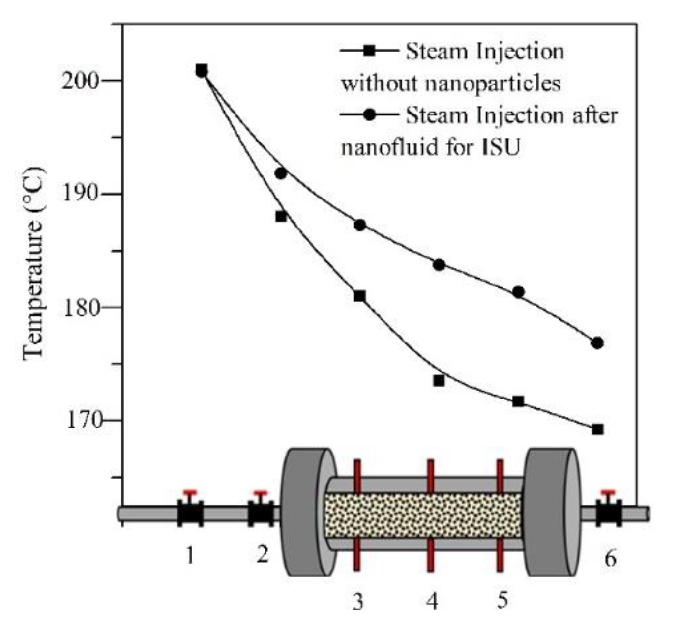
3.4.2. Temperature Profile during Steam Injection Tests

The temperature profile through 6 nodes located at the beginning, inside, and at the exit of the porous media, for the steam injection scenarios with and without nanocatalysts is shown in Figure 4. The temperature in each of the nodes was measured using integrated thermocouples along the steam generator output line and the entire sample-holder in order to corroborate the improved thermal conductivity. The drop-in temperature in general is due primarily to the tortuosity of the medium [92,93], to the energy transfer from the steam to the fluids (water and oil) [94], and the composition of the rock (99% silica) can be considered as heat sinks [95]. On the other hand, the change in temperature for the system after the nanofluid injection was lower than in the absence thereof. In the absence of nanocatalyst the temperature drops 127 °C, while after nanofluid injection it is 95.5 °C. Besides, in each node, the temperature tested is always lower for the first scenario compared with the second. The chemical structure that nanoparticles acquire with the metal impregnation improves the conductivity of porous media and hence the heat of transfer is higher than without nanoparticles. Also, the system due to nanoscale metal oxides allows the adsorption of heat very quickly, improving the heat capacity of the injected steam when the molecules interact within the porous medium [96,97,98].

3.5. Crude Oil Characterization

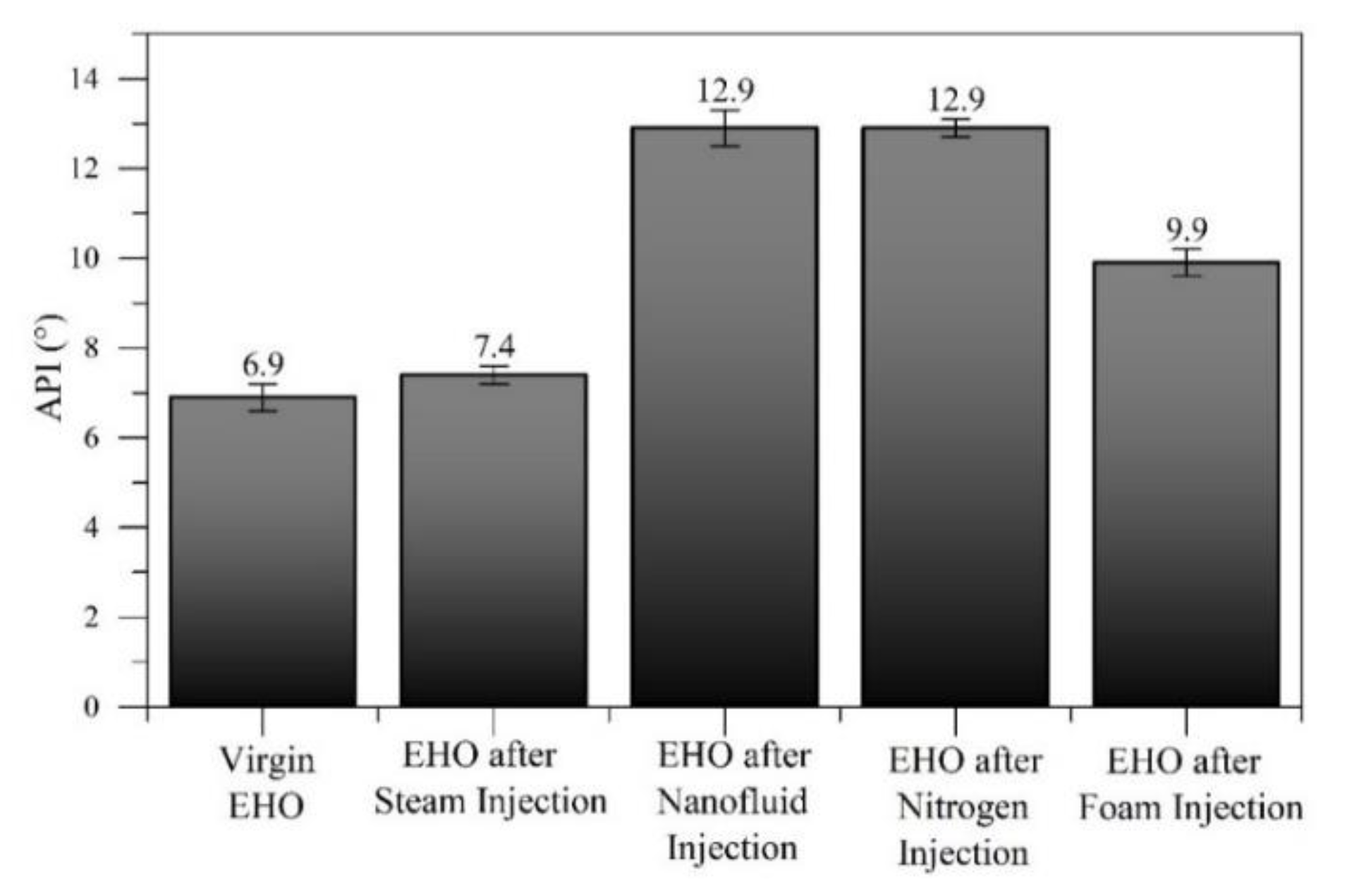
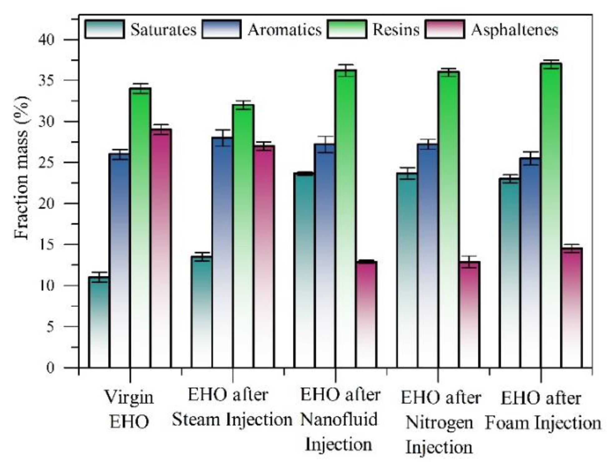
3.5.1. API Gravity, Residue Conversion (R%) and SARA Content

The crude oil upgrading is estimated based on changes in API gravity values. Figure 5 shows the values obtained from the calculation of the API gravity for the oil produced after the steam injection, without nanoparticles, steam injection after soaking with nanofluid for in situ upgrading, N2 injection, and steam injection after foaming nanofluid. The API increases by 6.7%, 46.5%, 50%, and 51.7% for each stage, respectively The change in API gravity is related to the decomposition of the asphaltenes molecules adsorbed on the nanoparticles’ surface that leads to the formation of components of lower molecular weight by the development of gasification reactions between H2O(g) molecules, heavy hydrocarbons, and functional groups on the surface of the NPs [35,65,66,99]. The presence of only steam achieves a slight change in API gravity possibly because at that temperature, there may be a rearrangement of the molecules within the fluid achieving a small change in the fraction of the heavy oil fractions [100]. Meanwhile, the nanofluid injection promotes the catalytic oil upgrading and the hydrogen production generated from water and water–gas shift reaction [101]. Hence, free alkyl chain molecules convert into lighter molecules, and the hydrogenation of the cracked radicals is performed to avoid addition reactions [102].
The similarity in the API gravity values obtained for the effluents collected during nitrogen injection and after foam formation with the steam injection assisted by CeNi0.89Pd1.1 nanocatalysts is possibly related to retention phenomena and gravitational segregation of nanoparticles, caused by steam condensation. In this order, nanoparticles achieved contact with non-invaded zones and generated an upgrading in crude oil quality that later was mobilized by nitrogen current, and steam current after the foam formation. These results agree with the reported by our research group [17] and Hamedi et al. [103,104].
On the other hand, Figure 6 shows the percentage in the mass fraction of saturates, aromatics, resins, and asphaltenes content of the effluents obtained in each stage. For the injection of steam without nanoparticles, no appreciable or significant change in the asphaltene content is observed. It is due to the thermal decomposition of these compounds occurring at much higher temperatures, around 450 °C [34,35,66]. The presence of CeNi0.89Pd1.1 nanoparticles generates a decrease from 28.7% to 12.9%, 12.9%, and 14.5% of the asphaltenes content in the system for the respective stage after the injection of nanofluid for in situ upgrading, nitrogen injection, and divergent agent injection, respectively, demonstrating the high catalytic activity of the catalyst. Thanks to the beneficial effect between the metal oxides on the surface of the nanoparticles [83], the development of the redox cycle by the support [65], the anions oxygen vacancies provided by Ce3+ ions for the adsorption of water vapor molecules [105], and the catalysis of reactions that favor hydrogen production [106], a great improvement in the quality of the heavy crude oil is obtained, reducing the presence of heavy oil compounds, increasing the saturated components, and reducing in turn the presence of aromatic content.
Finally, the residue conversion (%R) follows the order: oil after ISU ≈ oil after N2 injection > oil after foam injection > oil after steam injection in the absence of nanoparticles. In each system, the obtained %R was 30.5 ± 0.2, 30.3 ± 0.2, 14.3 ± 0.2, and 3.6 ± 0.4, respectively. These results corroborate the formation of hydrocarbons of lower molecular weight and the suppression of the addition reactions, in agreement with the increase in the content of saturated components, and the decrease of the asphaltenes compounds.

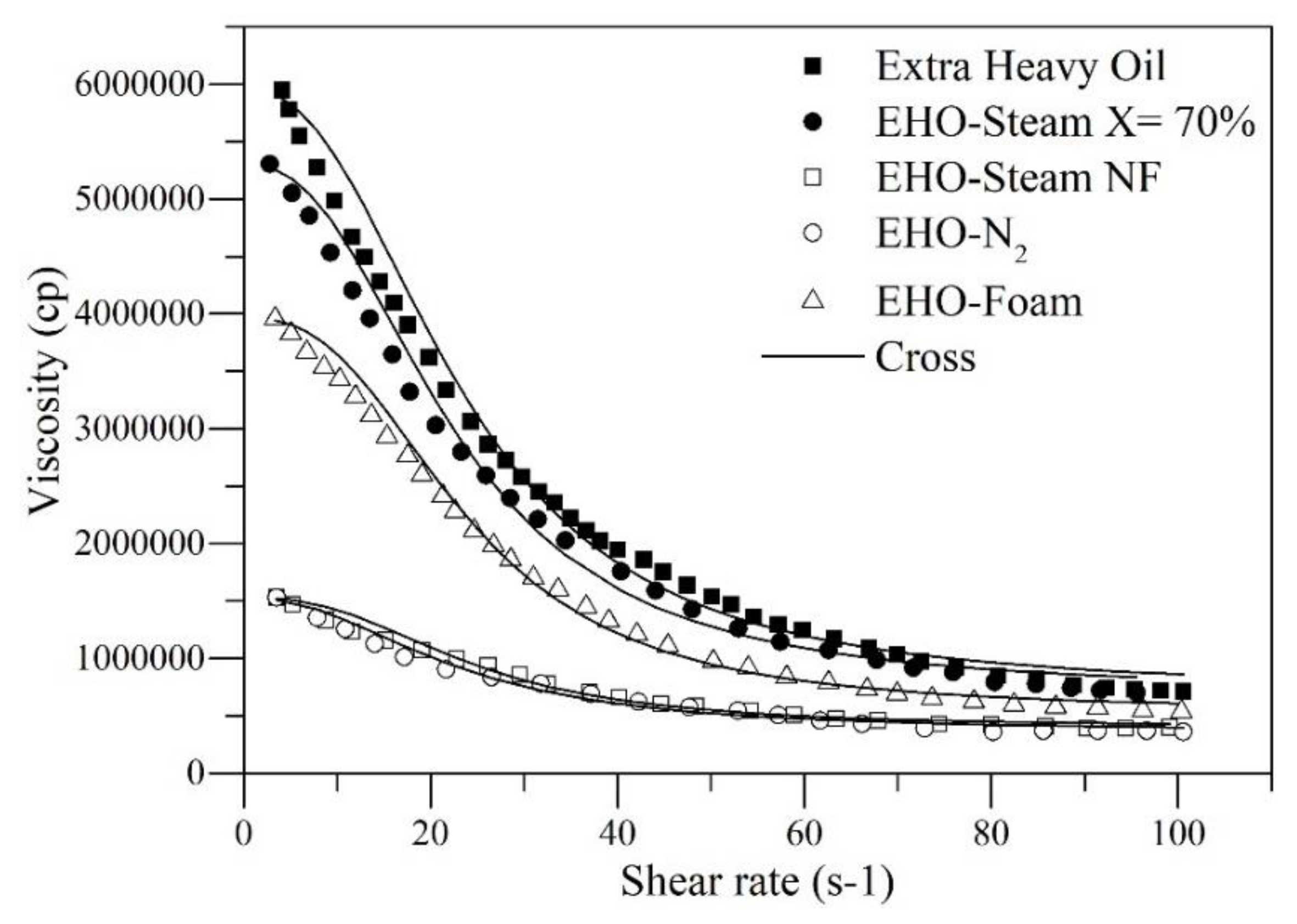
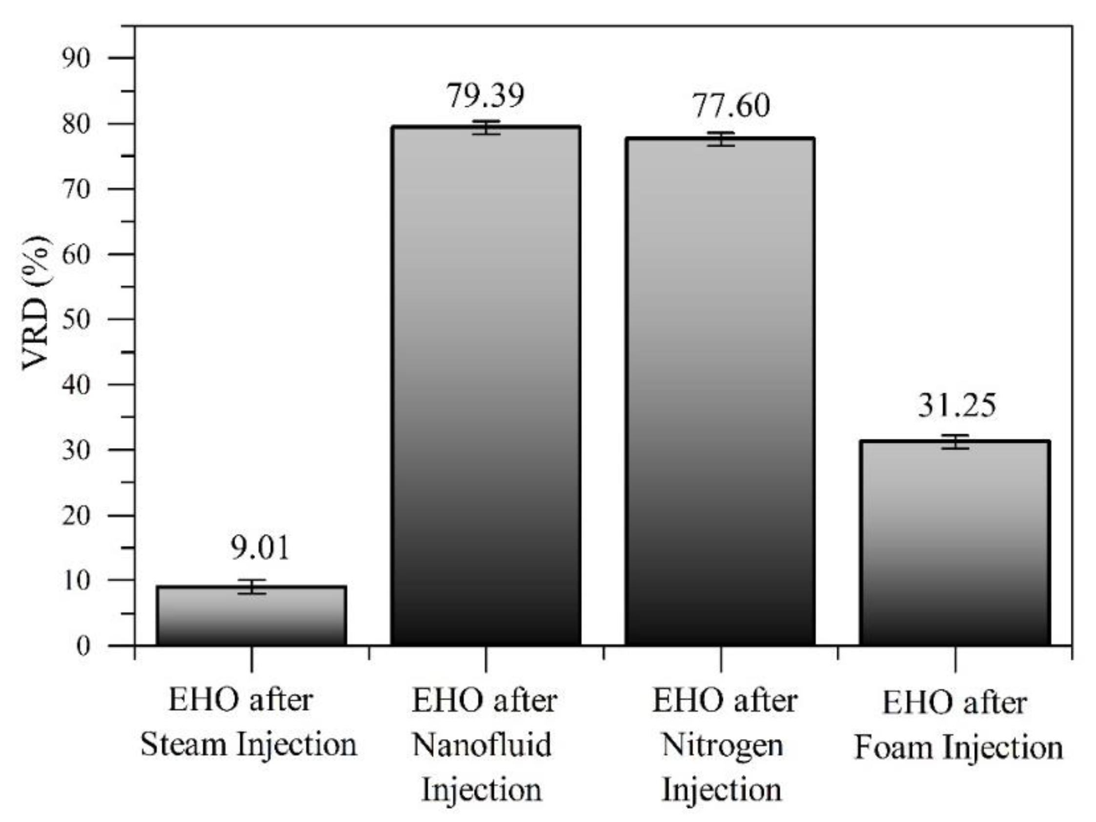
3.5.2. Rheological Behavior

The rheological behavior of the oil obtained after the different steps of the displacement tests is showed in Figure 7, where it is observed that to the extent that heat enters the porous media at residual oil conditions, the viscosity values fall exponentially with the increase in shear rate, indicating the pseudoplastic nature of the virgin extra-heavy oil before and after steam injection [107]. However, an initial decrease in viscosity values is observed after the injection of steam because the viscous forces are surpassed by the kinetic energy of the system [108]. On the other hand, the presence of CeNi0.89Pd1.1 nanocatalysts generates a considerable reduction in viscosity related to the viscoelastic network disruption, besides the asphaltenes aggregates sizes, are reduced, making the asphaltene-asphaltene interactions limited by the increase in nanoparticle-asphaltene interactions [109,110]. This behavior is similar to the reported by Cardona et al. [36] and Shokrlu et al. [111].
The typical oil behavior is non-Newtonian, where the viscosity changes with the shear rate and becomes more noticeable at the lower values; notwithstanding, the nanocatalyst injection modifies the rheological properties making that the EHO behaves more as a Newtonian fluid and reducing its viscosity in all the shear rate range [61]. In this sense, the effluent obtained after the CeNi0.89Pd1.1 base-nanofluid injection, presents the best performance in terms of viscosity reduction, and rheological behavior; due to when the shear rate increases, the behavior of the fluid analyzed begins to be like a Newtonian liquid, since the internal structure of the fluid does not change drastically, independently of the shear rate. Thus, independently of the shear rate, the internal structure of the fluid recovered after the CeNi0.89Pd1.1 base-nanofluid injection does not change drastically. Finally, Cross model parameters are shown in Table S2 of the Supplementary Material Document, along with the %RMSE values.
With the values from Table S2, it is observed that for all fluids there is a RMSE% < 1%, which means that the model adjusts to the rheological behavior exhibited by the crude oil studied in the different stages. For the extreme viscosity parameters at zero and infinity, the values decrease in the order virgin EHO < steam injection < foam injection < nitrogen injection < steam injection assisted by CeNi0.89Pd1.1 base-nanofluid, corroborating the change in properties of the fluid through its stimulation in steam injection and nanotechnology application.
Figure 8 shows the percentage of viscosity reduction (%VRD) for a shear rate value of 10 s−1, such that the change for each of the recovered fluids is compared to untreated extra-heavy oil.
This is the first measurement, the steam injection generates a %VRD of approximately 7.2%, due to the latent heat transferred by the steam towards the formation fluids, increasing the crude oil mobility, without generating a significant increase in the quality of the same. On the other hand, the catalytic effect of the nanoparticles, their capacity to mediate water–gas shift reactions for the hydrogen production taking advantage of the formation of CO [103], and considering the lower activation energy required to break the C–S bond [112], added to the high electronegativity of S and that the H+ ions attack mainly sulfur atoms, with the effect of high pressure and temperature, reactions of aquathermolysis are developed [71], breaking C–S and C = S bonds, interrupting the crude oil viscoelastic network and considerably decreasing crude oil viscosity by approximately 79.39%, 77.60%, and 31.25%, for the three scenarios evaluated, respectively.
Considering the previous results, among the advantages offering by the use of CeNi0.89Pd1.1 nanocatalysts to assist the steam injection processes are: (1) reduction of heat consumption, the catalyst in contact with oil molecules accelerate the cracking and decomposition of heavy hydrocarbons, promoting more heat and gaseous products that further improve the oil displacement; (2) reduction of water consuming, because with its application, it is possible to achieve the same recovery values with much less steam injected. This behavior is consistent with several reported studies [17], even leading to a decrease in the water cut [113]; and (3) reduction of toxic chemicals and capital costs of lifting and transportation operations. The main techniques that exist for the OH and EHO transportation require the addition of solvents (light crude oil, naphtha, diesel, among others) or gasses (mainly, CO2), as they contribute to reducing oil viscosity [114,115,116,117]. High consumption of solvents increases transportation costs and generates different environmental risks due to the production of polluting gasses. It has been shown that with the addition of 0.2% by mass of CeNi0.89Pd1.1 nanocatalyst, a reduction of approximately 80% of viscosity is achieved. Finally, (4) Reduction of greenhouse gases, CO2 leakage prevention mechanism through nanoparticle application have been reported. All advantages mentioned make evident that nanoparticles applied in EOR processes have the ability to improve oil production being environmentally friendly, less expensive, and more efficient compared to traditional treatments [118].

4. Conclusions

Thanks to the catalytic advantages that CeO2-based materials present, the nanocatalyst employed in this study showed a high performance in terms of oil recovery factor and quality improvement of extra-heavy oil. In this way, comparing the scenario in the absence of these nanomaterials, there is a significant increase in all the properties of crude oil. Starting with an increase in oil recoverable, followed by improvement in properties such as a decrease in asphaltene content, increase in API values, and viscosity reduction. Increases in oil recovery from 63.5% to 72.3%, 75.3%, and 80.8% are obtained for the injection of nanofluid, nitrogen, and foaming agent. Besides the quality of the EHO was improved, reducing its asphaltene content in 15.8%, 15.8%, and 14.2% unites for the same respective stages. Finally, the implementation of CeNi0.89Pd1.1 nanocatalysts shows improvements of the steam injection processes, to the extent that it was not necessary to use a hydrogen donor agent to promote its high performance.

Supplementary Materials

The following are available online at https://0-www-mdpi-com.brum.beds.ac.uk/1996-1073/12/24/4633/s1, Figure S1. Schematic representation of the experimental setup to perform stability tests of foams. Experimental conditions: Flow rate = 0.4 L∙min−1; Temperature = 90 °C. Components: 1. hot water bath; 2. peristaltic pump; 3. universal support; 4. graduated concentric cylinder with porous disk at the bottom; 5. check valve; 6. flow regulator; 7. nitrogen tank. Table S1. Rheological models Cross and their respective parameters. Table S2. Cross model parameter for virgin extra-heavy oil and oil recovered with steam injection 70% quality assisted by CeNi0.89Pd1.1 nanoparticles and divergent agent.

Author Contributions

Conceptualization, O.E.M., F.B.C. and C.A.F.; methodology, O.E.M., C.C.-V., Y.H., M.R., S.H.L., and C.A.F.; formal analysis, O.E.M., C.A.F. and S.H.L.; investigation, O.E.M., Y.H., C.A.F.; writing—original draft preparation, O.E.M. and Y.H.; writing—review and editing, all authors.

Funding

The authors would like to acknowledge to Fondo Nacional De Financiamiento Para La Ciencia, La Tecnología y La Innovación “Francisco José De Caldas”, Agencia Nacional De Hidrocarburos and Colciencias for their support provided in Agreement 272 of 2017. We would also like to recognize the Universidad Nacional de Colombia for logistical and financial support.

Acknowledgments

The authors also acknowledge Grupo de Investigación en Fenómenos de Superficie–Michael Polanyi.

Conflicts of Interest

The authors declare no conflict of interest.

References

  1. Calemma, V.; Iwanski, P.; Nali, M.; Scotti, R.; Montanari, L. Structural characterization of asphaltenes of different origins. Energy Fuels 1995, 9, 225–230. [Google Scholar] [CrossRef]
  2. Boduszynski, M.M. Composition of heavy petroleums. 2. Molecular characterization. Energy Fuels 1988, 2, 597–613. [Google Scholar] [CrossRef]
  3. Medina, O.E.; Gallego, J.; Rodriguez, E.; Franco, C.A.; Cortés, F.B. Effect of Pressure on the Oxidation Kinetics of Asphaltenes. Energy Fuels 2019, 33, 10734–10744. [Google Scholar] [CrossRef]
  4. Tremblay, B.; Sedgwick, G.; Forshner, K. Simulation of cold production in heavy-oil reservoirs: Wormhole dynamics. SPE Reserv. Eng. 1997, 12, 110–117. [Google Scholar] [CrossRef]
  5. Langevin, D.; Poteau, S.; Hénaut, I.; Argillier, J. Crude oil emulsion properties and their application to heavy oil transportation. Oil Gas Sci. Technol. 2004, 59, 511–521. [Google Scholar] [CrossRef]
  6. Banerjee, D.K. Oil Sands, Heavy Oil & Bitumen: From Recovery to Refinery; PennWell Books: Tulsa, OK, USA, 2012. [Google Scholar]
  7. Acevedo, S.; Zuloaga, C.; Rodríguez, P. Aggregation—Dissociation studies of asphaltene solutions in resins performed using the combined freeze fracture—Transmission electron microscopy technique. Energy Fuels 2008, 22, 2332–2340. [Google Scholar] [CrossRef]
  8. Acevedo, S.; Méndez, B.; Rojas, A.; Layrisse, I.; Rivas, H. Asphaltenes and resins from the Orinoco basin. Fuel 1985, 64, 1741–1747. [Google Scholar] [CrossRef]
  9. Ancheyta, J.; Centeno, G.; Trejo, F.; Marroquin, G.; Garcia, J.; Tenorio, E.; Torres, A. Extraction and characterization of asphaltenes from different crude oils and solvents. Energy Fuels 2002, 16, 1121–1127. [Google Scholar] [CrossRef]
  10. Andersen, S.I.; Speight, J.G. Petroleum resins: Separation, character, and role in petroleum. Pet. Sci. Technol. 2001, 19, 1–34. [Google Scholar] [CrossRef]
  11. Bera, A.; Babadagli, T. Status of electromagnetic heating for enhanced heavy oil/bitumen recovery and future prospects: A review. Appl. Energy 2015, 151, 206–226. [Google Scholar] [CrossRef]
  12. Shah, A.; Fishwick, R.; Wood, J.; Leeke, G.; Rigby, S.; Greaves, M. A review of novel techniques for heavy oil and bitumen extraction and upgrading. Energy Environ. Sci. 2010, 3, 700–714. [Google Scholar] [CrossRef]
  13. McKay, A.S.; Nasr, T.N. Recovery of Bitumen or Heavy Oil in Situ by Injection of Hot Water of Low Quality Steam Plus Caustic and Carbon Dioxide. U.S. Patent No. 5,056,596, 15 October 1991. [Google Scholar]
  14. Jorshari, K.; O’Hara, B. A new SAGD-well-pair placement: A field case review. J. Can. Pet. Technol. 2013, 52, 12–19. [Google Scholar] [CrossRef]
  15. Kar, T.; Ovalles, C.; Rogel, E.; Vien, J.; Hascakir, B. The residual oil saturation determination for Steam Assisted Gravity Drainage (SAGD) and Solvent-SAGD. Fuel 2016, 172, 187–195. [Google Scholar] [CrossRef]
  16. Liu, H.; Cheng, L.; Huang, S.; Jia, P.; Chen, M. Evolution characteristics of SAGD steam chamber and its impacts on heavy oil production and heat consumption. Int. J. Heat Mass Transf. 2018, 121, 579–596. [Google Scholar] [CrossRef]
  17. Franco, C.; Cardona, L.; Lopera, S.; Mejía, J.; Cortés, F. Heavy oil upgrading and enhanced recovery in a continuous steam injection process assisted by nanoparticulated catalysts. In Proceedings of the SPE Improved Oil Recovery Conference, Tulsa, OK, USA, 11–13 April 2016. [Google Scholar]
  18. Luft, H.; Pelensky, P.; George, G. Development and operation of a new insulated concentric coiled tubing string for continuous steam injection in heavy oil production. In Proceedings of the SPE International Heavy Oil Symposium, Calgary, AB, Canada, 19–21 June 1995. [Google Scholar]
  19. Melcon, S. Oil Recovery by in Situ Combustion. U.S. Patent No. 3,165,154, 12 January 1965. [Google Scholar]
  20. Dabbous, M.K.; Fulton, P.F. Low-temperature-oxidation reaction kinetics and effects on the in-situ combustion process. Soc. Pet. Eng. J. 1974, 14, 253–262. [Google Scholar] [CrossRef]
  21. Jiang, S.; Liu, X.; Liu, Y.; Zhong, L. In situ upgrading heavy oil by aquathermolytic treatment under steam injection conditions. In Proceedings of the SPE International Symposium on Oilfield Chemistry, The Woodlands, TX, USA, 2–4 February 2005. [Google Scholar]
  22. Kapadia, P.R.; Kallos, M.S.; Gates, I.D. A review of pyrolysis, aquathermolysis, and oxidation of Athabasca bitumen. Fuel Process. Technol. 2015, 131, 270–289. [Google Scholar] [CrossRef]
  23. Ali, S. Current status of steam injection as a heavy oil recovery method. J. Can. Pet. Technol. 1974, 13, 54–68. [Google Scholar] [CrossRef]
  24. Sandiford, B.B. Gel and Method for Reducing Steam Channeling. U.S. Patent No. 4,665,986, 19 May 1987. [Google Scholar]
  25. Aljundi, I.H. Energy and exergy analysis of a steam power plant in Jordan. Appl. Therm. Eng. 2009, 29, 324–328. [Google Scholar] [CrossRef]
  26. Herranz, L.E.; Anderson, M.H.; Corradini, M.L. A diffusion layer model for steam condensation within the AP600 containment. Nucl. Eng. Des. 1998, 183, 133–150. [Google Scholar] [CrossRef]
  27. Nassar, N.N.; Hassan, A.; Pereira-Almao, P. Application of nanotechnology for heavy oil upgrading: Catalytic steam gasification/cracking of asphaltenes. Energy Fuels 2011, 25, 1566–1570. [Google Scholar] [CrossRef]
  28. Choi, S.U.; Eastman, J.A. Enhancing Thermal Conductivity of Fluids with Nanoparticles; Argonne National Lab.: Lemont, IL, USA, 1995. [Google Scholar]
  29. Li, W.; Ni, C.; Lin, H.; Huang, C.; Shah, S.I. Size dependence of thermal stability of TiO2 nanoparticles. J. Appl. Phys. 2004, 96, 6663–6668. [Google Scholar] [CrossRef] [Green Version]
  30. Hwang, Y.-j.; Lee, J.; Lee, C.; Jung, Y.; Cheong, S.; Lee, C.; Ku, B.; Jang, S. Stability and thermal conductivity characteristics of nanofluids. Thermochim. Acta 2007, 455, 70–74. [Google Scholar] [CrossRef]
  31. Adams, J.J. Asphaltene adsorption, a literature review. Energy Fuels 2014, 28, 2831–2856. [Google Scholar] [CrossRef]
  32. Franco, C.A.; Montoya, T.; Nassar, N.N.; Cortés, F.B. NiO and PdO Supported on Fumed Silica Nanoparticles for Adsorption and Catalytic Steam Gasification of Colombian n-C7 Asphaltenes. Handb. Oil Prod. Res. 2014, 26, 101–145. [Google Scholar]
  33. Cardona Rojas, L. Efecto de Nanopartículas en Procesos con Inyección de Vapor a Diferentes Calidades. Master’s Thesis, Universidad Nacional de Colombia-Sede Medellín, Antioquia, Colombia, March 2018. [Google Scholar]
  34. Nassar, N.N.; Franco, C.A.; Montoya, T.; Cortés, F.B.; Hassan, A. Effect of oxide support on Ni–Pd bimetallic nanocatalysts for steam gasification of n-C7 asphaltenes. Fuel 2015, 156, 110–120. [Google Scholar] [CrossRef]
  35. Medina, O.E.; Gallego, J.; Arias-Madrid, D.; Cortés, F.B.; Franco, C.A. Optimization of the Load of Transition Metal Oxides (Fe2O3, Co3O4, NiO and/or PdO) onto CeO2 Nanoparticles in Catalytic Steam Decomposition of n-C7 Asphaltenes at Low Temperatures. Nanomaterials 2019, 9, 401. [Google Scholar] [CrossRef] [Green Version]
  36. Cardona, L.; Arias-Madrid, D.; Cortés, F.; Lopera, S.; Franco, C. Heavy oil upgrading and enhanced recovery in a steam injection process assisted by NiO-and PdO-Functionalized SiO2 nanoparticulated catalysts. Catalysts 2018, 8, 132. [Google Scholar] [CrossRef] [Green Version]
  37. Badoga, S.; Sharma, R.V.; Dalai, A.K.; Adjaye, J. Hydrotreating of Heavy Gas Oil on Mesoporous Mixed Metal Oxides (M–Al2O3, M = TiO2, ZrO2, SnO2) Supported NiMo Catalysts: Influence of Surface Acidity. Ind. Eng. Chem. Res. 2014, 53, 18729–18739. [Google Scholar] [CrossRef]
  38. Gao, Y.; Ghorbanian, B.; Gargari, H.N.; Gao, W. Steam reforming of gaseous by-products from bitumen oil using various supported Ni-based catalysts. Pet. Sci. Technol. 2018, 36, 34–39. [Google Scholar] [CrossRef]
  39. Guo, K.; Zhang, Y.; Shi, Q.; Yu, Z. The effect of carbon-supported nickel nanoparticles in the reduction of carboxylic acids for in situ upgrading of heavy crude oil. Energy Fuels 2017, 31, 6045–6055. [Google Scholar] [CrossRef]
  40. Vignatti, C.I.; Avila, M.S.; Apesteguia, C.R.; Garetto, T.F. Study of the water-gas shift reaction over Pt supported on CeO2–ZrO2 mixed oxides. Catal. Today 2011, 171, 297–303. [Google Scholar] [CrossRef]
  41. Yi, S.; Babadagli, T.; Li, H.A. Use of nickel nanoparticles for promoting aquathermolysis reaction during cyclic steam stimulation. SPE J. 2018, 23, 145–156. [Google Scholar] [CrossRef]
  42. Afzal, S.; Nikookar, M.; Ehsani, M.R.; Roayaei, E. An experimental investigation of the catalytic effect of Fe2O3 nanoparticle on steam injection process of an Iranian reservoir. Iran. J. Oil Gas Sci. Technol. 2014, 3, 27–36. [Google Scholar]
  43. Rossen, W.R. Foams in enhanced oil recovery. Foam. Theory Meas. Appl. 1996, 57, 413–464. [Google Scholar]
  44. Hiraski, G.J. The steam-foam process. J. Pet. Technol. 1989, 41, 449–456. [Google Scholar] [CrossRef]
  45. Dilgren, R.E.; Owens, K.B. Steam-foaming surfactant mixtures which are tolerant of divalent ions. U.S. Patent No. 4,643,256, 17 February 1987. [Google Scholar]
  46. Sanders, A.; Dado, G.P.; Holland, B.; Dong, X.M.; Rojas, C.E. Steam Foam Methods for Steam-Assisted Gravity Drainage. U.S. Patent Application No. 15/503,293, 10 August 2017. [Google Scholar]
  47. Sun, Q.; Li, Z.; Wang, J.; Li, S.; Li, B.; Jiang, L.; Wang, H.; Lü, Q.; Zhang, C.; Liu, W. Aqueous foam stabilized by partially hydrophobic nanoparticles in the presence of surfactant. Colloids Surf. A Physicochem. Eng. Asp. 2015, 471, 54–64. [Google Scholar] [CrossRef]
  48. Pang, Z.; Liu, H.; Zhu, L. A laboratory study of enhancing heavy oil recovery with steam flooding by adding nitrogen foams. J. Pet. Sci. Eng. 2015, 128, 184–193. [Google Scholar] [CrossRef]
  49. Singh, R.; Mohanty, K.K. Synergistic stabilization of foams by a mixture of nanoparticles and surfactants. In Proceedings of the SPE Improved Oil Recovery Symposium, Tulsa, OK, USA, 12–16 April 2014. [Google Scholar]
  50. Nguyen, P.; Fadaei, H.; Sinton, D. Pore-scale assessment of nanoparticle-stabilized CO2 foam for enhanced oil recovery. Energy Fuels 2014, 28, 6221–6227. [Google Scholar] [CrossRef]
  51. Hurtado, Y.; Beltrán, C.; Zabala, R.D.; Lopera, S.H.; Franco, C.A.; Nassar, N.N.; Cortés, F.B. Effects of Surface Acidity and Polarity of SiO2 Nanoparticles on the Foam Stabilization Applied to Natural Gas Flooding in Tight Gas-Condensate Reservoirs. Energy Fuels 2018, 32, 5824–5833. [Google Scholar] [CrossRef]
  52. Hurtado, Y.; Franco, C.A.; Cortés, F.B. Mejoramiento de espumas de Nitrogéno por adición de nanopartículas parcialmente hidrofobicas. In Proceedings of the SPETC, Medellín, Colombia, 28 May 2018. [Google Scholar]
  53. Ostgard, D.; Kustov, L.; Poeppelmeier, K.R.; Sachtler, W. Comparison of Pt/KL catalysts prepared by ion exchange or incipient wetness impregnation. J. Catal. 1992, 133, 342–357. [Google Scholar] [CrossRef]
  54. Ramakrishnan, T.; Cappiello, A. A new technique to measure static and dynamic properties of a partially saturated porous medium. Chem. Eng. Sci. 1991, 46, 1157–1163. [Google Scholar] [CrossRef]
  55. Whitaker, S. Flow in porous media I: A theoretical derivation of Darcy’s law. Transp. Porous Media 1986, 1, 3–25. [Google Scholar] [CrossRef]
  56. Scheffe, H. The simplex-centroid design for experiments with mixtures. J. R. Stat. Soc. Ser. B 1963, 25, 235–251. [Google Scholar] [CrossRef]
  57. Guzmán, J.D.; Betancur, S.; Carrasco-Marín, F.; Franco, C.A.; Nassar, N.N.; Cortés, F.B. Importance of the adsorption method used for obtaining the nanoparticle dosage for asphaltene-related treatments. Energy Fuels 2016, 30, 2052–2059. [Google Scholar] [CrossRef]
  58. Mukherjee, S.; Paria, S. Preparation and stability of nanofluids—A Review. IOSR J. Mech. Civ. Eng. 2013, 9, 63–69. [Google Scholar] [CrossRef]
  59. Giraldo, J.; Benjumea, P.; Lopera, S.; Cortés, F.B.; Ruiz, M.A. Wettability alteration of sandstone cores by alumina-based nanofluids. Energy Fuels 2013, 27, 3659–3665. [Google Scholar] [CrossRef]
  60. Bansal, V.; Krishna, G.; Chopra, A.; Sarpal, A. Detailed hydrocarbon characterization of RFCC feed stocks by NMR spectroscopic techniques. Energy Fuels 2007, 21, 1024–1029. [Google Scholar] [CrossRef]
  61. Montes, D.; Orozco, W.; Taborda, E.A.; Franco, C.A.; Cortés, F.B. Development of Nanofluids for Perdurability in Viscosity Reduction of Extra-Heavy Oils. Energies 2019, 12, 1068. [Google Scholar] [CrossRef] [Green Version]
  62. Austrich, A.; Buenrostro-Gonzalez, E.; Lira-Galeana, C. ASTM D-5307 and ASTM D-7169 SIMDIS standards: A comparison and correlation of methods. Pet. Sci. Technol. 2015, 33, 657–663. [Google Scholar] [CrossRef]
  63. Hashemi, R.; Nassar, N.N.; Pereira-Almao, P. Transport behavior of multimetallic ultradispersed nanoparticles in an oil-sands-packed bed column at a high temperature and pressure. Energy Fuels 2012, 26, 1645–1655. [Google Scholar] [CrossRef]
  64. Brewer, L.; Wengert, P.R. Erratum to: Transition metal alloys of extraordinary stability; An example of generalized Lewis-acid-base interactions in metallic systems. Metall. Trans. 1973, 4, 83–104. [Google Scholar] [CrossRef]
  65. Medina, O.E.; Gallego, J.; Restrepo, L.G.; Cortés, F.B.; Franco, C.A. Influence of the Ce4+/Ce3+ Redox-Couple on the Cyclic Regeneration for Adsorptive and Catalytic Performance of NiO-PdO/CeO2±δ Nanoparticles for n-C7 Asphaltene Steam Gasification. Nanomaterials 2019, 9, 734. [Google Scholar] [CrossRef] [Green Version]
  66. Franco, C.A.; Nassar, N.N.; Montoya, T.; Ruíz, M.A.; Cortés, F.B. Influence of asphaltene aggregation on the adsorption and catalytic behavior of nanoparticles. Energy Fuels 2015, 29, 1610–1621. [Google Scholar] [CrossRef]
  67. Clogston, J.D.; Patri, A.K. Zeta potential measurement. In Characterization of Nanoparticles Intended for Drug Delivery; Springer: Berlin, Germany, 2011; pp. 63–70. [Google Scholar]
  68. Franco, C.A. Synthesis and Application of Supported Metallic and Multi-Metallic Oxides Nanoparticles for In-Situ Upgrading and Inhibition of Formation Damage; Universidad Nacional de Colombia-Sede Medellín: Antioquia, Colombia, 2015. [Google Scholar]
  69. Li, X.; Shi, L.; Li, H.; Liu, P.; Luo, J.; Yuan, Z. Experimental study on viscosity reducers for SAGD in developing extra-heavy oil reservoirs. J. Pet. Sci. Eng. 2018, 166, 25–32. [Google Scholar] [CrossRef]
  70. Ji, D.; Zhong, H.; Dong, M.; Chen, Z. Study of heat transfer by thermal expansion of connate water ahead of a steam chamber edge in the steam-assisted-gravity-drainage process. Fuel 2015, 150, 592–601. [Google Scholar] [CrossRef]
  71. Huang, S.; Cao, M.; Cheng, L. Experimental study on aquathermolysis of different viscosity heavy oil with superheated steam. Energy Fuels 2018, 32, 4850–4858. [Google Scholar] [CrossRef]
  72. Ageeb, A.A.; Al-siddig, M.H.; Nor-aldeen, M.R.; Soliman, M.S.; Ibrahim, I.H. The Influence of Steam Injection Volume on Sand and Oil Production in Cyclic Steam Stimulation (CSS) Wells. Ph.D. Thesis, Sudan University of Science and Technology, Khartoum, Sudan, 2017. [Google Scholar]
  73. Hamedi Shokrlu, Y.; Babadagli, T. Effects of nano-sized metals on viscosity reduction of heavy oil/bitumen during thermal applications. In Proceedings of the Canadian Unconventional Resources and International Petroleum Conference, Calgary, AB, Canada, 19–21 October 2010. [Google Scholar]
  74. Taborda, E.A.; Franco, C.A.; Ruiz, M.A.; Alvarado, V.; Cortés, F.B. Experimental and theoretical study of viscosity reduction in heavy crude oils by addition of nanoparticles. Energy Fuels 2017, 31, 1329–1338. [Google Scholar] [CrossRef]
  75. Cortés, F.B.; Montoya, T.; Acevedo, S.; Nassar, N.N.; Franco, C.A. Adsorption-desorption of n-c7 asphaltenes over micro-and nanoparticles of silica and its impact on wettability alteration. CTF Cienc. Tecnol. Futuro 2016, 6, 89–106. [Google Scholar] [CrossRef] [Green Version]
  76. Guerrini, L.; Jurasekova, Z.; Domingo, C.; Pérez-Méndez, M.; Leyton, P.; Campos-Vallette, M.; García-Ramos, J.V.; Sánchez-Cortés, S. Importance of metal–adsorbate interactions for the surface-enhanced Raman scattering of molecules adsorbed on plasmonic nanoparticles. Plasmonics 2007, 2, 147–156. [Google Scholar] [CrossRef]
  77. Taborda, E.A.; Franco, C.A.; Lopera, S.H.; Alvarado, V.; Cortés, F.B. Effect of nanoparticles/nanofluids on the rheology of heavy crude oil and its mobility on porous media at reservoir conditions. Fuel 2016, 184, 222–232. [Google Scholar] [CrossRef]
  78. Shokrlu, Y.H.; Babadagli, T. Transportation and interaction of nano and micro size metal particles injected to improve thermal recovery of heavy-oil. In Proceedings of the SPE Annual Technical Conference and Exhibition, Denver, CO, USA, 30 October–2 November 2011. [Google Scholar]
  79. Elahi, S.M.; Ahmadi Khoshooei, M.; Scott, C.E.; Chen, Z.; Pereira-Almao, P. In-situ upgrading of heavy oil using nano-catalysts: A computational fluid dynamics study of hydrogen and vacuum residue injection. Can. J. Chem. Eng. 2019, 97, 1352–1360. [Google Scholar] [CrossRef]
  80. Sun, X.; Zhang, Y.; Chen, G.; Gai, Z. Application of nanoparticles in enhanced oil recovery: A critical review of recent progress. Energies 2017, 10, 345. [Google Scholar] [CrossRef] [Green Version]
  81. López, D.; Giraldo, L.J.; Salazar, J.P.; Zapata, D.M.; Ortega, D.C.; Franco, C.A.; Cortés, F.B. Metal Oxide Nanoparticles Supported on Macro-Mesoporous Aluminosilicates for Catalytic Steam Gasification of Heavy Oil Fractions for On-Site Upgrading. Catalysts 2017, 7, 319. [Google Scholar] [CrossRef] [Green Version]
  82. Hosseinpour, N.; Mortazavi, Y.; Bahramian, A.; Khodatars, L.; Khodadadi, A.A. Enhanced pyrolysis and oxidation of asphaltenes adsorbed onto transition metal oxides nanoparticles towards advanced in-situ combustion EOR processes by nanotechnology. Appl. Catal. A Gen. 2014, 477, 159–171. [Google Scholar] [CrossRef]
  83. Alamolhoda, S.; Vitale, G.; Hassan, A.; Nassar, N.N.; Almao, P.P. Synergetic effects of cerium and nickel in Ce-Ni-MFI catalysts on low-temperature water-gas shift reaction. Fuel 2019, 237, 361–372. [Google Scholar] [CrossRef]
  84. Nematollahi, B.; Rezaei, M.; Lay, E.N. Preparation of highly active and stable NiO–CeO2 nanocatalysts for CO selective methanation. Int. J. Hydrogen Energy 2015, 40, 8539–8547. [Google Scholar] [CrossRef]
  85. Khajenoori, M.; Rezaei, M.; Nematollahi, B. Preparation of noble metal nanocatalysts and their applications in catalytic partial oxidation of methane. J. Ind. Eng. Chem. 2013, 19, 981–986. [Google Scholar] [CrossRef]
  86. Liu, R.-J.; Crozier, P.; Smith, C.; Hucul, D.; Blackson, J.; Salaita, G. Metal sintering mechanisms and regeneration of palladium/alumina hydrogenation catalysts. Appl. Catal. A Gen. 2005, 282, 111–121. [Google Scholar] [CrossRef]
  87. Wrobel, G.; Sohier, M.; D’Huysser, A.; Bonnelle, J.; Marcq, J. Hydrogenation catalysts based on nickel and rare earth oxides: Part II: XRD, electron microscopy and XPS studies of the cerium-nickel-oxygen-hydrogen system. Appl. Catal. A Gen. 1993, 101, 73–93. [Google Scholar] [CrossRef]
  88. Wang, R.; Xu, H.; Liu, X.; Ge, Q.; Li, W. Role of redox couples of Rh0/Rhδ+ and Ce4+/Ce3+ in CH4/CO2 reforming over Rh–CeO2/Al2O3 catalyst. Appl. Catal. A Gen. 2006, 305, 204–210. [Google Scholar] [CrossRef]
  89. Vidal, H.; Kašpar, J.; Pijolat, M.; Colon, G.; Bernal, S.; Cordón, A.; Perrichon, V.; Fally, F. Redox behavior of CeO2–ZrO2 mixed oxides: I. Influence of redox treatments on high surface area catalysts. Appl. Catal. B Environ. 2000, 27, 49–63. [Google Scholar] [CrossRef]
  90. Hilaire, S.; Wang, X.; Luo, T.; Gorte, R.; Wagner, J. A comparative study of water-gas-shift reaction over ceria supported metallic catalysts. Appl. Catal. A Gen. 2001, 215, 271–278. [Google Scholar] [CrossRef]
  91. Jacobs, G.; Ricote, S.; Graham, U.M.; Patterson, P.M.; Davis, B.H. Low temperature water gas shift: Type and loading of metal impacts forward decomposition of pseudo-stabilized formate over metal/ceria catalysts. Catal. Today 2005, 106, 259–264. [Google Scholar] [CrossRef]
  92. Dragonetti, R.; Napolitano, M.; Di Filippo, S.; Romano, R. Modeling energy conversion in a tortuous stack for thermoacostic applications. Appl. Therm. Eng. 2016, 103, 233–242. [Google Scholar] [CrossRef]
  93. Zhu, Q.; Xuan, Y. Pore scale numerical simulation of heat transfer and flow in porous volumetric solar receivers. Appl. Therm. Eng. 2017, 120, 150–159. [Google Scholar] [CrossRef]
  94. Liu, H.; Cheng, L.; Du, Y.; Huang, Q.; Xiao, P. A heat and mass transfer coupling model for transition interface of expanding solvent steam-assisted gravity drainage. Spec. Top. Rev. Porous Media Int. J. 2017, 8. [Google Scholar] [CrossRef]
  95. Lee, C.; Park, C.; Park, S. Flow characteristics of steam and gas push in the presence of heat thief zones overlying oil sands deposits. Appl. Sci. 2017, 7, 919. [Google Scholar] [CrossRef] [Green Version]
  96. Iwamoto, M.; Yoda, Y.; Yamazoe, N.; Seiyama, T. Study of metal oxide catalysts by temperature programmed desorption. 4. Oxygen adsorption on various metal oxides. J. Phys. Chem. 1978, 82, 2564–2570. [Google Scholar] [CrossRef]
  97. Astruc, D. Nanoparticles and Catalysis; John Wiley & Sons: Hoboken, NJ, USA, 2008. [Google Scholar]
  98. Jana, N.R.; Wang, Z.; Pal, T. Redox catalytic properties of palladium nanoparticles: Surfactant and electron donor∓acceptor effects. Langmuir 2000, 16, 2457–2463. [Google Scholar] [CrossRef]
  99. Mansour, E.; Desouky, S.; El Aily, M.; Helmi, M. The effect of asphaltene content on predicting heavy dead oils viscosity: Experimental and modeling study. Fuel 2018, 212, 405–411. [Google Scholar] [CrossRef]
  100. Guo, K.; Li, H.; Yu, Z. In-situ heavy and extra-heavy oil recovery: A review. Fuel 2016, 185, 886–902. [Google Scholar] [CrossRef]
  101. Hosseinpour, M.; Fatemi, S.; Ahmadi, S.J. Catalytic cracking of petroleum vacuum residue in supercritical water media: Impact of α-Fe2O3 in the form of free nanoparticles and silica-supported granules. Fuel 2015, 159, 538–549. [Google Scholar] [CrossRef]
  102. Ternan, M. Catalytic hydrogenation and asphaltene conversion of Athabasca bitumen. Can. J. Chem. Eng. 1983, 61, 689–696. [Google Scholar] [CrossRef]
  103. Hamedi Shokrlu, Y.; Babadagli, T. In-situ upgrading of heavy oil/bitumen during steam injection by use of metal nanoparticles: A study on in-situ catalysis and catalyst transportation. SPE Reserv. Eval. Eng. 2013, 16, 333–344. [Google Scholar] [CrossRef]
  104. Hamedi Shokrlu, Y.; Babadagli, T. Kinetics of the in-situ upgrading of heavy oil by nickel nanoparticle catalysts and its effect on cyclic-steam-stimulation recovery factor. SPE Reserv. Eval. Eng. 2014, 17, 355–364. [Google Scholar] [CrossRef]
  105. Wang, X.; Rodriguez, J.A.; Hanson, J.C.; Gamarra, D.; Martínez-Arias, A.; Fernández-García, M. In situ studies of the active sites for the water gas shift reaction over Cu-CeO2 catalysts: Complex interaction between metallic copper and oxygen vacancies of ceria. J. Phys. Chem. B 2006, 110, 428–434. [Google Scholar] [CrossRef] [PubMed] [Green Version]
  106. Diagne, C.; Idriss, H.; Kiennemann, A. Hydrogen production by ethanol reforming over Rh/CeO2–ZrO2 catalysts. Catal. Commun. 2002, 3, 565–571. [Google Scholar] [CrossRef]
  107. Khan, M.R. Rheological properties of heavy oils and heavy oil emulsions. Energy Sources 1996, 18, 385–391. [Google Scholar] [CrossRef]
  108. Santos, R.; Loh, W.; Bannwart, A.; Trevisan, O. An overview of heavy oil properties and its recovery and transportation methods. Braz. J. Chem. Eng. 2014, 31, 571–590. [Google Scholar] [CrossRef] [Green Version]
  109. Iskandar, F.; Dwinanto, E.; Abdullah, M.; Muraza, O. Viscosity reduction of heavy oil using nanocatalyst in aquathermolysis reaction. KONA Powder Part. J. 2016, 2016005. [Google Scholar] [CrossRef] [Green Version]
  110. Maity, S.; Ancheyta, J.; Marroquín, G. Catalytic aquathermolysis used for viscosity reduction of heavy crude oils: A review. Energy Fuels 2010, 24, 2809–2816. [Google Scholar] [CrossRef]
  111. Shokrlu, Y.H.; Babadagli, T. Viscosity reduction of heavy oil/bitumen using micro-and nano-metal particles during aqueous and non-aqueous thermal applications. J. Pet. Sci. Eng. 2014, 119, 210–220. [Google Scholar] [CrossRef]
  112. Desnoyer, A.N.; Love, J.A. Recent advances in well-defined, late transition metal complexes that make and/or break C–N, C–O and C–S bonds. Chem. Soc. Rev. 2017, 46, 197–238. [Google Scholar] [CrossRef] [PubMed]
  113. Tajmiri, M.; Ehsani, M.R. The Potential of ZnO Nanoparticles to Reduce Water Consuming in Iranian Heavy Oil Reservoir. J. Water Environ. Nanotechnol. 2016, 1, 84–90. [Google Scholar] [CrossRef]
  114. Al-Maamari, R.S.H.; Buckley, J.S. Asphaltene Precipitation and Alteration of Wetting: The Potential for Wettability Changes During Oil Production. SPE Reserv. Eval. Eng. 2003, 6, 210–214. [Google Scholar] [CrossRef]
  115. Gharfeh, S.; Yen, A.; Asomaning, S.; Blumer, D. Asphaltene Flocculation Onset Determinations for Heavy Crude Oil and Its Implications. Pet. Sci. Technol. 2004, 22, 1055–1072. [Google Scholar] [CrossRef]
  116. Oskui, G.; Reza, P.; Jumaa, M.A.; Folad, E.G.; Rashed, A.; Patil, S. Systematic approach for prevention and remediation of asphaltene problems during CO2/hydrocarbon injection project. In Proceedings of the Twenty-first International Offshore and Polar Engineering Conference, Maui, HI, USA, 19–24 June 2011. [Google Scholar]
  117. Kojima, T.; Tahara, K. Refinement and transportation of petroleum with hydrogen from renewable energy. Energy Convers. Manag. 2001, 42, 1839–1851. [Google Scholar] [CrossRef]
  118. Medina, O.E.; Olmos, C.; Lopera, S.H.; Cortés, F.B.; Franco, C.A. Nanotechnology Applied to Thermal Enhanced Oil Recovery Processes: A Review. Energies 2019, 12. Accepted. [Google Scholar]
Figure 1. Experimental system for the displacement test. Legend: (1) positive displacement pumps, (2) oil-containing displacement cylinder, (3) brine-containing displacement cylinder, (4) water-containing cylinder, (5) nanofluid-containing cylinder, (6) tubular furnace, (7) manometers, (8) thermocouple, (9) pressure transducer, (10) slim tube, (11) sand packed bed, (12) sample output, and (13) hydraulic pump, (14) valves.
Energies 12 04633 g001
Figure 2. (a) Thermogravimetric analysis and (b) zeta potential measurements to select the best formulation of CeNi0.89Pd1.1 nanoparticles and Tween 80 surfactant varying its concentration from a fraction mass of 0.1% to 0.5% of each one.
Energies 12 04633 g002
Figure 3. (a) Oil recovery curve and (b) pressure drop profile for steam injection without nanoparticles, steam injection after CeNi0.89Pd1.1 nanocatalyst-based nanofluid for in situ upgrading (ISU), N2 injection, injection of the SPG12-based foaming nanofluid, and steam injection after foam formation. Steam injection pressure and temperature were 210 psi and 210 °C, respectively. Back pressure: 110 psi, overburden pressure: 800 psi, and reservoir simulation temperature: 80 °C.
Energies 12 04633 g003
Figure 4. Temperature profile through 6 nodes located at the beginning, inside, and at the exit of the porous media, for the steam injection scenarios in the presence and absence of CeNi0.89Pd1.1 nanocatalysts-based nanofluids. Steam injection pressure and temperature were 210 psi and 210 °C, respectively. Back pressure: 110 psi, overburden pressure: 800 psi, and reservoir simulation temperature: 80 °C.
Energies 12 04633 g004
Figure 5. API gravity measurements for untreated extra-heavy oil, oil after steam injection at X = 70% quality assisted by CeNi0.89Pd1.1 nanoparticles and divergent agent. Samples were obtained from displacement test at the end of each stage carried out under 210 °C, the steam injection pressure of 210 psi, back pressure of 110 psi, overburden pressure of 800 psi, and reservoir simulation temperature of 80 °C.
Energies 12 04633 g005
Figure 6. Saturate, aromatic, resin, and asphaltene (SARA) content for: virgin extra-heavy oil, oil after steam injection at X = 70% quality assisted by CeNi0.89Pd1.1 nanoparticles and divergent agent. Samples were obtained from the displacement test at the end of each stage carried out under 210 °C, steam injection pressure of 210 psi, back pressure of 110 psi, overburden pressure of 800 psi, and reservoir simulation temperature of 80 °C.
Energies 12 04633 g006
Figure 7. Rheological behavior of recovered fluids at 25 °C. Virgin extra-heavy oil and oil recovered with steam injection 70% quality assisted by CeNi0.89Pd1.1 nanoparticles and divergent agent. Samples were obtained from displacement test at the end of each stage carried out under 210 °C, steam injection pressure of 210 psi, back pressure of 110 psi, overburden pressure of 800 psi, and reservoir simulation temperature of 80 °C.
Energies 12 04633 g007
Figure 8. Effect of steam injection in absence and presence of CeNi0.89Pd1.1 nanofluid and foam injection, in viscosity reduction degree (VRD) of an extra-heavy oil at 25 °C, at a fixed shear rate of 10 s−1.
Energies 12 04633 g008
Table 1. Coding and physicochemical properties of the nanoparticles employed for extra-heavy crude oil upgrading and foam stability.
NanoparticleHydrodynamic Diameter (nm)SBET (m2·g−1)Ni Average Particle Size (nm)Pd Average Particle Size (nm)Metal Dispersion (%)
CeNi0.89Pd1.122653.536.6136
SPG126435
Table 2. Stability parameters of foam generated using alpha-olefin sulfonate surfactant (5000 mg·L−1) and polyethylene glycol grafted silica nanoparticles. Experimental conditions: 90 °C and atmospheric pressure.
Nanoparticle (Mass Fraction %)t1/2 (min)t (min)
059
0.011040
0.1832
0.5830
1622
Table 3. Oil and water residual saturation states in steam injection processes assisted by CeNi0.89Pd1.1 nanocatalyst and divergent agent. Injection pressure and temperature were 0.3 MPa and 210 °C, respectively.
StageSwr (%)Sor (%)Ultimate Oil Recovery (%)Incremental Regarding Steam Injection (%)
Steam injection71.228.863.5
Steam injection assisted by Nanocatalyst78.278.272.38.8
Nitrogen injection21.821.875.311.8
Steam injection assisted by foam80.680.680.817.3

