Life Cycle Assessment of a Commercially Available Organic Rankine Cycle Unit Coupled with a Biomass Boiler


Department of Industrial Engineering, University of Padova, 35131 Padova, Italy
*
Author to whom correspondence should be addressed.
Energies 2020, 13(7), 1835; https://0-doi-org.brum.beds.ac.uk/10.3390/en13071835
Submission received: 7 March 2020
/
Revised: 30 March 2020
/
Accepted: 4 April 2020
/
Published: 10 April 2020
(This article belongs to the Special Issue Organic Rankine Cycle for Energy Recovery System)
Abstract
:Organic Rankine Cycle (ORC) turbogenerators are a well-established technology to recover from medium to ultra-low grade heat and generate electricity, or heat and work as cogenerative units. High firmness, good reliability and acceptable efficiency guarantee to ORCs a large range of applications: from waste heat recovery of industrial processes to the enhancement of heat generated by renewable resources like biomass, solar or geothermal. ORC unit coupled with biomass boiler is one of the most adopted arrangements. However, despite biomass renewability, it is mandatory to evaluate the environmental impact of systems composed by boilers and ORCs taking into account the entire life cycle. To this purpose, the authors perform a life cycle assessment of a commercially available 150 kW cogenerative ORC unit coupled with a biomass boiler to assess the global environmental performance. The system is modelled in SimaPro using different approaches. Results show that the most impacting processes in terms of CO2 equivalent emissions are the ones related to biomass production and organic fluid leakages with 71% and 19% of the total. Therefore, being fluid release in the environment high impacting, a comparison among three fluids is also performed. Analysis shows that adopting a hydrofluoroolefin fluid with a low global warming potential instead of the hydrocarbon fluid as already used in the cycle guarantees a significant improvement of the environmental performance.
1. Introduction
In 2018, despite the around $280 Billion of global investment in renewable energy sources (RES) [1], global energy-related carbon dioxide (CO2) emissions rose by 1.6% [2]. An issue source of great concerns for people involved in the development of new and more eco-friendly energy scenarios.
In fact, at the time of writing, fossil fuels accounted for more than 85% in the coverage of the world primary energy consumption: 11,485 out of 13,511.2 Mtoe [1].
However, based on IRENA estimations [3], to meet the 2 C climate goal, RES share in final energy consumption needs to rise from the 19% registered in 2017, to 65% in 2050. This means a constant and massive trend of growth for RES in the upcoming years.
Nevertheless, there would seem to be a need for general clarification. First of all, the analysis of 2018 available data [1], reveals an extremely interesting point: 70% of new power additions were of renewable origin.
These RES installations were driven by the sky-rocket growth in terms of installed capacity of wind and solar: +21% and +47%, respectively. A fact that pushed RES coverage of the world primary energy consumption over 10%.
However, the growth in RES installations is not random; it is mainly driven by massive support actions. Indeed, starting from the year 2009, renewable energy sources are the subject of several European Union (EU) economic supports [4,5,6] because RES are considered the most promising way to reduce both primary energy consumption and CO emissions.
Thanks to these actions, EU primary energy consumption decreased from 1823.9 Mtoe to 1689.2 Mtoe in the period 2007–2017 while CO2 emissions drooped down of 9.4% in the period 2005–2016. These optimistic numbers confirm the effectiveness of these measures especially in view of a transition to RES based power generation systems characterized by massive electrification of transportation, buildings and industry.
Notwithstanding wind and solar eco-friendliness, the widespread availability and their undoubted considerable potential, it is important to remark that these sources are difficult to predict and exhibit large variation in space and time, characteristics which give rise to large unforeseeable power fluctuations. However, being electricity demand instantaneously balanced 24/7, huge and unpredictable power changes can be the source of imbalances between supply and demand that can provoke grid damage, user devices fault or blackouts. These unpleasant effects can be managed and/or limited using fossil fuels power plants working in cycling operation mode and energy storage units (see e.g., [7,8,9,10,11,12,13,14,15,16,17]).
Note that wind and solar variability and, consequently, unpredictability can be greatly affected by climate change because they are directly linked to climate variables like solar irradiation, wind, temperature and precipitation. So, being that the reliability and performance of RES plants are largely affected by climate conditions, it is also mandatory to consider climate change future impacts on meteorological conditions during the design of renewable-based energy systems. This approach can avoid mistakes during the design of energy infrastructures: systems characterized by high investment costs, long lifespan and a not negligible environmental impact.
Leaving aside concerns over climate change future impacts on RES based energy systems as well as solar and wind great potential and remarkable variability and unforeseeability, it is important to point out that there is a renewable source with great potential and a programmable production, able to generate heat, electricity or a combination of them, but first and foremost that largely contributes to gross final energy consumption and total primary energy supply. This RES is biomass.
Analyzing the latest data referred to the year 2016 [18], RES contribution to total primary energy supply is 14%, of which about 70% from biomass (9.8% on the total primary energy), while it is 17.9% related to the gross final energy consumption of which about 73% from biomass (13% on the total gross final energy).
Therefore, it is a matter of fact that biomass is a key source due to its widespread availability, production programmability and capability of generating electricity, heat or a combination of them.
Among RES, the electricity production coming from biomass ranks third after hydro and wind, while, for heat generation, biomass is the undisputed leader among renewables with about 96% of production.
A deeper look at biomass data [18] clearly shows that solid biomass with over 65% is the main contributor to electricity production, as well as of heat generation. This key role in both generation sectors is already visible for both developed and developing regions and can become crucial in the future to push the transition towards a decarbonized energy sector and a wider availability of energy.
Concerning electricity generation using biomass, several technologies are available according to the biomass type. As an example, liquid biofuels or biogas can be burnt in an Internal Combustion Engine (ICE) or in a Gas Turbine (GT) to generate electricity only or electricity and heat in Combined Heat and Power (CHP) units (see, e.g., [19,20,21,22,23,24,25]). In these cases, plant arrangements are really simple because the ICE and/or the GT, being their shaft mechanically coupled with the electric generator, directly produce electricity while heat is extracted from ICE coolant and lube oil or from the GT exhaust gases.
On the contrary, if solid biomass or municipal/industrial solid wastes are used as biofuel, the plant arrangement is more complex.
In fact, when electricity is generated from solid biomass like woodchip, pellet, ect., plant architecture comprises a boiler in which the combustion process takes place and a Waste Heat Recovery Unit (WHRU) devoted to recovering the exhaust gases heat content and convert it into electricity or, if requires, into electricity and heat.
In literature, several WHRU types are available but the most adopted technologies are Steam Rankine Cycles—SRCs for large size units and Organic Rankine Cycles—ORCs for medium and low power unit (usually with an electric power lower than 2 MW).
Since the vast majority of applications is characterized by medium to low power, the conventional plant arrangement that adopts solid biomass as fuel is composed by a boiler and an ORC turbogenerator.
The organic Rankine cycle technology has been investigated since the years 1880, but its popularity increased only in the years 2000 with the growing interest in exploiting from medium to ultra-low grade heat sources. In fact, when the heat source temperature ranges from 80 °C to 500 °C, conventional steam Rankine cycle units fail for technical and economical reasons (see, e.g., [26,27,28]. Therefore, to recover the heat of these sources and convert it into useful electrical energy or electricity and heat, the ORC technology is the most efficient option.
An ORC operates in the same way as a steam Rankine cycle but an organic compound (hydrocarbons, hydrofluorocarbons, hydro-chlorofluorocarbons, chlorofluorocarbons, per-fluorocarbons, siloxanes, alcohols, aldehydes, ethers hydrofluoroethers, amines, zeotropic and azeotropic mixtures) is used as working fluid instead of water.
Due to the availability of a large number of possible working fluids and several plant schemes (basic, regerative, recuperative and regenerative, etc. and with or without intermediate oil or water loop—for more details see, e.g., [27]), the ORC unit design is a complicated task.
For this reason, thousands of researches have been conducted around the world with the aim of selecting the best working fluid and plant configuration for a wide range of sources as well as optimizing and testing plant or its components (see, e.g., [29,30,31,32,33,34,35,36,37]). There are also works devoted to environmental and exergetic assessment of power generation units.
However, despite the large variety of published works, there is a lack of studies aiming to quantify the environmental impact of an in-operation organic Rankine cycle power plant coupled with a biomass boiler. To perform this kind of investigation, the Life Cycle Assessment (LCA) approach needs to be adopted.
In a nutshell, Life Cycle Assessment is today one of the most accredited assessment methods at the international level for the quantification of damage and its outcomes because these can be immediately correlated to impacts on human health, quality of ecosystems and consumption of natural resources [38].
The life cycle analysis allows to go beyond the geographical boundaries of the plant and to assess the impacts throughout the “value chain”, such as those associated with emissions due to the entire biomass supply chain as well as construction, operation and decommissioning phases of plants.
Note that, Life Cycle Assessment has already been applied to biomass power generation unit or ORC. As an example, Stougie et al. [39] performed an environmental and exergetic sustainability assessment of different plants using biomass. Bioethanol from verge grass and biogas from manure are considered as fuel. Results are focused on the effects of different allocations strategies and underline that the environmental sustainability depends on the way of dealing with by-products.
With respect to the life cycle assessment of ORCs, researchers mainly focus on environmental benefits coming from the installation of ORC units in energy-intensive processes or in RES installations. As an example, Walsh and Thornley [40] evaluated the environmental impact and economic feasibility of introducing an organic Rankine cycle to recover low-grade heat during the production of metallurgical coke. Results show that an ORC can compensate from 1 to 3% of the CO2 directly emitted during the coke production. This means a yearly reduction of 10,000 t CO2. In addition, the electricity generated by the ORC replaces all the industry imported electricity. This fact contributes to compute a relatively attractive pay-back period: less than six years. Based on these findings, the authors concluded that ORC can be considered a cost-effective method of achieving Greenhouse Gas (GHG) savings in process industries.
Liu et al. [41] investigated the environmental impact of an organic Rankine cycle power plant for waste heat recovery. The considered heat source temperature and mass flow are 423.15 K and 1 kg/s, respectively, while seven possible working fluids are tested. Results exhibit that the ORC operating with R113 allows the lowest environment impact load followed by the one working with Pentane.
Heberle et al. [42] performed an LCA of organic Rankine cycles for geothermal power generation considering low-GWP working fluids. In particular, the analysis focuses on organic fluids’ environmental impact and, specifically, on the impact linked to fluid losses. Results underline that substituting R245fa and R134a with R1233zd, R1234yf or natural hydrocarbons guarantees to significantly reduce the environmental impact. In addition, adopting a two-stage ORC configuration operating with R1233zd instead of a subcritical one-stage system working with R245fa leads to 2% higher exergetic efficiency and a reduction of the global warming impact from 78 g CO2/kWh to 13 g CO2/kWh.
Lin et al. [43] used the LCA to evaluate the benefit on environmental impacts introduced by the use of an ORC and wood pellet fuel in the electric arc furnace steel industry. Results reveal that the environmental impacts on ecosystems, human health and resource depletion can be mitigated by adopting the ORC and replacing the heavy oil with wood pellets.
Uusitalo et al. [44] investigated the possibility of reducing GHG emission of biogas engine by the generation of additional electricity from the recovery of waste heat. ORC is the selected WHRU and two scenarios are compared: (i) the ICE generates only electricity and the produced heat is considered a loss, (ii) the exhaust heat from the biogas engine is used as a heat source to generate additional electricity via the ORC technology. LCA reveals that the ORC technology guarantees to reduce the annual GHG emission of at least 280 t CO2,eq. So, ORCs can reduce GHG emissions and increase renewable electricity production from biogas engines.
Sedpho et al. [45] performed a conventional and exergetic life cycle assessment on an organic Rankine cycle mounted on a to municipal waste management facility. The selected case study is Mae Hong Son province in Thailand. LCA results highlight that the environmental impact and the energy consumption can be reduced by applying the waste treatment technology of the Refuse-Derived Fuel and a 20 kW organic Rankine cycle unit.
Obviously, several other works dealing with LCA analysis of pellet boilers (e.g., [46]), renewable and fossil fuels (e.g., [47,48]), photovoltaic panels (e.g., [49]), conventional and near-zero energy buildings (e.g., [50]), concert (e.g., [51]), etc. are available in literature. However, as said, to the authors’ knowledge, no one has previously presented an investigation devoted to analyzing with the LCA approach a commercially available biomass boiler coupled with a 150 kW cogenerative ORC unit with the aim of understating the system environmental impacts. Being the boiler fed by woodchip, the entire production pathway, starting from wood cultivation, is considered as well as the ORC unit fluid losses along its lifespan. In this regard, in the analysis, three working fluids are tested with the aim of assessing the less impacting one but still maintaining the ORC performance.
2. Case Study and Model Settings
The analysis is performed considering a real in-operation system located in the Northeast of Italy. The plant is powered by woodchip of which about 40% is made of birch, 24% of spruce, 20% of pine, 14% of beech and 2% of oak wood. Woodchip lower heating value on dry mass is 18.9 MJ/kg. The timber comes from dedicated woods grown within a radius of 75 km from the plant while its transportation is done by means of freight lorry.
The ORC module, whose main features are summarized in Table 1, is a commercially available Combined Heat and Power unit adopting as working medium a mixture of hydrocarbons (for simplicity the fluid is named “HCF”) with a Global Warming Potential (GWP) equal to 950 and an Ozone Depletion Potential (ODP) equal to 0.
The ORC works with a regenerative sub-critical cycle where the useful heat is delivered as hot water at about 80 C.
To avoid risky contact between biomass combustion products and the ORC working fluid and to guarantee a steadier operation, the manufacturer adopts an intermediate water loop.
Thanks to this arrangement, biomass can be directly burnt in a commercial boiler.
The combustion products generated from biomass combustion heat up the pressurized water flowing in the intermediate loop, which in turn exchanges heat with the organic fluid.
The system includes also a cooling tower which allows to operate in full electric mode when users do not require heat.
In order to perform the Life Cycle Assessment analysis, data collected during five years of plant operation and from manufactures datasheets are organized in accordance with the provisions of ISO 14040 [38].
The system model is implemented in SimaPro environment [52].
SimaPro is one of the leading LCA software packages; it is a tool for the collection, analysis and monitoring of data on the environmental performance of goods and services. It makes available many internationally recognized sectoral databases, which allow the insertion of data and processes into inputs and outputs and includes the most recognized impact analysis methods.
In the system’s model, data related to ORC devices are considered: weights, type of materials and mechanical processing.
Table 3 summarizes the materials used to build the ORC system. They comprise weights of pipes, valves, tank of the condensate, cooling tower, inverter, electrical cabinet and skid. For simplicity, materials are grouped for families, but in the inventory, the specific materials are considered. As an example, Table 3 lists steel, but in the inventory, carbon and stainless steel are separately accounted for.
The processes of braze welding in the heat exchangers, the anti-rust treatment of the tank, the welding of the pipes and the heat galvanization treatment of the cooling tower are also included in the analysis as well as the transport of all the devices to the plant installation site.
As known, in ORC plant the working fluid is an organic compound. The under investigation ORC unit adopts as working fluid a mixture of hydrocarbons (previously named “HCF”) and it requires about 362 kg of fluid.
From data collected during the five years of operation, it is possible to estimate both leakage of organic fluid in the environment and cooling tower refill water. Organic fluid leakage is expected to be about 2%/year, while the estimated cooling tower water refilling is approximately 26.4 kg/min.
Based on plant manufacturer experience in terms of both components lifespan and maintenance activities, a plant life equal to 15 years can be assumed.
Concerning the end of life scenario, it is expected that about 80% of the organic fluid is recovered at the end of plant life, while the remaining 20% is considered to be released in the environment [53].
3. Materials and Methods
The functional unit is 1 kWh of electricity production.
Two different operating conditions are investigated:
- Plant working in full electric mode for 6000 h/year. This operating condition corresponds to a production during the entire life of the plant of 13,500 MWh.
- Plant running in CHP mode for 3000 h/year while, for the remainder 3000 h/year, it works in full electric mode. Note that, this is a regular working condition for plants serving residential users, as in the under-investigation case. It corresponds to an electricity production during the entire life of the plant of 11,160 MWh, and a heat production of 33,750 MWh.
In both cases, the overall biomass consumption is 99,000 MWh.
These data are added to the model with those related to plant construction and end of life, and to those associated to biomass cultivation and transport discussed in the previous section.
Figure 2 depicts a simplified tree representation of the ORC system implemented model.
As stated above, the commercial software SimaPro 9.0 [52] is used to build the ORC system model and to perform the Life Cycle Assessment analysis.
Among the different databases implemented in the software, Ecoinvent 3, Agri-footprint, USA Input–Output Database, EU and DK Input–Output Database, LCA Food DK are employed to study the processes of production, transport and disposal of each material constituting the plant. For electricity consumed during the construction and end of life phases, the Italian low voltage market mix is considered.
For impacts evaluation, the model implements four different methods:
- IPCC 2013 GWP100y [56], developed by the IPCC with a unique focus on the greenhouse effect. In this work, the analysis refers to the factors over 100 years, which quantify the medium-term effects of emissions.
- ReCiPe 2016, whose primary goal is transforming the long list of inventory results into a small number of significant indicators [57] but sufficient to describe the total effects of the process under examination on the environment. Here, the Hierarchical Perspective (H) is used, as suggested in [52], with “European” standardization and “medium” weighing set. Both Midpoint and Endpoint Indicators are computed.
- Cumulative Energy Demand, a method with a unique focus on the energy demand [58].
- Greenhouse Gas protocol [59], developed by the World Resources Institute and the World Business Council for Sustainable Development, with a unique focus on the carbon footprint. It considers also biogenic and untaken emissions.
4. Results and Discussion
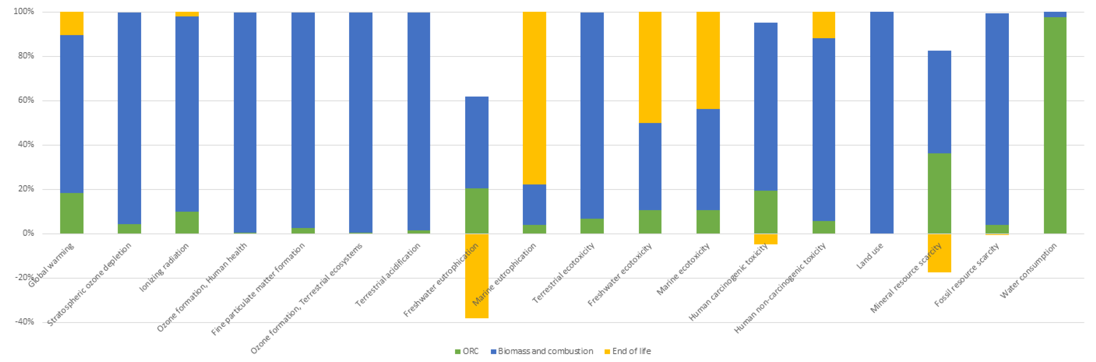
Table 4 summarises the impacts computed with the ReCiPe 2016 method for the operation at full electric load, while Figure 3 depicts the contribution of the different operations on the overall impact.
Focusing on global warming, total emissions of climate-changing gases are equal to 85.2 g CO2,eq/kWh; a value definitively lower than that of the production from fossil fuels, which is estimated around 500 g CO2,eq/kWh for the Italian fossil mix [60].
Note that the organic fluid leakages in the ORC affects this value for about 18.6%. Then, greater attention needs to be paid to this aspect because a better management of the leakages can remarkably improve the impact.
The recycling of steel and copper gives an appreciable positive impact on the mineral resource scarcity and Freshwater Eutrophication.
A large amount of water is required; but, for about 98% it is computable to the water evaporation in the cooling tower.
For many categories, biomass constitutes the major impact. This fact is related to the transportation of wood and tinder, while combustion is responsible for ODP and ecotoxicity high values due to the release of particulate emissions and ash.
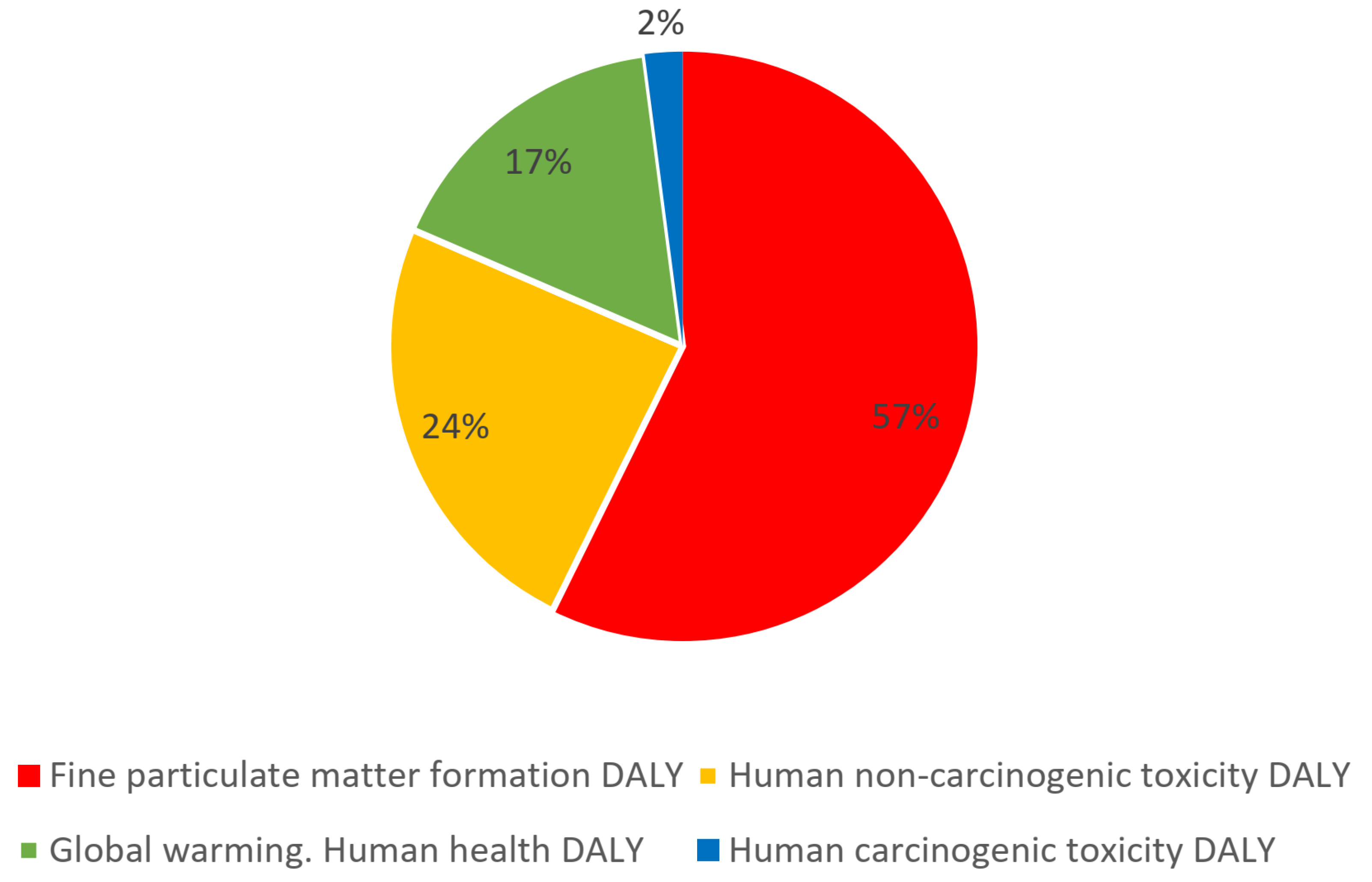
Figure 4 summarizes the results of the ReCiPe Endpoint (H) method and shows the shares of different impacts on Human Health. It is clear that the emissions of particulate matter are the most impacting factor, followed by the non-carcinogenic and climate change emissions. All these emissions are mainly related to the combustion of biomass, and secondarily to the ash management.
Similar results are obtained in [61], where emissions related to the combustion and the transport process of the biomass have the largest share on overall plant impact.
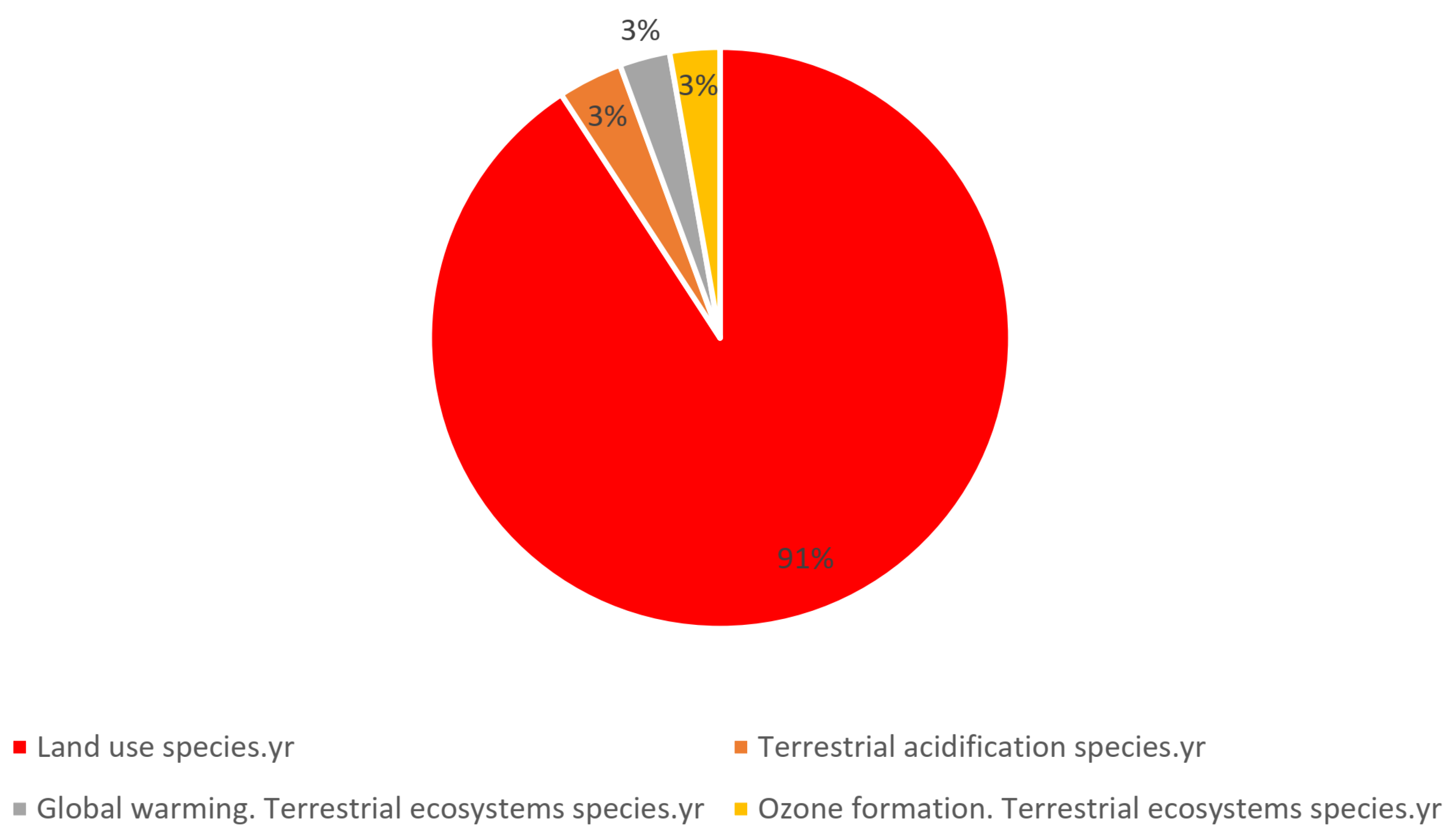
The shares of different impacts on the ecosystem are reported in Figure 5. In this case, the land consumption linked to biomass cultivation is absolutely the most important factor.
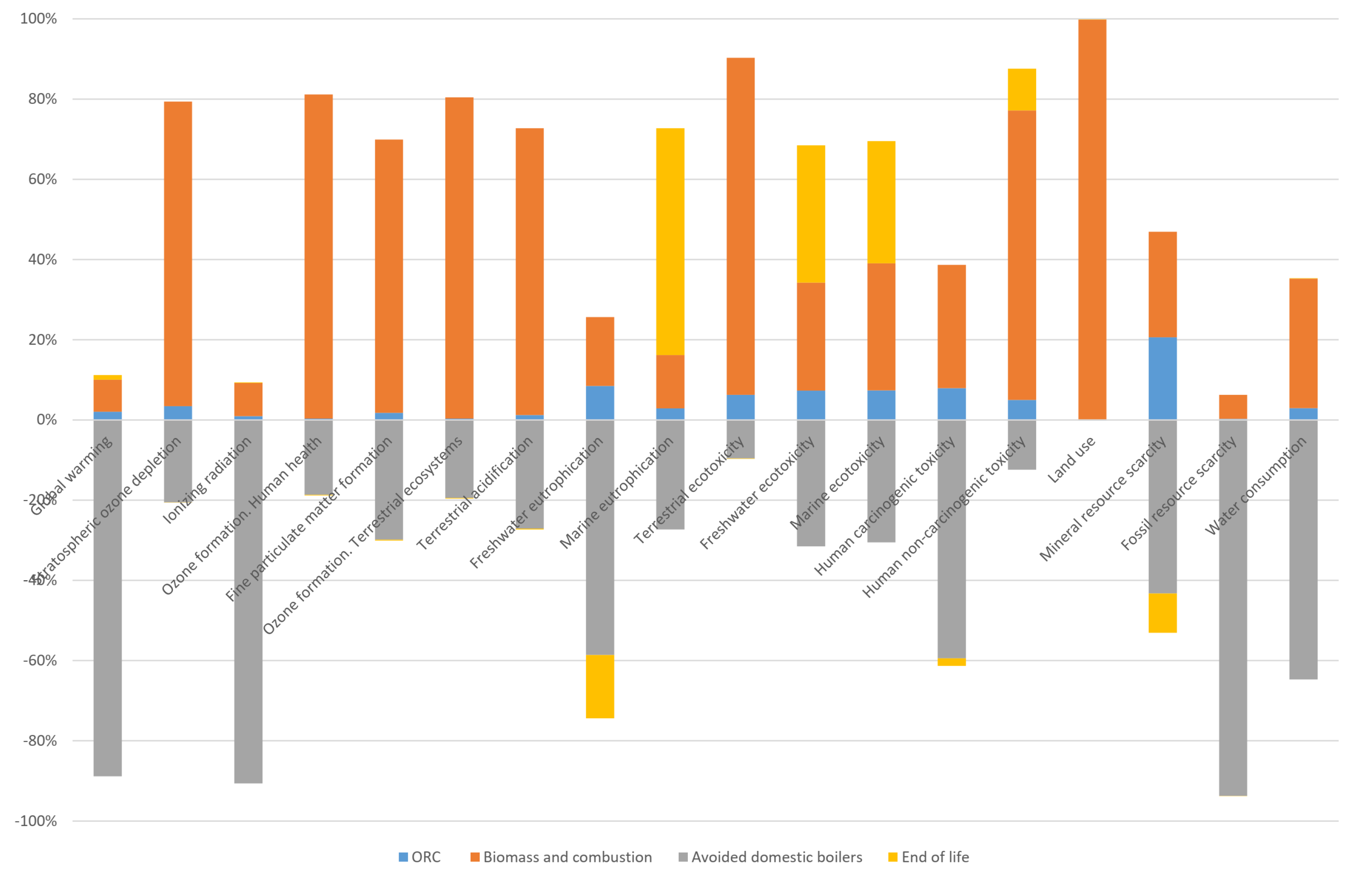
In the case of managing the ORC in CHP mode, the avoided use of domestic boilers needs to be considered in the LCA analysis. Then, as shown in Figure 6, it is clear that managing the unit in CHP mode helps to reduce the overall impact. For many impact categories, the contribution of the ORC system becomes negative because the benefit introduced by the avoided use of natural gas in domestic boilers is higher than the impact generated by the ORC plant.
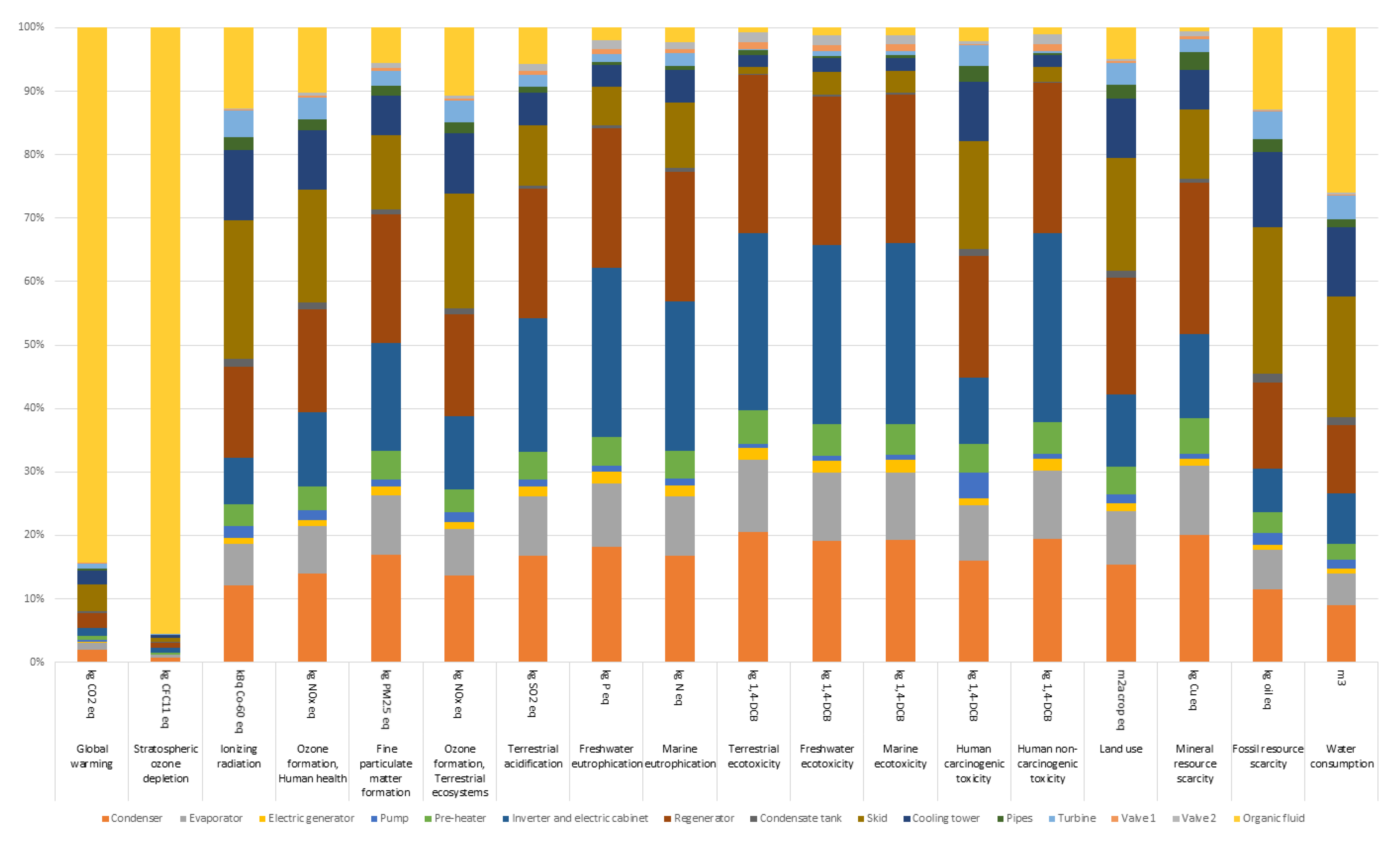
Figure 7 presents a focus on the ORC unit since it does not consider the biomass cultivation and combustion. In particular, the contribution of each device constituting the ORC unit is highlighted. It is clear that the need of an organic fluid is the source of high impact for two categories: Climate Change and Ozone Depletion, while the skid, the regenerator and the condenser exhibit a high-impact on a large number of categories due to the involvement of high mass of materials used to build these components.
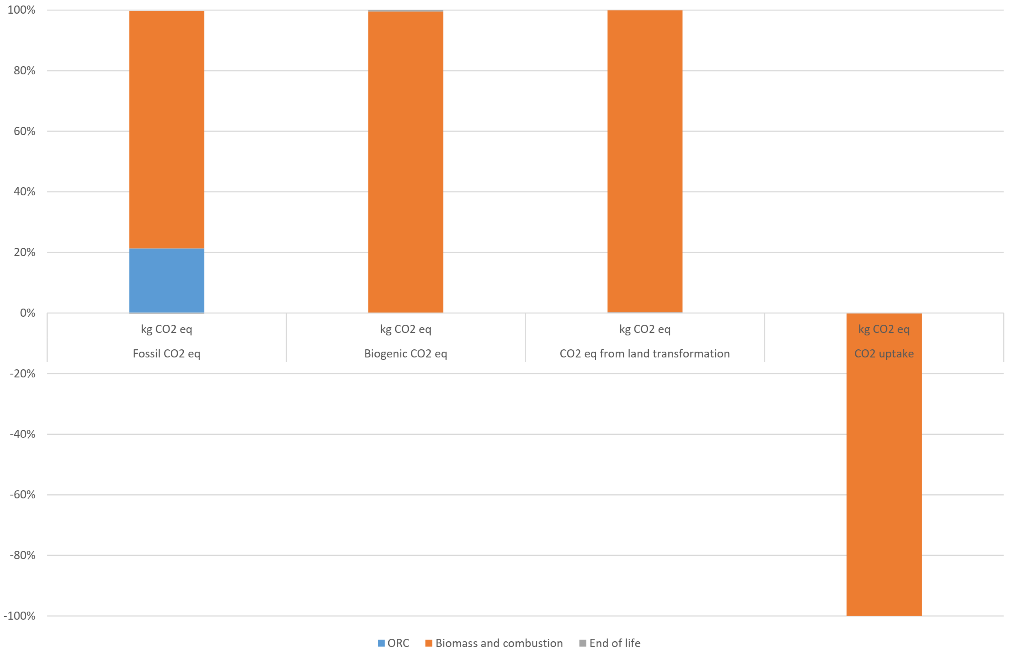
Focusing on carbon footprint (see Figure 8 and Table 5), the impact of the combustion is clearly predominant as regards the biogenic carbon dioxide equivalent emitted, but biomass has a large impact also as regards to the emission of fossil carbon dioxide, which is of greater interest. Although the contribution of this phase is still prevalent, it accounts only for 79%; 21% of the emissions are instead determined by the production, assembly, disposal of the ORC module and by the discharge of part of the organic fluid into the atmosphere.
For a full grasp of these specific simulation outcomes, it is important to underline that “biomass and combustion” component includes, besides combustion, the phase of cultivation, processing and transport of biomass, boiler construction and use of pollutant abatement systems.
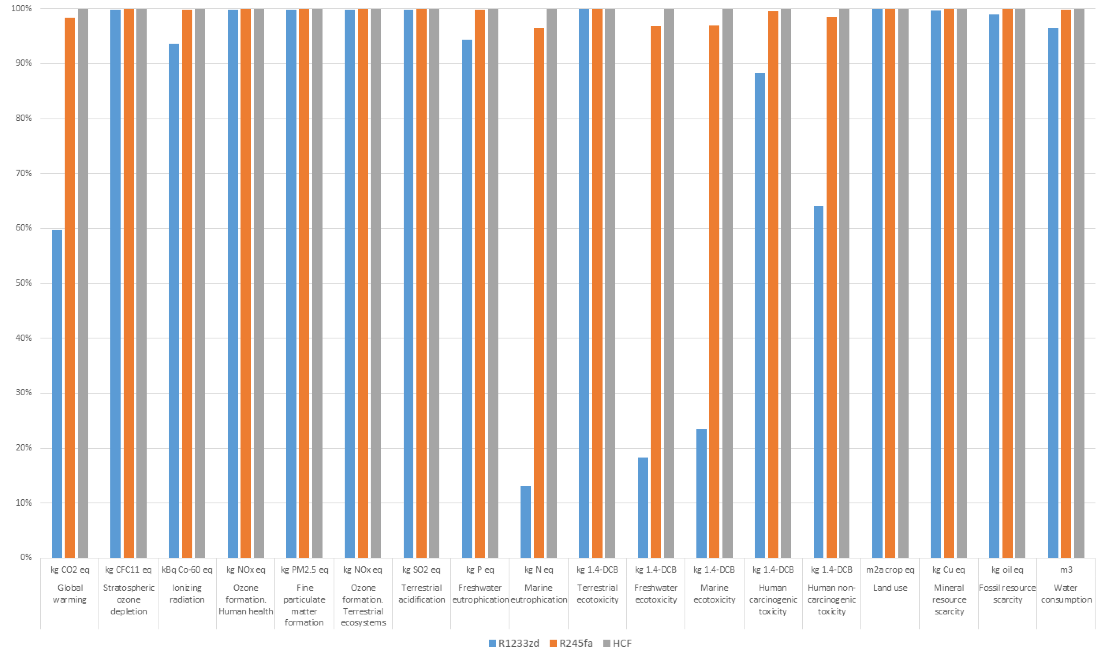
In order to evaluate the possibility of improving the life cycle performances of the system, as suggested by other researchers (see, e.g., [41]), the LCA analysis needs to be performed adopting also different organic fluids. In this analysis, R245fa and R1233zd are selected and their behavior compared to the “HCF” fluid originally used in the ORC unit.
Both fluids are characterized by an ODP equal to 0 as in the case of “HCF”. The GWP amounts to 1030 in the case of R245fa (8.4% higher than the one of the actually adopted fluid) while it is equal to 1 for R1233zd (950 times lower than the “HCF” one). R1233zd is a low GWP fluid design to substitute R123 but it still constitutes a valid replacement to R245fa. A preliminary simulation of the ORC permits to evaluate the efficiency of the cycle with the new fluids and their required amounts.
Figure 9 summarizes the results obtained with the ReCiPe 2016 method. It is clear that for some categories, such as climate change and ecotoxicity, the impact using R1233zd is really reduced. Thus, this fluid guarantees the same energetic performance of the “HCF” but an absolutely lower impact on the entire set of impacts categories.
These results are in agreement with Ref. [41], which studies a geothermal ORC plant. Obviously, the comparison between the authors and reference outcomes is not simple since a geothermal plant needs a lot of infrastructures, very impacting on the environment, which are not necessary when biomass is used. On the other hand, a geothermal unit does not require combustion and continuous biomass consumption which in turn, means continuous biomass cultivation and transportation to the site. In addition, the ORC lifetime estimation for the two plants is very different.
In any case, the improvement of the climate change impact obtained using R1233zd fluid instead of R245fa in the present analysis is about 60 g CO2/kWh which is similar to the value obtained in Ref. [41].
In addition, also in Ref. [41] the analysis confirms that the other impact categories are marginally modified by the use of different fluids.
Lastly, the CED method shows that for each kWh of electricity, the system uses about 7.3 kWh of biomass, but also about 0.24 kWh of fossil fuels, mainly due to the need of Diesel for biomass transportation, chipping and harvesting.
5. Conclusions
Renewable energy sources and energy efficiency are considered the most useful ways to tackle climate change and shift towards a low-carbon economy.
To this purpose, economic supports have been established throughout the years and the main outcome is the widespread of renewable plants, while energy efficiency still lacking especially in the renewable energy sources field.
Among renewables, biomass and, in particular, solid biomass like woodchip, constitutes a valid option to generate electricity, heat or a combination of them due to high fuel supplies programmability and boilers efficiency.
In the energy efficiency sector, the organic Rankine cycle is a consolidate technology which guarantees good efficiency and high reliability.
Therefore, biomass boilers coupled with organic Rankine cycles are a viable option that guarantees to generate electricity and heat.
Despite biomass renewability and ORC unit capability of recovering the waste heat coming from biomass combustion products, it is mandatory to examine system environmental impact taking into account for the fuel supply chain and impacts on the environment caused by organic fluid losses linked to plant leakages.
To this purpose and by means of the lifecycle assessment method, the authors study the environmental impacts of a system composed by a biomass boiler and a 150 kW cogenerative ORC unit.
The analysis is not based on simulation results, but on data collected during five years of plant operation. This aspect is crucial when a life cycle approach is used.
Results show that the most impacting processes in terms of CO2 equivalent emissions are the ones related to biomass production and organic fluid leakages. They accounted for 71% and 19% of the total, respectively.
Therefore, being fluid release into the environment high impacting, a comparison among three fluids are also performed and presented.
The analysis reveals that adopting R1233zd instead of the hydrocarbons fluid actually mounted in the cycle guarantees an improvement in all the impact categories but especially in the climate change one.
It is also finally important to remark that the CED method shows that for each kWh of electricity, the system composed by a biomass boiler and an ORC uses about 7.3 kWh of biomass and approximately 0.24 kWh of fossil fuels because there is the need of Diesel fuel for biomass transportation, chipping and harvesting.
In future works, the analysis will be extended to different in-operation plants based on the same commercial ORC unit. This is fundamental to evaluate how different management strategies, for example related to the transport and the cultivation of biomass or to CHP mode, can affect the overall impact of the plant.
Author Contributions
Conceptualization, A.S. and A.B.; data curation, A.S. and A.B.; investigation, A.S. and A.B.; writing—original draft, A.B.; writing—review and editing, A.S. and A.B. All authors have read and agreed to the published version of the manuscript.
Funding
This research received no external funding.
Conflicts of Interest
Authors declare no conflict of interest.
Nomenclature
| 1.4-DCB | 1.4-DICHLOROBENZENE |
| CFC11 | Trichlorofluoromethane |
| CHP | Combined Heat and Power |
| CO2 | Carbon Dioxide |
| Cu | Copper |
| eq | equivalent |
| EU | European Union |
| g | gramme |
| GHG | Green House Gases |
| GT | Gas Turbine |
| GWP | Global Warming Potential |
| HCF | hydrocarbons fluid |
| ICE | Internal Combustion Engine |
| kBq Co-60eq | kilobecquerels of cobalt-60 equivalents |
| kg | kilogramme |
| LCA | Life Cycle Assessment |
| N | Nitrogen |
| NOx | Nitrogen Oxide |
| ODP | Ozone Depletion Potential |
| ORC | Organic Rankine Cycle |
| P | Phosphorus |
| PM | Particulate Matter |
| RES | Renewable Energy Sources |
| SO2 | Sulphur Dioxide |
| SRC | Steam Rankine Cycle |
| WHRU | Waste Heat Recovery Unit |
References
- BP. BP Statistical Review of World Energy 2018; BP: London, UK, 2018. [Google Scholar]
- International Energy Agency. World Energy Outlook 2018 Summary; Technical report; International Energy Agency: Paris, France, 2018. [Google Scholar] [CrossRef]
- International Renewable Energy Agency (IRENA). Global Energy Transformation: A Roadmap to 2050; International Renewable Energy Agency: Abu Dhabi, UAE, 2018. [Google Scholar] [CrossRef]
- European Parliament and Council of the European Union. Directive 2009/28/EC of the European Parliament and of the Council of 23 April 2009 on the Promotion of the Use of Energy from Renewable sources and Amending and Subsequently Repealing Directives 2001/77/EC and 2003/30/EC; European Commission: Brussels, Belgium, 2009. [Google Scholar]
- European Council. 2030 Framework for Climate and Energy Policies; European Commission: Brussels, Belgium, 2014. [Google Scholar]
- European Council. EU Roadmap 2050; European Commission: Brussels, Belgium, 2010. [Google Scholar]
- Stoppato, A.; Benato, A.; Mirandola, A. Assessment of stresses and residual life of plant components in view of life-time extension of power plants. In Proceedings of the 25th International Conference on Efficiency, Cost, Optimization, Simulations and Environmental Impact of Energy Systems (ECOS 2012), Perugia, Italy, 26–29 June 2012. [Google Scholar]
- Benato, A.; Stoppato, A.; Bracco, S. Combined cycle power plants: A comparison between two different dynamic models to evaluate transient behaviour and residual life. Energy Convers. Manag. 2014, 87, 1269–1280. [Google Scholar] [CrossRef]
- Benato, A.; Stoppato, A.; Mirandola, A. Dynamic behaviour analysis of a three pressure level heat recovery steam generator during transient operation. Energy 2015, 90, 1595–1605. [Google Scholar] [CrossRef]
- Benato, A.; Stoppato, A. Pumped Thermal Electricity Storage: A technology overview. Therm. Sci. Eng. Prog. 2018, 6, 301–315. [Google Scholar] [CrossRef]
- Benato, A.; Stoppato, A. Energy and cost analysis of an Air Cycle used as prime mover of a Thermal Electricity Storage. J. Energy Storage 2018, 17, 29–46. [Google Scholar] [CrossRef]
- Benato, A.; Stoppato, A. Integrated Thermal Electricity Storage System: Energetic and cost performance. Energy Convers. Manag. 2019, 197, 111833. [Google Scholar] [CrossRef]
- Benato, A.; Stoppato, A. Energy and Cost Analysis of a New Packed Bed Pumped Thermal Electricity Storage Unit. J. Energy Resour. Technol. Trans. ASME 2018. [Google Scholar] [CrossRef]
- Benato, A.; Stoppato, A. Heat transfer fluid and material selection for an innovative Pumped Thermal Electricity Storage system. Energy 2018, 147, 155–168. [Google Scholar] [CrossRef]
- Park, H.; Baldick, R. Integration of compressed air energy storage systems co-located with wind resources in the ERCOT transmission system. Int. J. Electr. Power Energy Syst. 2017, 90, 181–189. [Google Scholar] [CrossRef]
- Benato, A. Performance and cost evaluation of an innovative Pumped Thermal Electricity Storage power system. Energy 2017, 138, 419–436. [Google Scholar] [CrossRef]
- Benato, A.; Stoppato, A.; Mirandola, A. State-of-the-art and future development of sensible heat thermal electricity storage systems. Int. J. Heat Technol. 2017, 35, S244–S251. [Google Scholar] [CrossRef]
- WBA. Global Bioenergy Statistics 2018; Technical Report; WBA: West Bromwich, UK, 2018. [Google Scholar]
- Pereira, R.G.; Oliveira, C.D.; Oliveira, J.L.; Oliveira, P.C.P.; Fellows, C.E.; Piamba, O.E. Exhaust emissions and electric energy generation in a stationary engine using blends of diesel and soybean biodiesel. Renew. Energy 2007. [Google Scholar] [CrossRef]
- Benato, A.; Macor, A. Italian Biogas Plants: Trend, Subsidies, Cost, Biogas Composition and Engine Emissions. Energies 2019, 12, 979. [Google Scholar] [CrossRef] [Green Version]
- Chiaramonti, D.; Rizzo, A.M.; Spadi, A.; Prussi, M.; Riccio, G.; Martelli, F. Exhaust emissions from liquid fuel micro gas turbine fed with diesel oil, biodiesel and vegetable oil. Appl. Energy 2013. [Google Scholar] [CrossRef]
- Benato, A.; Macor, A.; Rossetti, A. Biogas Engine Emissions: Standards and On-Site Measurements. Energy Procedia 2017, 126, 398–405. [Google Scholar] [CrossRef]
- Nikpey Somehsaraei, H.; Mansouri Majoumerd, M.; Breuhaus, P.; Assadi, M. Performance analysis of a biogas-fueled micro gas turbine using a validated thermodynamic model. Appl. Therm. Eng. 2014. [Google Scholar] [CrossRef]
- Benato, A.; Macor, A. Biogas Engine Waste Heat Recovery Using Organic Rankine Cycle. Energies 2017, 10, 327. [Google Scholar] [CrossRef]
- Macor, A.; Benato, A. Experimental Measurements and Damage Assessment on Human Health. Energies 2020, 13, 1044. [Google Scholar] [CrossRef] [Green Version]
- Vélez, F.; Segovia, J.J.; Martin, M.C.; Antolin, G.; Chejne, F.; Quijano, A. A technical, economical and market review of organic Rankine cycles for the conversion of low-grade heat for power generation. Renew. Sustain. Energy Rev. 2012, 16, 4175–4189. [Google Scholar] [CrossRef]
- Benato, A.; Stoppato, A.; Mirandola, A. Renewable Energy Conversion and Waste Heat Recovery Using Organic Rankine Cycles. In Renewable Energy Systems; Kale, S.A., Ed.; Nova Science Publishers: Hauppauge, NY, USA, 2016; Chapter 11. [Google Scholar]
- Bianchi, M.; De Pascale, A. Bottoming cycles for electric energy generation: Parametric investigation of available and innovative solutions for the exploitation of low and medium temperature heat sources. Appl. Energy 2011, 88, 1500–1509. [Google Scholar] [CrossRef]
- Pezzuolo, A.; Benato, A.; Stoppato, A.; Mirandola, A. The ORC-PD: A versatile tool for fluid selection and Organic Rankine Cycle unit design. Energy 2016, 102, 605–620. [Google Scholar] [CrossRef]
- Benato, A. Improving the efficiency of a cataphoresis oven with a cogenerative organic Rankine cycle unit. Therm. Sci. Eng. Prog. 2018, 5, 182–194. [Google Scholar] [CrossRef]
- Pezzuolo, A.; Benato, A.; Stoppato, A.; Mirandola, A. Recovering gas turbine high-temperature exhaust heat using organic Rankine cycle with mixture as working fluid. In Proceedings of the 29th International Conference on Efficiency, Cost, Optimization, Simulations and Environmental Impact of Energy Systems (ECOS 2016), Portoroz, Slovenia, 19–26 June 2016. [Google Scholar]
- Campana, F.; Bianchi, M.; Branchini, L.; De Pascale, A.; Petto, A.; Baresi, M.; Fermi, A.; Rossetti, N.; Vescovo, R. ORC waste heat recovery in European energy intensive industries: Energy and GHG savings. Energy Convers. Manag. 2013, 76, 244–252. [Google Scholar] [CrossRef]
- Branchini, L.; De Pascale, A.; Peretto, A. Systematic comparison of {ORC} configurations by means of comprehensive performance indexes. Appl. Therm. Eng. 2013, 61, 129–140. [Google Scholar] [CrossRef]
- Cavazzini, G.; Bari, S.; Pavesi, G.; Ardizzon, G. A multi-fluid PSO-based algorithm for the search of the best performance of sub-critical Organic Rankine Cycles. Energy 2017. [Google Scholar] [CrossRef]
- Benato, A.; Cavazzini, G.; Bari, S.; Ardizzon, G. ORC pump efficiency estimation and real behaviour under different working fluids. In Proceedings of the 32nd International Conference on Efficiency, Cost, Optimization, Simulation and Environmental Impact of Energy Systems (ECOS 2019), Wrocław, Poland, 23–28 June 2019. [Google Scholar]
- Ancona, M.A.; Bianchi, M.; Branchini, L.; De Pascale, A.; Melino, F.; Orlandini, V.; Ottaviano, S.; Peretto, A.; Pinelli, M.; Spina, P.R.; et al. A Micro-ORC Energy System: Preliminary Performance and Test Bench Development. Energy Procedia 2016. [Google Scholar] [CrossRef]
- Ancona, M.A.; Bianchi, M.; Branchini, L.; Pascale, A.; Melino, F.; Ottaviano, S.; Peretto, A.; Scarponi, L.B. Heat recovery from a liquefied natural gas production process by means of an organic rankine cycle. In Proceedings of the ASME Turbo Expo, Lillestrøm, Norway, 11 June 2018. [Google Scholar] [CrossRef]
- ISO. 14040: Environmental Management–Life Cycle Assessment—Principles and Framework; International Organization for Standardization: Geneva, Switzerland, 2006. [Google Scholar]
- Stougie, L.; Tsalidis, G.A.; van der Kooi, H.J.; Korevaar, G. Environmental and exergetic sustainability assessment of power generation from biomass. Renew. Energy 2018. [Google Scholar] [CrossRef]
- Walsh, C.; Thornley, P. The environmental impact and economic feasibility of introducing an organic Rankine cycle to recover low grade heat during the production of metallurgical coke. J. Clean. Prod. 2012. [Google Scholar] [CrossRef]
- Liu, C.; He, C.; Gao, H.; Xie, H.; Li, Y.; Wu, S.; Xu, J. The environmental impact of organic Rankine cycle for waste heat recovery through life-cycle assessment. Energy 2013. [Google Scholar] [CrossRef]
- Heberle, F.; Schifflechner, C.; Brüggemann, D. Life cycle assessment of Organic Rankine Cycles for geothermal power generation considering low-GWP working fluids. Geothermics 2016. [Google Scholar] [CrossRef]
- Lin, Y.P.; Wang, W.H.; Pan, S.Y.; Ho, C.C.; Hou, C.J.; Chiang, P.C. Environmental impacts and benefits of organic Rankine cycle power generation technology and wood pellet fuel exemplified by electric arc furnace steel industry. Appl. Energy 2016. [Google Scholar] [CrossRef]
- Uusitalo, A.; Uusitalo, V.; Grönman, A.; Luoranen, M.; Jaatinen-Värri, A. Greenhouse gas reduction potential by producing electricity from biogas engine waste heat using organic Rankine cycle. J. Clean. Prod. 2016. [Google Scholar] [CrossRef]
- Sedpho, S.; Sampattagul, S.; Chaiyat, N.; Gheewala, S.H. Conventional and exergetic life cycle assessment of organic rankine cycle implementation to municipal waste management: The case study of Mae Hong Son (Thailand). Int. J. Life Cycle Assess. 2017. [Google Scholar] [CrossRef]
- Monteleone, B.; Chiesa, M.; Marzuoli, R.; Verma, V.K.; Schwarz, M.; Carlon, E.; Schmidl, C.; Ballarin Denti, A. Life cycle analysis of small scale pellet boilers characterized by high efficiency and low emissions. Appl. Energy 2015. [Google Scholar] [CrossRef]
- Singh, P.; Gundimeda, H.; Stucki, M. Environmental footprint of cooking fuels: A life cycle assessment of ten fuel sources used in Indian households. Int. J. Life Cycle Assess. 2014. [Google Scholar] [CrossRef]
- Boschiero, M.; Kelderer, M.; Schmitt, A.O.; Andreotti, C.; Zerbe, S. Influence of agricultural residues interpretation and allocation procedures on the environmental performance of bioelectricity production—A case study on woodchips from apple orchards. Appl. Energy 2015. [Google Scholar] [CrossRef]
- Stoppato, A. Life cycle assessment of photovoltaic electricity generation. Energy 2008. [Google Scholar] [CrossRef]
- Fantinato, D.; Stoppato, A.; Benato, A. LCA analysis of a low-energy residential building. In Proceedings of the 32nd International Conference on Efficiency, Cost, Optimization, Simulation and Environmental Impact of Energy Systems (ECOS 2019), Wrocław, Poland, 23–28 June 2019; pp. 3153–3165. [Google Scholar]
- Toscani, A.; Stoppato, A.; Benato, A. LCA of a concert: Evaluation of the Carbon footprint and of Cumulative energy demand. In Proceedings of the 32nd International Conference on Efficiency, Cost, Optimization, Simulation and Environmental Impact of Energy Systems (ECOS 2019), Wrocław, Poland, 23–28 June 2019; pp. 3203–3213. [Google Scholar]
- Préconsultants. SimaPro 9.0. Available online: https://simapro.com/ (accessed on 8 April 2020).
- Laleman, R.; Albrecht, J.; Dewulf, J. Life cycle analysis to estimate the environmental impact of residential photovoltaic systems in regions with a low solar irradiation. Renew. Sustain. Energy Rev. 2011, 15, 267–281. [Google Scholar] [CrossRef]
- Hung, T.C.; Wang, S.K.; Kuo, C.H.; Pei, B.S.; Tsai, K.F. A study of organic working fluids on system efficiency of an ORC using low-grade energy sources. Energy 2010. [Google Scholar] [CrossRef]
- Qiu, G.; Shao, Y.; Li, J.; Liu, H.; Riffat, S.B. Experimental investigation of a biomass-fired {ORC}-based micro-{CHP} for domestic applications. Fuel 2012, 96, 374–382. [Google Scholar] [CrossRef] [Green Version]
- IPCC. Revised Supplementary Methods and Good Practice Guidance Arising from the Kyoto Protocol, Intergovernmental Panel on Climate Change; Technical Report; IPCC: Geneva, Switzerland, 2013. [Google Scholar]
- Huijbregts, M.; Steinmann, Z.J.N.; Elshout, P.M.F.M.; Stam, G.; Verones, F.; Vieira, M.D.M.; Zijp, M.; van Zelm, R. ReCiPe 2016; National Institute for Public Health and the Environment: Bilthoven, The Netherlands, 2016. [Google Scholar] [CrossRef]
- Frischknecht, R.; Wyss, F.; Büsser Knöpfel, S.; Lützkendorf, T.; Balouktsi, M. Cumulative energy demand in LCA: The energy harvested approach. Int. J. Life Cycle Assess. 2015. [Google Scholar] [CrossRef]
- Schmitz, S.; Dawson, B.; Spannagle, M.; Thomson, F.; Koch, J.; Eaton, R. The Greenhouse Gas Protocol—A Corporate Accounting and Reporting Standard; Revised, Ed.; The GHG Protocol Corporate Accounting and Reporting Standard; World Resources Institute and World Business Council for Sustainable Development: Washington, DC, USA, 2001. [Google Scholar]
- Istituto Superiore per la Protezione e la Ricerca Ambientale. Fattori di emissione per la produzione ed il consumo di energia elettrica in Italia (Emission Factors for Production and Consumption of electricity). Technical Report; 2019. Available online: http://www.sinanet.isprambiente.it/it/sia-ispra/serie-storiche-emissioni/ (accessed on 8 April 2020).
- Stougie, L.; Giustozzi, N.; van der Kooi, H.; Stoppato, A. Environmental, economic and exergetic sustainability assessment of power generation from fossil and renewable energy sources. Int. J. Energy Res. 2018. [Google Scholar] [CrossRef]
Figure 1.
Schematic view of the ORC unit in its Combined Heat and Power (CHP) operation. Data refer to design point operating conditions.
Figure 1.
Schematic view of the ORC unit in its Combined Heat and Power (CHP) operation. Data refer to design point operating conditions.

Figure 2.
Simplified tree representation of the system in the lifecycle assessment. Percentages and lines refer to CO2,eq emissions.
Figure 2.
Simplified tree representation of the system in the lifecycle assessment. Percentages and lines refer to CO2,eq emissions.

Figure 3.
Contribution of operations in full electric mode (ReCiPe 2016 method).

Figure 4.
Contribution to Human Health of different impacts. Results are obtained with ReCiPe 2016—Endpoint (H) method.
Figure 4.
Contribution to Human Health of different impacts. Results are obtained with ReCiPe 2016—Endpoint (H) method.

Figure 5.
Contribution to Ecosystem of different impacts. Results are obtained with ReCiPe 2016—Endpoint (H) method.
Figure 5.
Contribution to Ecosystem of different impacts. Results are obtained with ReCiPe 2016—Endpoint (H) method.

Figure 6.
Contribution of the different operations to the overall impact in CHP mode. Results are obtained with ReCiPe 2016—Midpoint (H) method.
Figure 6.
Contribution of the different operations to the overall impact in CHP mode. Results are obtained with ReCiPe 2016—Midpoint (H) method.

Figure 7.
Contribution on the different impact categories of ORC devices construction and operation. Results are obtained with ReCiPe 2016—Midpoint (H) method.
Figure 7.
Contribution on the different impact categories of ORC devices construction and operation. Results are obtained with ReCiPe 2016—Midpoint (H) method.

Figure 8.
Carbon footprint.

Figure 9.
Comparisons of the life cycle impacts for three different organic fluids. Results are obtained with ReCiPe 2016—Midpoint (H) method.
Figure 9.
Comparisons of the life cycle impacts for three different organic fluids. Results are obtained with ReCiPe 2016—Midpoint (H) method.


Table 1.
Main features of the Organic Rankine Cycle (ORC) module at design conditions.
| Parameters | Unit | Full Electric Mode | CHP Mode |
|---|---|---|---|
| Input thermal power | kW | 1100 | |
| Inlet temperature of the heat transfer fluid (water) | C | ≥160 | |
| Outlet temperature of the heat transfer fluid (water) | C | 140 | |
| Heat transfer fluid (water) mass flow rate | kg/s | 13.14 | |
| Electric power | kW | 150 | 98 |
| Electric efficiency | % | 13.6 | 8.6 |
| Output thermal power | kW | 940 | 1000 |
| Inlet temperature of water for thermal use | C | 26 | 60 |
| Outlet temperature of water for thermal use | C | 36 | 80 |
| Water mass flow rate | kg/s | 22.46 | 11.95 |
Table 2.
Devices of the ORC module.
| Components | Characteristics |
|---|---|
| Pre-heater | Counter-flow brazed plate heat exchanger |
| Evaporator | Counter-flow brazed plate heat exchanger |
| Turbine | Radial turbine with fixed nozzles |
| Electric generator | Brushless synchronous generator with permanent magnets |
| Regenerative heat exchanger | Counter-flow brazed plate heat exchanger |
| Condenser | Counter-flow brazed plate heat exchanger |
| Pump | Centrifugal machine |
Table 3.
Summary of the mass streams of the ORC module.
| Material | Unit | Weight |
|---|---|---|
| Steel | kg | 5320 |
| Brass | kg | 25 |
| Pig iron | kg | 150 |
| Copper | kg | 510 |
| Aluminium alloy | kg | 2 |
| Permanent magnets | kg | 4.32 |
Table 4.
Summary of the mass stream of the ORC module.
| Impact Category | Unit | Total |
|---|---|---|
| Global warming | kg CO2,eq | 0.085283 |
| Stratospheric ozone depletion | kg CFC11eq | 5.53 |
| Ionizing radiation | kBq Co-60eq | 0.001301 |
| Ozone formation. Human health | kg NOx,eq | 0.001811 |
| Fine particulate matter formation | kg PM2.5eq | 0.000439 |
| Ozone formation. Terrestrial ecosystems | kg NOx,eq | 0.00184 |
| Terrestrial acidification | kg SO2,eq | 0.001447 |
| Freshwater eutrophication | kg Peq | 5.83 |
| Marine eutrophication | kg Neq | 8.33 |
| Terrestrial ecotoxicity | kg 1.4-DCB | 1.68345 |
| Freshwater ecotoxicity | kg 1.4-DCB | 0.007768 |
| Marine ecotoxicity | kg 1.4-DCB | 0.01133 |
| Human carcinogenic toxicity | kg 1.4-DCB | 0.002995 |
| Human non-carcinogenic toxicity | kg 1.4-DCB | 0.510964 |
| Land use | m2a cropeq | 0.87156 |
| Mineral resource scarcity | kg Cueq | 0.000275 |
| Fossil resource scarcity | kg oileq | 0.015262 |
| Water consumption | m3 | 0.009958 |
Table 5.
Summary of the carbon footprint.
| Impact Category | g CO2,eq |
|---|---|
| Fossil | 73.2 |
| Biogenic | 1910 |
| from land transformation | 0.89 |
| CO2 uptake | 1900 |
© 2020 by the authors. Licensee MDPI, Basel, Switzerland. This article is an open access article distributed under the terms and conditions of the Creative Commons Attribution (CC BY) license (http://creativecommons.org/licenses/by/4.0/).
Share and Cite
MDPI and ACS Style
Stoppato, A.; Benato, A. Life Cycle Assessment of a Commercially Available Organic Rankine Cycle Unit Coupled with a Biomass Boiler. Energies 2020, 13, 1835. https://0-doi-org.brum.beds.ac.uk/10.3390/en13071835
AMA Style
Stoppato A, Benato A. Life Cycle Assessment of a Commercially Available Organic Rankine Cycle Unit Coupled with a Biomass Boiler. Energies. 2020; 13(7):1835. https://0-doi-org.brum.beds.ac.uk/10.3390/en13071835
Chicago/Turabian StyleStoppato, Anna, and Alberto Benato. 2020. "Life Cycle Assessment of a Commercially Available Organic Rankine Cycle Unit Coupled with a Biomass Boiler" Energies 13, no. 7: 1835. https://0-doi-org.brum.beds.ac.uk/10.3390/en13071835
Note that from the first issue of 2016, this journal uses article numbers instead of page numbers. See further details here.