Article

Differential Flatness Based-Control Strategy of a Two-Port Bidirectional Supercapacitor Converter for Hydrogen Mobility Applications

by
Phatiphat Thounthong
1,*,
Matheepot Phattanasak
1,
Damien Guilbert
2,*,
Noureddine Takorabet
2,
Serge Pierfederici
3,
Babak Nahid-Mobarakeh
4,
Nicu Bizon
5 and
Poom Kumam
6
1
Department of Teacher Training in Electrical Engineering, Renewable Energy Research Centre (RERC), Faculty of Technical Education, King Mongkut’s University of Technology North Bangkok, Bangkok 10800, Thailand
2
Groupe de Recherche en Energie Electrique de Nancy (GREEN), Université de Lorraine, GREEN, F-54000 Nancy, France
3
Laboratoire d’Energétique et de Mécanique Théorique et Appliquée (LEMTA), Université de Lorraine, CNRS, LEMTA, F-54000 Nancy, France
4
Department of Electrical and Computer Engineering, McMaster University, Hamilton, ON L8S 4L8, Canada
5
Faculty of Electronics, Communication and Computers, University of Pitesti, 110040 Pitesti, Romania
6
Faculty of Science, Department of Mathematics, KMUTT Fixed Point Research Laboratory, King Mongkut’s University of Technology Thonburi, Bangkok 10140, Thailand
*
Authors to whom correspondence should be addressed.
Submission received: 11 May 2020 / Revised: 25 May 2020 / Accepted: 28 May 2020 / Published: 1 June 2020
(This article belongs to the Special Issue Advances in Hydrogen and Fuel Cell Systems)

Abstract

:
This article is focused on an original control approach applied to a transportation system that includes a polymer electrolyte membrane fuel cell (PEMFC) as the main energy source and supercapacitors (SC) as the energy storage backup. To interface the SC with the DC bus of the embedded network, a two-port bidirectional DC-DC converter was used. To control the system and ensure its stability, a reduced-order mathematical model of the network was developed through a nonlinear control approach employing a differential flatness algorithm, which is an attractive and efficient solution to make the system stable by overcoming the dynamic issues generally met in the power electronics networks of transportation systems. The design and tuning of the system control were not linked with the equilibrium point at which the interactions between the PEMFC main source, the SC energy storage device, and the loads are taken into consideration by the proposed control law. Besides this, high dynamics in the load power rejection were accomplished, which is the main contribution of this article. To verify the effectiveness of the developed control law, a small-scale experimental test rig was realized in the laboratory and the control laws were implemented in a dSPACE 1103 controller board. The experimental tests were performed with a 1 kW PEMFC source and a 250 F 32 V SC module as an energy storage backup. Lastly, the performances of the proposed control strategy were validated based on real experimental results measured during driving cycles, including motoring mode, ride-though, and regenerative braking mode.

Graphical Abstract

1. Introduction

Eco-friendly and sustainable new power sources have become a research spotlight in the energy subject. The polymer electrolyte membrane fuel cell (PEMFC) converts hydrogen and oxygen into electricity. The PEMFC features a high power generation efficiency, high energy density, quick start-up (due to low-temperature operation), and no pollution (only water is released) during operation, which makes it fit for DC distribution networks including distributed generation and mobility applications [1,2,3]. To face the depletion of fossil fuels and reduce global greenhouse gases, PEMFCs are considered for replacing the internal combustion engine (ICE). Nevertheless, for transportation applications, the use of a unique PEMFC as the main source leads to the decrease in its life span due to the high dynamic solicitations [4]. Indeed, PEMFCs suffer from having a slow dynamic response. Sudden variations in the operating load power request cannot be fully provided by the PEMFC [5,6]. In addition, when the load power demanded is overload or during regenerative operations (braking mode), the PEMFC cannot be used to absorb the excess energy. As a result, the PEMFC system has to be coupled with energy storage devices to enhance the PEMFC lifespan, store the energy surplus, and maintain safe operation processes [7,8]. Several articles have been reported concerning the hybridization between PEMFCs and batteries or supercapacitors (SCs) for transportation applications [9,10,11].
As presented in Figure 1, SCs have been successfully developed as energy storage backups in public transportation applications in both off-board (substation) and on-board systems. Based on SC energy storage, these systems are well known for offering a number of improvements for transportation applications. In particular, these systems have illustrated enhanced efficiency by storing energy recovered from vehicle regenerative braking, which is not possible with either a main power source rectifier or diesel engine alone [12,13,14]. To enable the charge and discharge of the SCs, bidirectional DC-DC converters are requested to ensure the stability of the system during dynamic operations, particularly important in transportation systems. Indeed, when one or several vehicles start at the same time, a large amount of energy is required for a brief time. Hence, the SCs have to be able to quickly release a large amount of energy to avoid the instability of the DC bus. As a result, the DC bus voltage can be kept within a specific operating range. This can effectively decrease losses in production and profits associated with tripping equipment that is sensitive to voltage variations. Therefore, the system does not only save energy but also the high dynamic response time of the SCs prevents unexpected losses in energy for vehicles.
As reported by Maher [15], the first energy storage system that used SC technology in a local transport network was demonstrated in Cologne, Germany, in 2001 (Figure 1b). Godbersen [16] also reported that two SC energy storage units (94 F, 0.7 MW) have been installed in metro networks in Madrid, Spain, in 2002, and similar units were later installed in Dresden, Germany, and Portland, USA. One SC energy storage unit can reduce the annual major energy demand by 500 MWh (around 30%). Moreover, Steiner et al. [17] reported that the Bombardier tram, a light rail vehicle based on an onboard SC energy storage with 1.5 kWh and 518 V (Figure 1c), has been successfully operating in Mannheim, Germany, since 2003, and this system has illustrated possibilities for energy savings of up to 30% compared to light rail vehicles.
In trolleybus applications, many vehicles that are called “Supercapacitor trolleybuses” and based on pure SC sources have been operating in the 5 km-long circular line at the center of Shanghai, China, since 2006 [18]. This SC trolleybus is a cableless and trackless electric vehicle that uses energy stored in onboard SCs. When the trolleybus is stopped at a bus station, the energy storage system can be charged within 30 seconds through a pantograph located on the roof, which is the approximate needed time for passengers to get on and off the bus. However, the stored energy onboard allows the bus to travel the distance between two stations (approximately 500 m).
Bidirectional two-quadrant DC-DC topologies are mandatory to manage the energy flows in transportation applications. Figure 2 displays a classic two-quadrant buck-boost converter based on two bidirectional power switches that is generally employed to interface the energy storage device with the DC bus [19,20,21]. Input (L1) and output filters (L2) are added to reduce current ripples. From the SC side, a discharging unit composed of a thyristor (V2) and a resistor (R2) is employed to protect the SC module against overload. In comparison, from the connection unit side connected to the high DC bus voltage, electronic circuits are used to isolate the converter in case of high currents through the DC circuit breaker and to pre-charge the SC. The main disadvantage of using this classic buck-boost converter is its limited voltage ratio and, consequently, it can be used for applications requiring step-up ratios and higher power. A two-port bidirectional DC/DC topology with a ground-isolated transformer is a superior scheme to obtain safe ground isolation and a high dc voltage value [22,23].
Recently, the research works on the small-signal and large-signal stabilities of DC-DC converters have become one of the main significant and complex topics in the field of electrical engineering. In 1995, the differential flatness approach was proposed by Fliess et al. [24]. Based on this work carried out by Fliess et al. [24], the differential flatness control strategy has been employed successfully in several works to control power electronics and manage energy flows in embedded applications [25,26,27,28,29,30,31,32]. In [25], the differential flatness control is applied to the unmanned aerial vehicle to solve trajectory planning issues, whereas in [26], this control is used in a stand-alone power supply to manage different sources (i.e., fuel cell (FC), batteries, and SCs) connected to classic converters (i.e., boosts for the FC and buck-boosts for the energy storage devices). In comparison, in [27] the authors have employed the differential flatness theory to control an output series interleaved DC-DC boost converter for FC applications, while in [31] it is used to manage a distributed generation hybrid system based on FC and SC connected respectively to four-phase boost and buck-boost converters. In [28,29,30], the control of the AC-DC converter and DC-AC converters supplying permanent magnet synchronous motors is based on a differential flatness approach. Finally, in [32] the control of a two-phase interleaved buck-boost converters connected to energy storage devices (i.e., batteries and SC) and the stability of the DC bus in a hybrid electric vehicle is ensured by the use of this nonlinear control.
For clarity, as presented by Thounthong et al. [31], Figure 3 demonstrates an experimental comparison of the basic proportional–integral (PI) control and flatness-based control algorithms to ensure a DC bus voltage stabilization of 60 V in a PEMFC/SC hybrid power source to face a load power. It can be noted that the DC bus voltage is quite low compared to the usual DC bus voltage (i.e., hundreds of volts), as reported in [8,15,16,17,18]. In the previous work [31], a distributed generation system was developed including a PEMFC source and an SC bank that interface with the DC bus using a four-phase interleaved boost and a four-phase interleaved buck-boost converter, respectively. Since their voltage gains are limited and to enhance the efficiency of both converters, a conversion gain of around two was chosen. For this reason, the DC bus voltage is equal to 60 V.
The parameters of the PI controller have been tuned to achieve excellent dynamics performance, with the preferred phase margin (PM) = 30° and 60°. The proposed flatness control law demonstrates good dynamics and excellent response for the control of the DC bus to its desired 60 V set point. From these results, it can be concluded that the differential flatness control approach enables offering better performance over basic linear PI controllers.
This paper presents the characteristics and conception of the PEMFC hybrid power source in mobility networks including SCs as the energy storage backup. Compared to the previous works reported in the literature and related to this research topic [26,31,32], the PEMFC is directly connected to the DC bus without using a step-up DC-DC converter (i.e., boost or interleaved boost converter) and a two-port bidirectional DC/DC topology is used to manage the operation of the SCs. Hence, the DC bus voltage is not constant and may change according to the operating conditions. In this work, only the PEMFC and SC voltages are considered as variables to protect PEMFC against degradation and manage the SC operation in a suitable operating voltage range. As a result, the main contribution of this article is to ensure the stability and the balance of the DC bus, taking into consideration the PEMFC and SC operating voltage range through the control based on the differential flatness approach of a two-port bidirectional DC/DC converter.
The article is composed of five sections: after introducing the previous works on this topic and the main reasons to carry out this work, Section 2 presents the SC energy storage for PEMFC mobility applications, the studied SC converter based on a dual-active bridge topology, and the simplified studied system using a reduced-order model. Then, in Section 3 the developed energy management including the control laws and stability proof is provided. After that, in Section 4 the experimental test rig is described and the obtained results are given and analyzed. Finally, in Section 5 all the results are discussed and some perspectives are provided as well for future works.

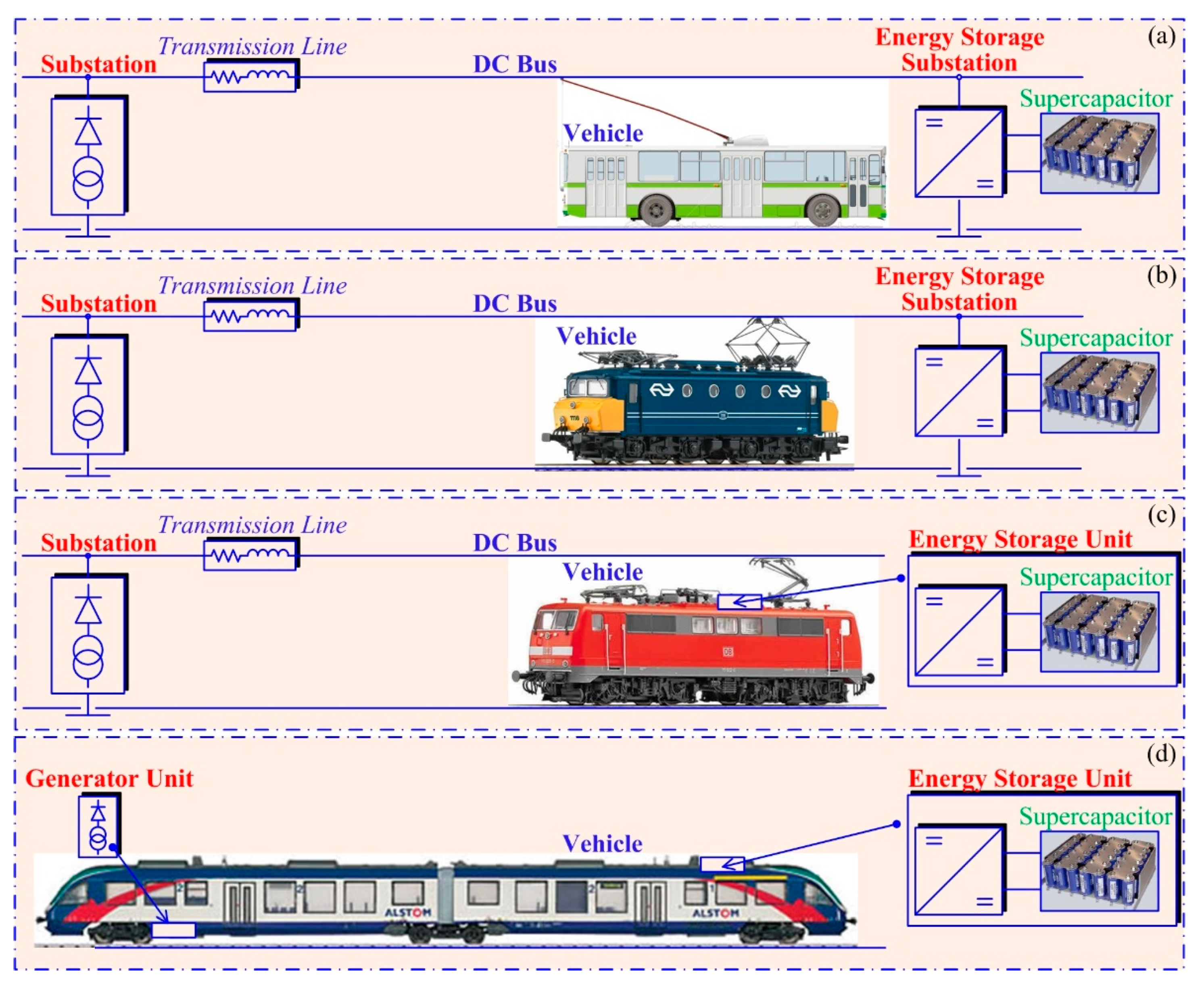
2. Supercapacitor-Based Energy Storage for PEMFC Mobility Applications

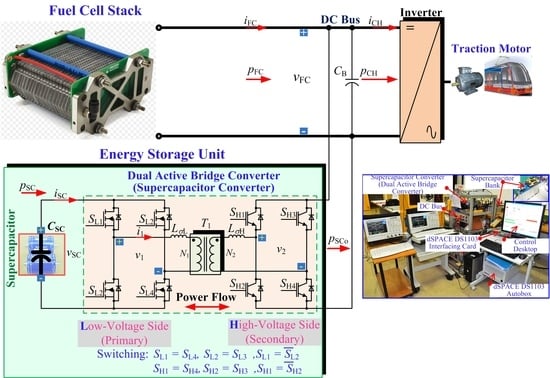
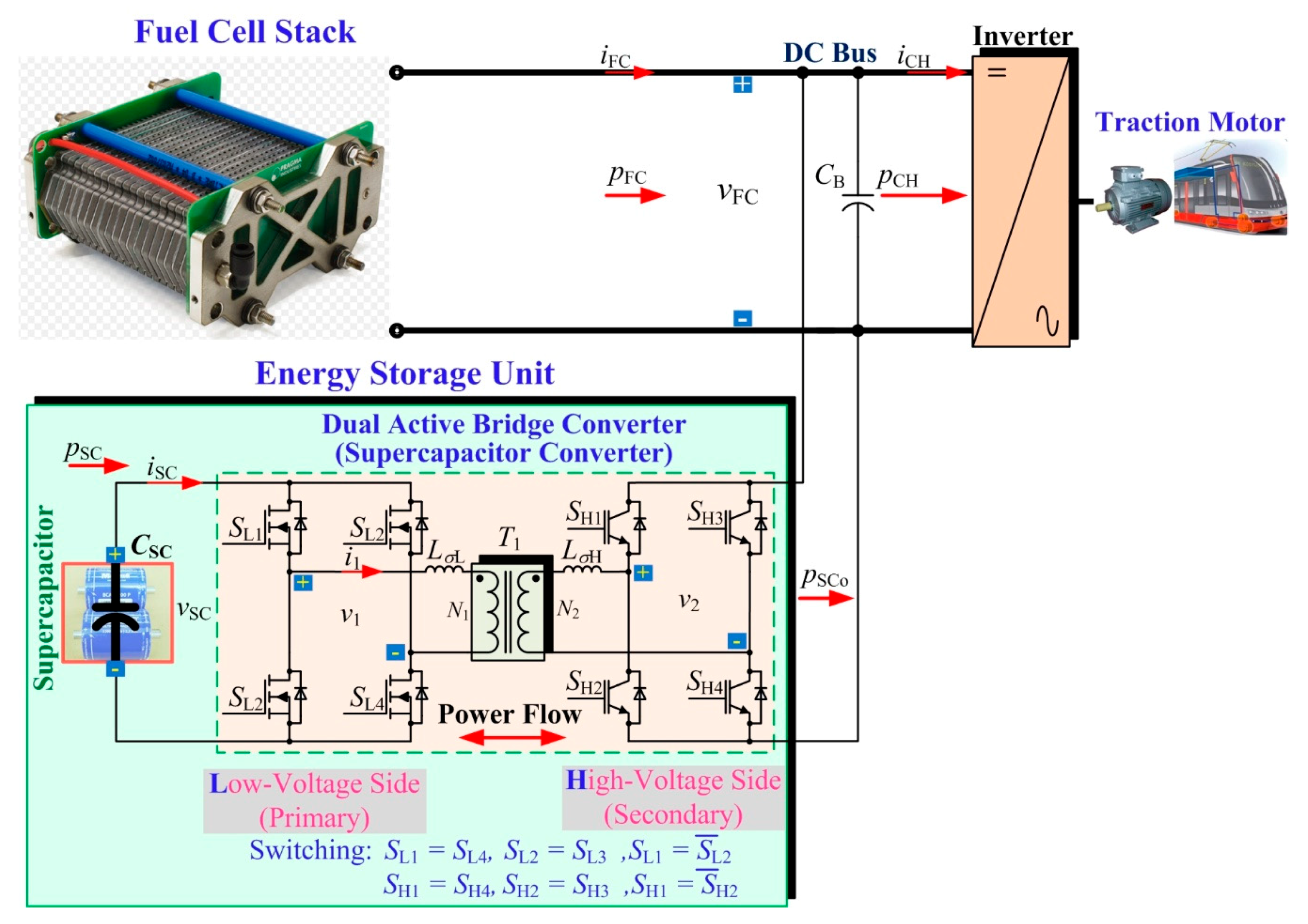
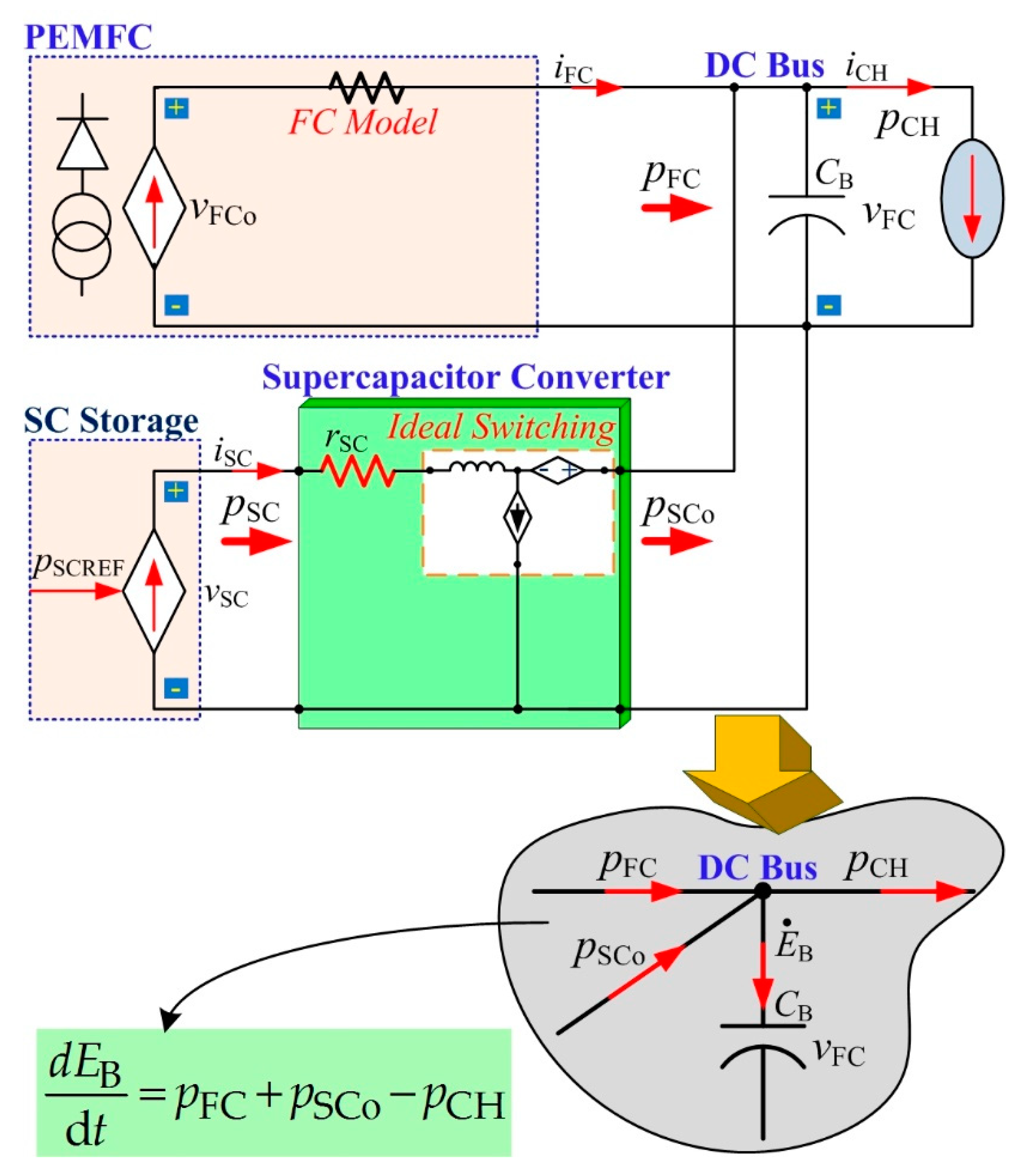
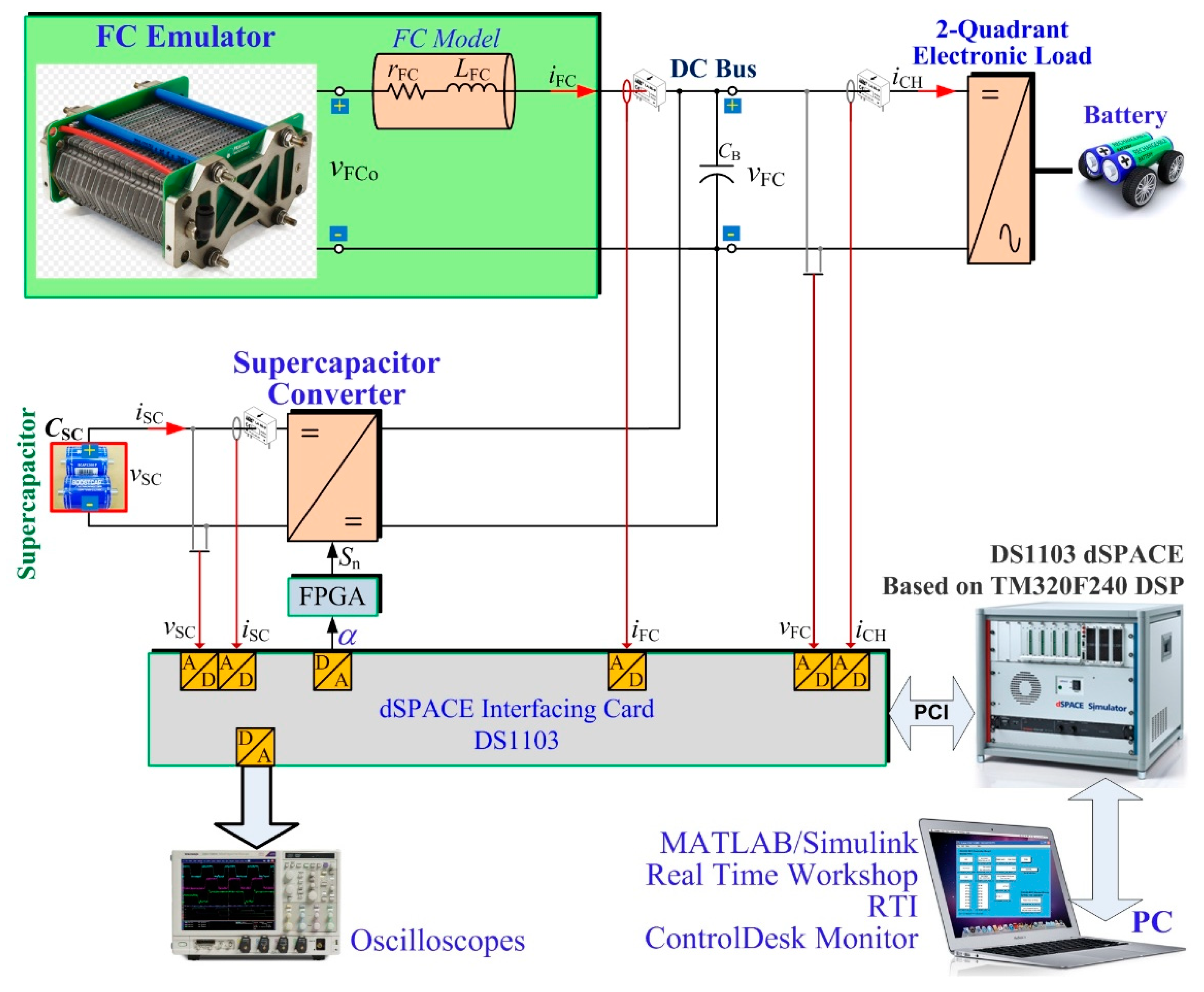
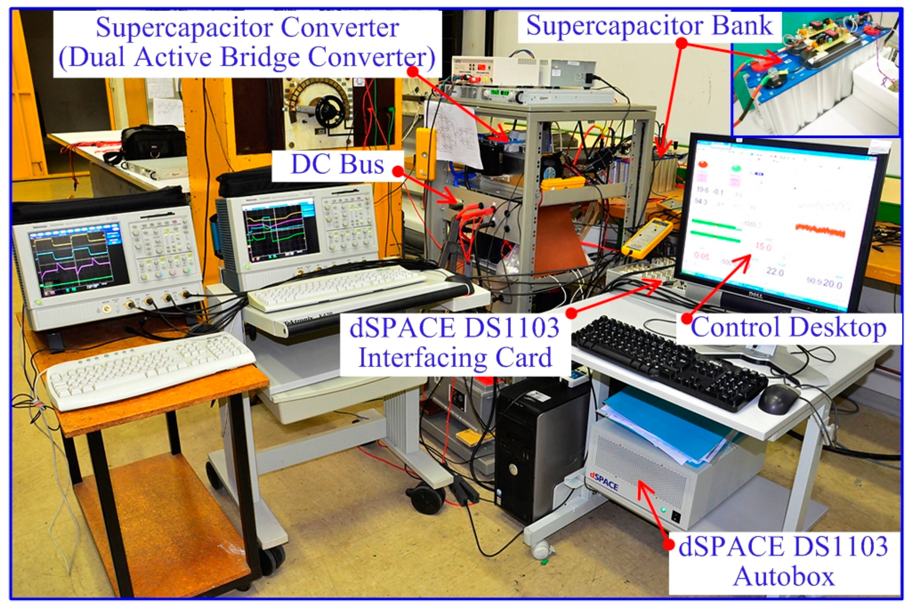
2.1. System Description

For embedded networks based on FC and SC for mobility applications (Figure 1), two variables have to be taken into consideration for control purposes as follows:
(1) The control of the PEMFC voltage vFC is crucial to avoid operations below the acceptable voltage value for the vehicle, which would impede the delivery of the maximum power of the FC main source PFCMax. Indeed, in the PEMFC polarization curves the higher the load current, the lower the stack voltage of the PEMFC. In our application, a higher power request (i.e., acceleration mode) would lead to a decrease in the PEMFC voltage. Generally, the maximum power that a PEMFC can supply is obtained at rated stack voltage. Under this voltage value (i.e., concentration region), the available PEMFC power decreases and this leads to the degradation of the stack [2,26]. For this reason, to take advantage of the main power source the PEMFC has to operate in a specific voltage range, as shown in Figure 4. In summary, to take advantage of the PEMFC to meet the load power demand, a large range voltage has been adopted from a maximum voltage at no-load current to the minimum voltage-reached nominal power.
(2) The second variable to control concerns the SC voltage vSC (or energy ESC) related to the charge and discharge of the SC. As displayed in Figure 5, the SC voltage has to be included in a specific voltage operation range (VSCMin, VSCMax). Indeed, VSCMax is the SC maximum permitted voltage, and operations over this permitted value could damage the device. This voltage is generally provided by the manufacturer of the SC modules.
In comparison, the minimum permitted voltage VSCMin is defined as the current capability of the power converter and SC. Usually, VSCMax/2 is given as the VSCMin value and corresponds to a state-of-charge (SOC) of 25%. By limiting the SOC, it allows ensuring a good operation of the charging/discharging cycles, as recommended by SC manufacturers.
The nominal voltage VSCNom corresponds to a SOC of 100% (fully charged). As discussed in [33], the nominal voltage VSCNom can be included between VSCMin and VSCMax and is strongly dependent on the design requirements (ratio between the braking energy ability and ride-through energy availability).
The control aspects mentioned in this paragraph will be explained in the following section. The system operating modes are briefly discussed in the following. As shown in Figure 6, vehicles may operate in three different operating modes (i.e., motoring the main supply or ride-through, regenerative braking). Motoring the main supply mode means that only the power supply from the substation is used, whereas in motoring ride-through mode, an additional energy source such as SC is required to supply power to the vehicles, ensuring consequently the stability of the substation. In this case, SCs are in discharging mode. Finally, the last operating mode concerns the absorption of the available energy during regenerative braking, enabling consequently the recharging of the SCs. These operating modes can be summarized by these main phases: (1) stop at the station (motoring main supply); (2) start-up of the vehicle, requesting sudden high power (motoring ride-through); (3) steady-state operating between two stops as a result of the start-up operating (motoring main supply); and, finally, (4) the regenerative braking of the vehicle before stopping at the next station.
Figure 6 illustrates experimental data (i.e., DC bus voltage, SC current, and SC SOC) coming from a metro de Madrid based on SCs [16]. The DC bus voltage range is included between 510 V (minimum level) and 700 V (maximum voltage) to avoid the overload and unbalance of the electrical transmission line. The nominal DC bus voltage is set to 600 V. At t0, the initial operating condition of the metro is in “motoring mode”, meaning that the SOC of SC is equal to 100% (completely charged). Therefore, the main power source supplies power to the metro. At t1, the DC bus voltage vBus falls to a minimum value of 510 V due to simultaneous acceleration by several vehicles. As a result, the storage device began stabilizing the DC bus voltage. Here, the SC discharged (positive current) and supplied enough power to maintain the DC bus voltage at a limited minimum voltage of 510 V. This mode is commonly called “motoring mode: ride-through”. In this mode, both the main substation and SC substation supply power to meet the power request from the load, and the energy storage system continuously discharges until t2. As soon as the instantaneous acceleration of the vehicle ends, the DC bus voltage begins to increase again. At t3, the DC bus voltage was over a nominal value because of a light vehicle load and, consequently, the energy storage system is recharged (charging mode) at a low current (negative current) by either the DC substation or the regenerative braking energy. During t4 to t5 (charging mode), vehicle braking provides a high charge current and the stored SC energy increases further. It can be noted that the DC bus voltage is stable and is included between the minimum and maximum voltage limits throughout the driving cycle. In summary, it confirms that the use of SCs for these applications is attractive to enhance the dynamic performance of vehicles while ensuring the stability of the DC bus grid.

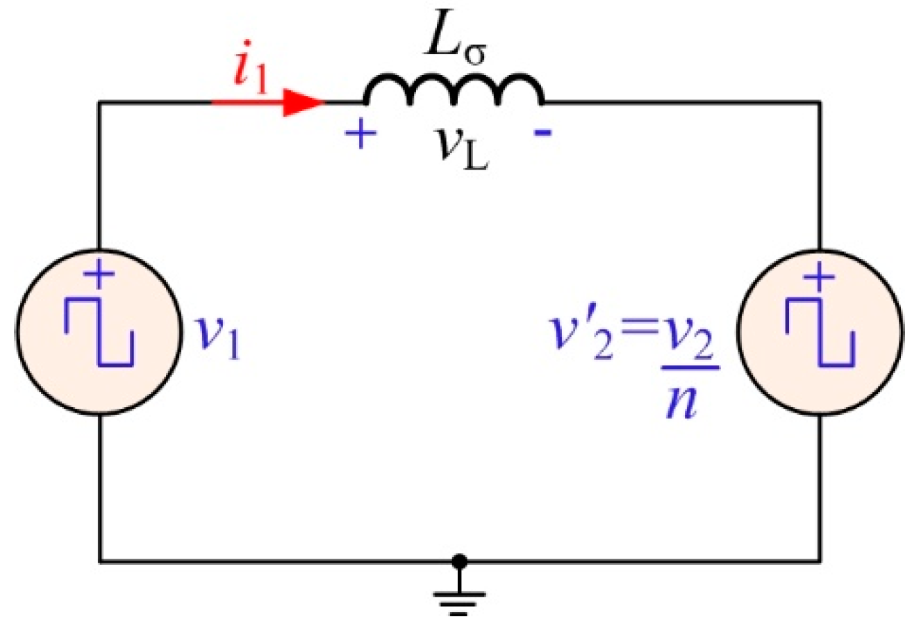
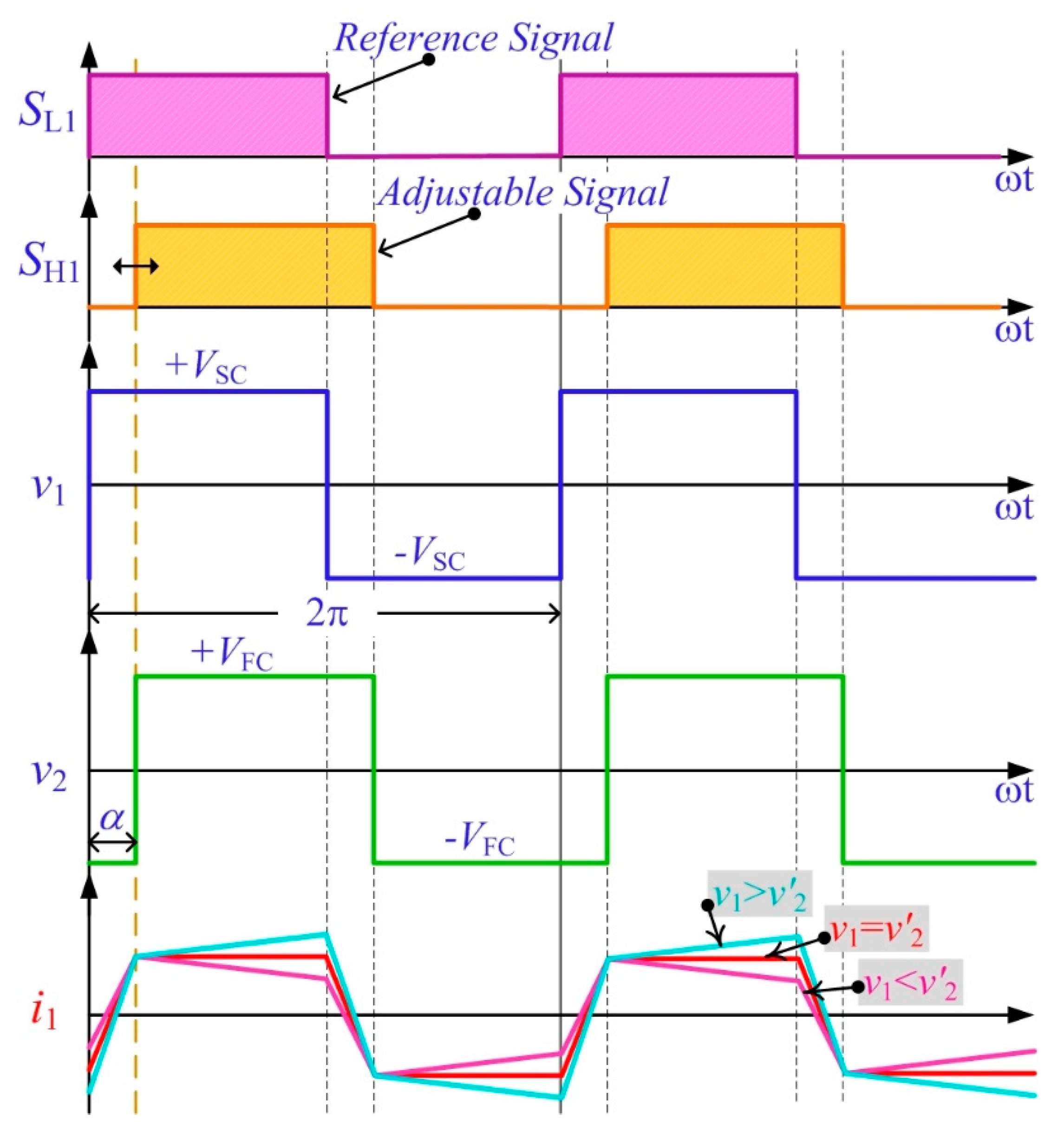
2.2. Proposed Two-Port Bidirectional DC-DC Converter

The proposed two-port bidirectional DC-DC converter (or dual-active bridge (DAB) converter) for SC applications is displayed in Figure 7. This DC-DC converter topology has been investigated by De Doncker et al. [34] and Kheraluwala et al. [35]. In this topology, two bridges converters are employed and interfaced with a high-frequency transformer. The regulation is based on a phase-shift algorithm. Each bridge converter (SC and DC bus sides) produces a square-wave voltage, which is applied either to the primary or secondary of the transformer. The two square-wave voltages (v1 and v2) are phase-shifted between each other. This phase-shift α is a relevant variable, since it rules the direction and the quantity of power flowing between the SCs and DC bus or main power source. If both squares-wave sources were substituted by their main components [36,37], a simplified electrical scheme could be retrieved, as shown in Figure 8. Through the tuning of the phase-shift, an operation at fixed frequency with full control over the power transfer is made possible. The power flowing through the inductor Lσ represents the combination of the primary-referred transformer leakage inductance and the possible external bulk inductors. This circuit makes possible a fixed-frequency operation and the use of the total leakage inductance of the transformer as the main energy transfer component.
For the power transfer between the low voltage side (LVS) and high voltage side (HVS), the converter operates in step-up mode to discharge the SCs, whereas for the inverse power transfer, the converter operates in step-down mode to charge the SCs from the DC bus or absorb the energy during a regenerative braking operation. At the LVS, MOSFETS are generally used, while at the HVS IGBTs are more suitable to withstand high voltage stress.
Given that the converter operations have been presented in detail by Jain et al. [38] and Bai et al. [39], here we only emphasize the circuit operations relevant for the development of the reduced-order model. Figure 9 presents the switching waveforms of the converter during switching periods at α > 0 (either during boost mode or discharging the storage device). The average transferred power can be retrieved by evaluating the average power at the transformer terminals, i.e.
p SC = 1 2 π 0 2 π ( v 1 i 1 ) d ( ω t ) .
In an ideal lossless circuit [40,41], the power flow in the system is assessed by:
p SC = v SC v FC 2 π f S L σ n α ( 1 | α | π ) ,
where α is the phase-shift (in radians), Lσ is the total transformer leakage inductance (in addition to any series inductances in (H)), n is the transformer turns ratio (=N2/N1), and fS is the switching frequency in (Hz). In the case where power is transferred from LVS to HVS, the voltage v2 is obtained from v1 through the transformer and the phase-shift α is positive, as shown in Figure 9. By comparison, in the opposite way, the voltage v1 is obtained from v2 and the phase-shift is negative in this case. The operation change of the phase-shift can be easily realized through a fit timing control of the power electronics devices. It has to be noted that Lσ is an important component since it allows obtaining the maximum quantity of power which could be transferred at a given switching frequency. As a result, a high-power density converter can be obtained, including a low leakage transformer. Based on expression (2), it can be seen that the maximum power flow is reached at α = π/2. Therefore, the usual phase-shift has to be included between −π/2 ≤ α ≤ π/2.

2.3. Reduced-Order Model of the System

Based on Figure 7, a reduced-order model of the system is obtained, including the PEMFC model, SC model, and converter, and the load is connected to the DC bus, as shown in Figure 10. In this part, only the static losses in the converter have been taken into consideration (called reduced-order model), and the rSC is useful in describing the global resistance of the equivalent series resistance (ESR) in an SC module, the parasitic resistance of the inductor, the transformer resistance, and the on-state resistance of power switches.
Considering the SC power pSC is equal to its desired value pSCd, the following expression can be given:
p SCd = p SC = v SC i SC .
The stored energy EB in the DC bus is expressed as follows:
E B = 1 2 C B v FC 2 .
The derivative of the stored energy EB, according to pFC, pSCo, and pCH, is provided by this differential expression:
E ˙ B = p FC + p SCo p CH ,
where
p SCo = p SC r SC ( p SC v SC ) 2 ,
and
p CH = v FC i CH = 2 E B C B i CH .

3. Control Algorithm and Control Law

The energy storage system can assist FC main source operations to reduce electrical solicitations. Given that the dynamics of the FC are slow, dynamic operations can be ensured by SC due to their fast response time to dynamics. Hence, the use of SCs is required to respond to dynamic solicitations, whereas the FC is employed to supply steady-state conditions, enabling optimizing its life span. The developed power management strategy aims at sharing the requested power (i.e., static and dynamic) between the FC and the SC to keep the SOC of the SCs in a specific range in order to optimize the energy efficiency of the system and decrease the hydrogen consumption of the FC (related to Figure 6) [42]. Then, SCs were used to assist an FC main power source, in which the SC was used as the high dynamic storage device that provided the fast dynamic power supply and micro cycles.
As earlier mentioned in Section 2, two voltage variables related to the FC and SC must be regulated:
(1)
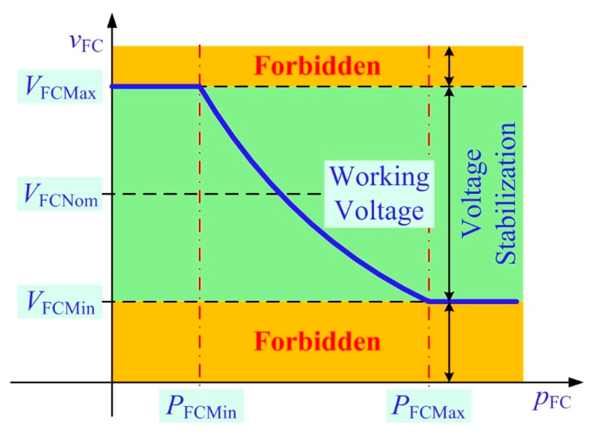
The FC voltage vFC is a relevant variable.
(2)
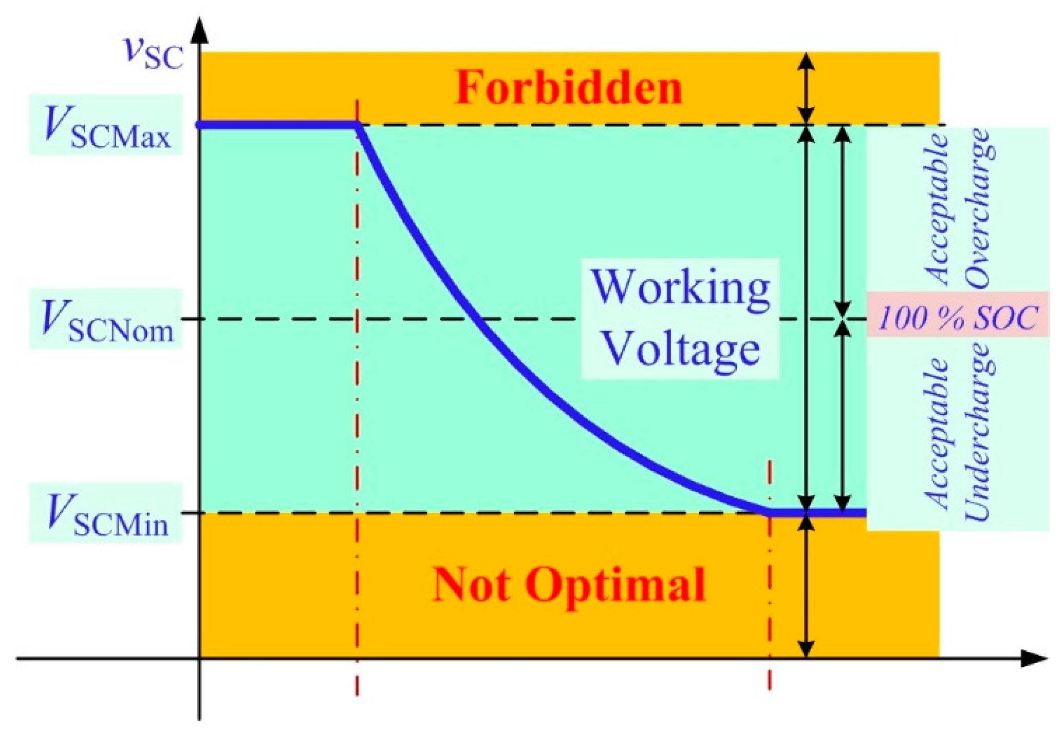
The SC voltage vSC is the second most essential.
For that reason, SC operates to supply power to the DC bus. As displayed in Figure 4 and Figure 6, this means the FC voltage (or the DC bus voltage, here) is regulated over the interval (VFCMin, VFCMax), and the FC enables providing energy to increase the SOC of the SC.

3.1. Development of Flatness Control Applied to the Supercapacitor Energy Storage

To stabilize the FC voltage vFC (related to the DC bus voltage, vBus) from the flatness control theory (Appendix A), the control input variable u, flat output y, and state variable x are defined as:
y = E B ,
u = p SCd ,
x = v FC .
Here, pSCd is the desired SC power (refer to (2)) and we assume that pSCd = pSC.
Proof. 
Based on (4) and (A4), the state variable x is expressed as follows:
x = 2 y C Bus = f x ( y ) .
 □
Using (5), (7), and (A5), the control variable u (=pSCd) is assessed based on the flat output y and its time derivatives and expressed as:
u = 2 p SCLim [ 1 1 ( y ˙ + 2 y C B i Load p FC p SCLim ) ] = f u ( y , y ˙ ) = p SCd ,
where
p SCLim = v SC 2 4 r SC .
Here, pSCLim is the restricted maximum power of the SC converter. In both equations, x = f x ( y ) and u = f u ( y , y ˙ ) correspond with (A4) and (A5), and therefore the developed reduced-order model can be considered as a flat system.

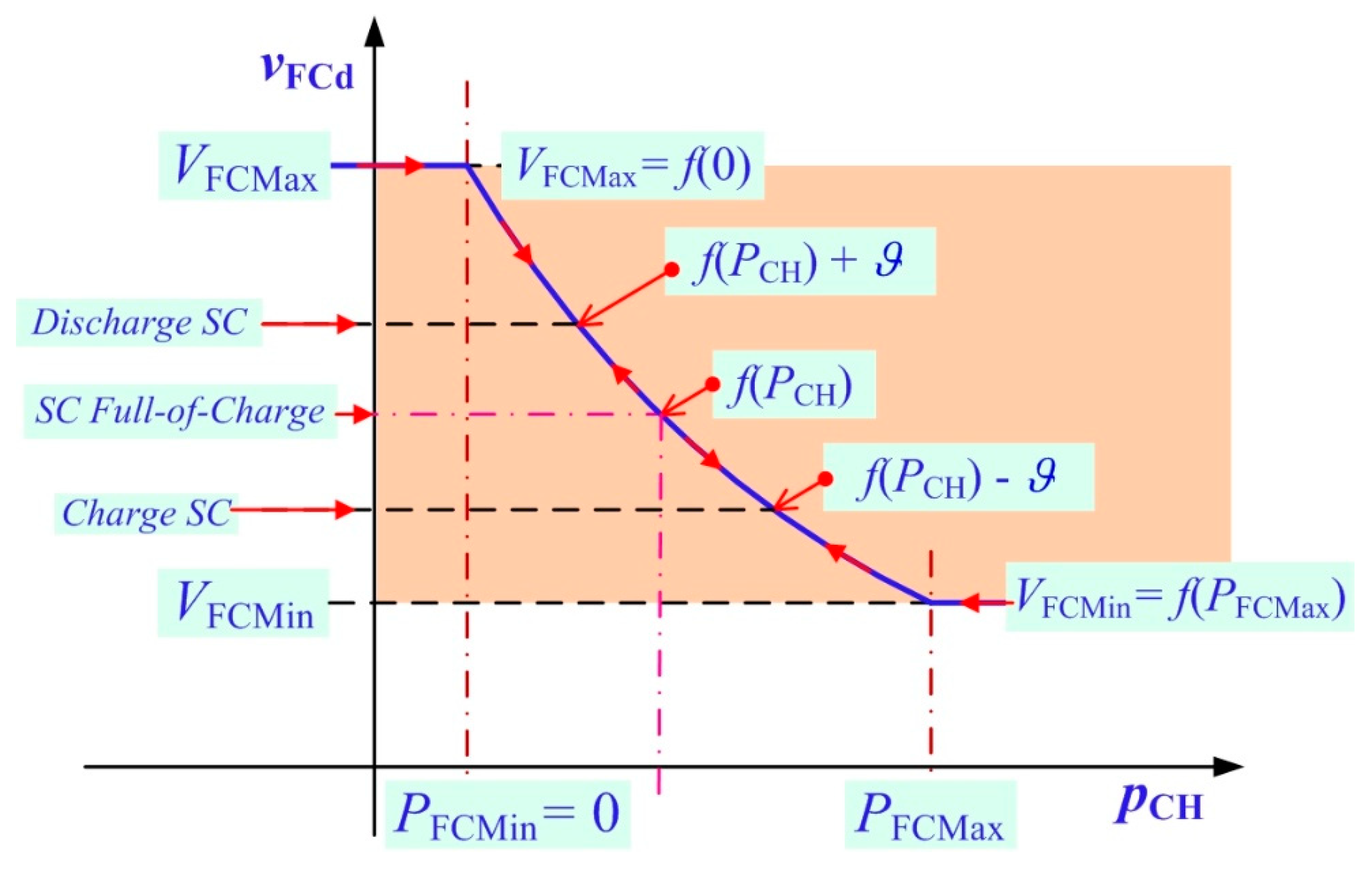
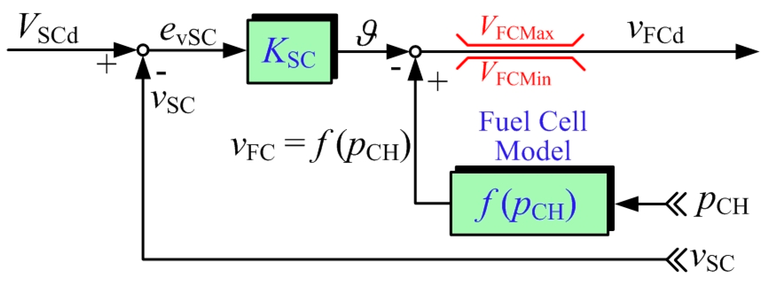
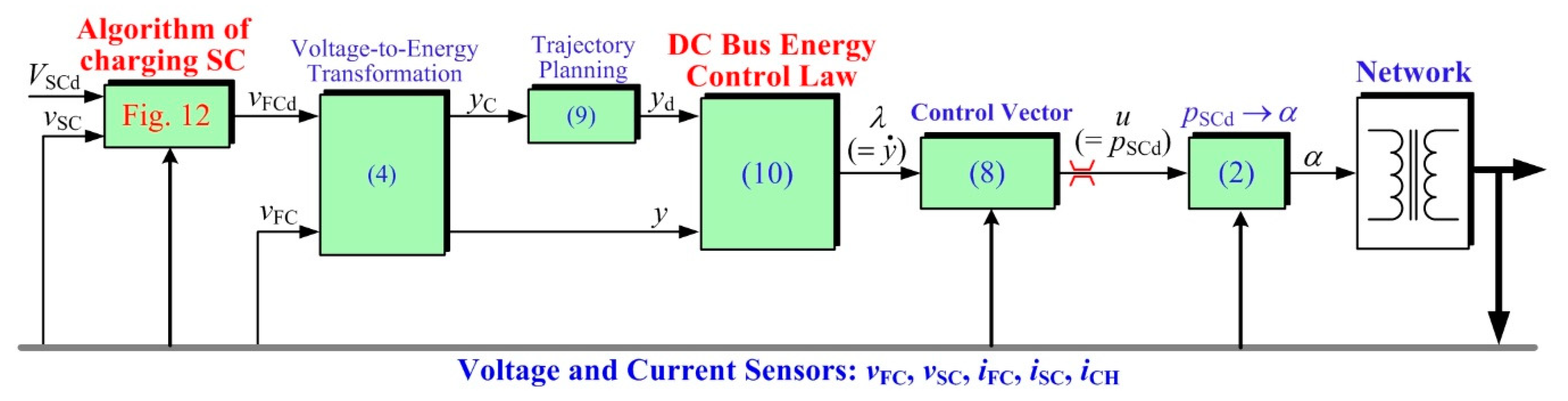
3.2. Production of the FC Voltage Set Point and Charging Supercapacitor Strategy

The desired DC bus energy EBd (=yd) changes according to the different operating conditions of the system. This set point is tuned so that it confirms that both dynamics (i.e., EB and vFC) fluctuate slowly. Hence, the FC is protected against dynamic solicitations. Besides this, the stored energy variable EB of the DC bus has to be set to the maximum power that the FC can provide. As a result, the FC voltage must be included within a specific interval (VFCMin = f(PFCMax), VFCMax = f(PFCMin) = 0)), where PFCMax is the maximum (i.e., rated) FC power and f(pFC) is the VFCPCH characteristic function of FC, which should be a known function; see Figure 11.
At the equilibrium point, the power generated by the FC has to meet the load power pCH and, as presented in Section 2, the SCs have to be fully charged (i.e., vSC = VSCNom). For that reason, a particular function that produces the desired FC voltage vFCd and increases the SOC of the SC is given as depicted in Figure 11 and Figure 12, where KSC is the positive gain of the control parameter. If VSCd >> vSC (evSC >> 0) and ϑ >> 0, vFCd is saturated at a constant minimum level VFCMin (see Figure 11), which leads to a quick SC charging. Once vSCVSCd (evSC ≈ 0) and ϑ is a small positive value, vFCd increases linearly to the operating point (vFC = f(PCH)). In the opposite condition, if VSCd << vSC (evSC << 0) and ϑ << 0, the vFCd is saturated at a constant maximum level VFCMax, which leads to a quick SC discharging. Once vSCVSCd (evSC ≈ 0) and ϑ becomes a small negative value, the vFCREF decreases linearly to the operating point (vFCd = f(PCH)).

3.3. FC Voltage Balance and Control Law

The desired FC voltage vFCd (refer to Figure 12) is changed to the flat output command yC by (4). According to (A12), a standard second-order filter is employed to set the FC power dynamics. Therefore, the desiderate flat output trajectory is expressed as:
y d ( s ) y C ( s ) = ω n 2 2 s 2 + 2 ζ 2 ω n 2 s + ω n 2 2 ,
where ωn2 and ζ2 are the control parameters; see Appendix A.
According to (A7), a feedback control algorithm that ensures exponential asymptotic pursue of the trajectory is provided below:
λ = y ˙ = y ˙ REF + ( 2 ζ 1 ω n 1 ) ( y d y ) + ( ω n 1 2 ) 0 t ( y d y ) d τ ,
where ωn1 and ζ1 are the control parameters; see Appendix A.
Finally, Figure 13 displays the developed control strategy of the SC energy storage substation for vehicle applications. The production of the desiderate FC voltage leads to vFCd, which is after that calculated for yC and yields yd for the DC bus energy balance. The DC bus energy control strategy and control vector produces a desiderate SC power pSCd (= u, related to (8) and (10)) and, finally, this signal transforms to a desired phase-shift α for a DAB converter.
Proof Stability. 
The association between the switching frequency fS of the DAB converter and the above-mentioned natural frequency ωn is roughly particular based on the cascade control structure [31]. According to the well-known Nyquist theorem, the desiderate natural frequency can be expressed as follows:
ω n 2 < < ω n 1 < < 2 π f S ( = ω S ) .
 □
According to the Symmetrical Optimum Method, the desired damping coefficient ζ can be expressed as follows:
ζ 1 = 1 2 | Control Law ,   ζ 2 = 1 | Trajectory Planing .

4. Performance Validation

The overviews of the real-time control implementation and the experimental test rig realized at the GREEN laboratory, Université de Lorraine are displayed in Figure 14 and Figure 15, respectively. The developed control strategy (Figure 13) was carried out in MATLAB/Simulink environment and then implemented into the dSPACE DS1103 controller platform. The sampling time has been chosen equal to 40 µs to make possible the operation mode (i.e., SC charging or discharging) of the phase-shift α of the DAB converter.
Measurements of the FC voltage vFC and SC voltage vSC were performed utilizing LEM LV-25P sensors (zero-flux Hall effect sensors). Measurements of the load current iCH, FC current iFC, and SC current iSC were carried out utilizing the LEM LA-55P sensors (zero-flux Hall effect sensors).
The specifications of the control parameters are summarized in Table 1. To avoid damaging the FC during experiments, the PEMFC was replaced by an FC emulator of 420 W (PFCMax) at VFCMin = 80 V. The SC bank (CSC: 250 F; maximum voltage VSCMax: 32 V) is composed of two SC modules, BMOD0500-P016 (by Maxwell Technologies Inc.: 500 F, 16 V, 500 A) series-connected. Related to Figure 7, the DAB converter (1 kW) was designed and realized in the laboratory. The specifications of the converter are Lσ = 2.8 µH, n = 5, and the constant switching frequency fS = 20 kHz. The dSPACE DS1103 controller platform enables generating the phase-shift α (based on Figure 13), but an external field-programmable gate array (FPGA) board is required to create the gating control signals of the DAB converter, as shown in Figure 14. In previous works [42], dSPACE controller boards are generally used to control classic buck-boost and two-phase interleaved buck-boost converters, but they are not suitable to control DAB or interleaved buck-boost converters (e.g., from three phases) due to their limited sampling time. For this reason, the use of a FPGA board to control a DAB converter represents a contribution compared to the previous works reported for this research topic.
Finally, an electronic load was connected to the DC bus voltage of 100 V, which operated as a two-quadrant converter, enabling the system to emulate vehicle operating modes such as motoring, ride-through, and braking. As highlighted in the introduction section, the chosen DC bus voltage is around 100 V and is lower compared to the usual DC bus voltages for transportation applications [8]. This choice was guided by the fact that the PEMFC emulator is directly connected to the DC bus without using a step-up DC-DC boost converter. PEMFC stacks suffer from generating a low DC voltage, since their number of cells must be limited to guarantee a certain reliability in case of failures. The PEMFC voltage range is included between 80 and 100 V to protect the PEMFC in case of degradations and to exploit a large power from the PEMFC. For this reason, the DAB converter interfaces with the SC module and the DC bus includes a transformer, which has a turns ratio that has been chosen as 5 to meet the required DC voltage. To increase the DC bus voltage, a step-up DC-DC converter between the PEMFC and the DC bus voltage is required. However, it increases the cost of the system and the complexity of the control, since an additional converter must be controlled to ensure the stability of the DC bus. Currently, the use of classic step-up or interleaved boost converter does not enable obtaining a high DC voltage due to their limited ratio. For this reason, the DC-DC converter at a high voltage ratio must be employed to get high DC bus voltage levels [2]. In this work, only the DAB converter and the stored energy in the DC bus are managed to ensure the stability of the system and performance as well.
Figure 16 depicts the switching waveforms in the steady-state operation of the desired SC power of +150 W and displays the switching characteristics of the DAB converter. This screen demonstrates the gate drive signal (see Figure 7) for SL1 and vGS_SL1 (Ch1), the gate drive signal for SH1 and vGS_SH1 (Ch2), the primary LVS transformer current i1 (Ch3), and the SC current iSC (Ch4). A phase-shift α equal to +10 degrees and iSC = +7 A can be seen. This test presents the SC unit in discharging state, and the SC in the LVS generates a power of 150 W to the DC bus in the HVS.
To present FC voltage regulation in an interval (VFCMin = f(PFCMax), VFCMax = f(PFCMin = 0)) by using the proposed control algorithm during driving cycles, the experimental data measured during the motoring mode are illustrated in Figure 17. The graphs show the FC voltage, desired DC bus energy, load power pCH, SC power pSC, FC power, SC current iSC, and SC voltage vSC (or the SC SOC). In the beginning, pCH = 200 W, which simulates a running vehicle. It has to be noted that this power is smaller than the limited FC power PFCMax of 420 W. The SOC of SCs is 100%, i.e., vSC = VSCREF = 22 V; consequently, the FC main source provides power to the load (pFC = pCH), pSC = 0 W, yREF = 19.8 J, and vBus = 92 V. Then, at t = 20 s the load power increased to its constant power level of 390 W, which emulates vehicle acceleration. As can be observed, this power is still smaller than the limited FC power PFCMax of 420 W. The following observations are made:
(1)
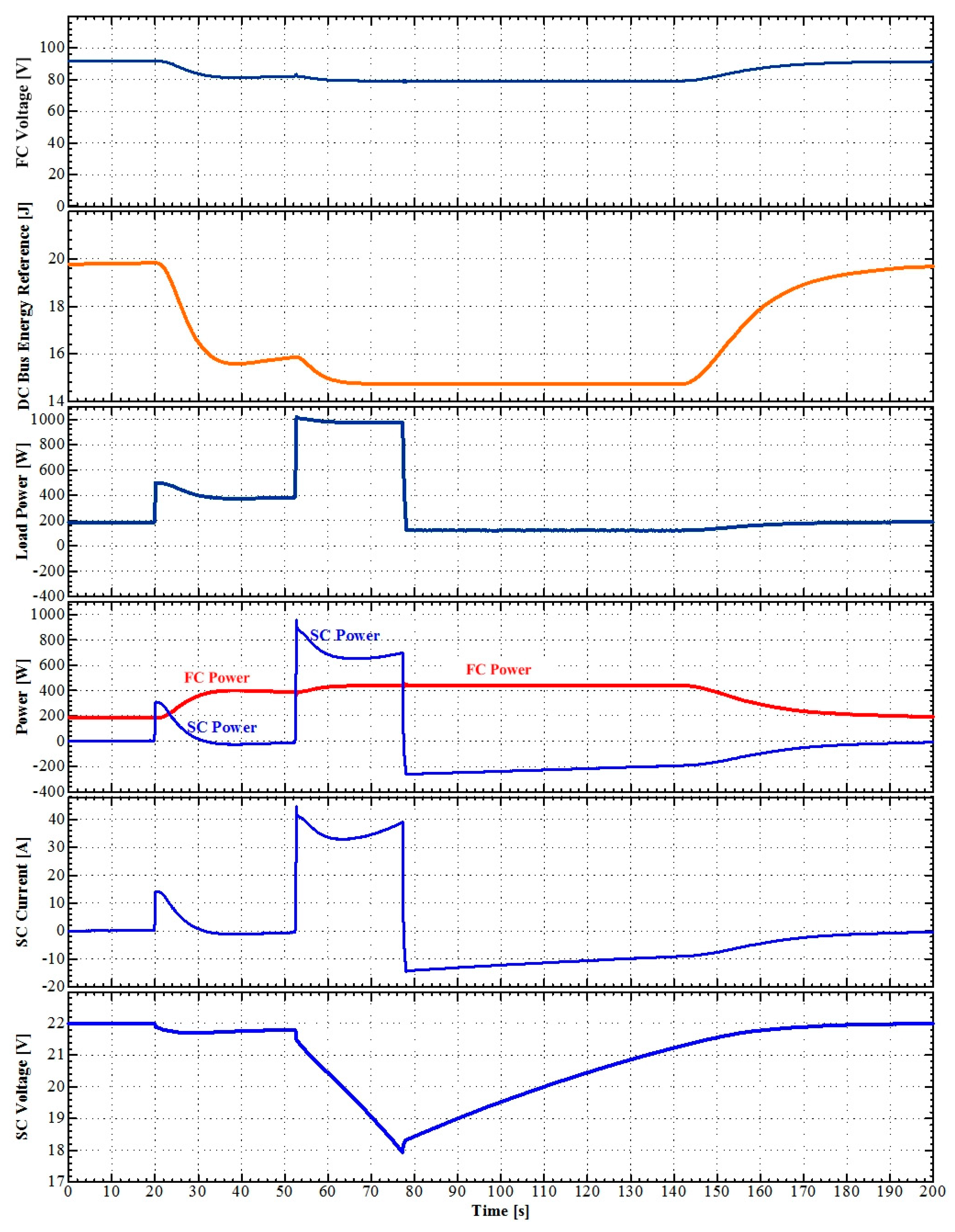
The trajectory planning (9) generated a desired DC bus energy trajectory yd from 19.8 J to 15.8 J.
(2)
In effect, the FC voltage follows the reference trajectory yd.
(3)
The SC provided a major part of the power requested during the load step and went back to charge the SC storage device, given that VSCd (= VSCNom) > vSC.
(4)
Accordingly, the FC power increased, with a limited slope, to a final power of 400 W to meet the load requests and charge the SC storage device.
Next, at t = 52 s, the load power increased quickly from 390 W to 1 kW (>PFCMax = 420 W). This phenomenon emulates the synchronized acceleration of several vehicles and represents the motoring: ride-through mode. The following explanations can be provided:
(1)
The trajectory planning (9) created a desiderate trajectory yd from 15.8 J to 15 J, which corresponds to the limited minimum FC voltage VFCMin of 80 V.
(2)
The SC unit, which provides the most important part of the power requested during each load step, remained in a discharged state as the result of the load step, since the steady-state load power (1 kW) is higher than the limited maximum power of the FC generator.
(3)
Concurrently, the FC power rises up by limiting its slope to its set maximum power of 420 W.
Then, at t = 78.8 s, the load power stepped from 1 kW to 200 W (<PFCMax) and VSCd (= 22 V) > vSC (=18 V). Thus, the operating mode of the SC changes from discharging to charging and illustrates the following three states:
(1)
The FC source keeps providing a set maximum power of 420 W to respond to the load requests and charge the SC.
(2)
At t = 140.4 s, the SC is close to being fully charged—i.e., vSC = 21.5 V. Accordingly, the FC power is decreased with set power dynamics, corresponding to the energy reference trajectory yd.
(3)
Finally, at t = 190 s the SOC of SC reached 100%—i.e., vSC = vSCd = 22 V. After slowly decreasing, pSC = 0 W and pFC = pLoad.
The experimental data measured during the braking mode are demonstrated in Figure 18. At the beginning, pCH = 200 W (<PFCMax = 420 W). The SOC of SC is 100%—i.e., vSC = VSCd = 22 V; consequently, the FC generator supplies power to the load (pFC = pCH), pSC = 0 W, yd = 19.8 J, and vFC = 92 V. At t = 20 s, the load power increases to its final power level of −300 W, which emulates vehicle braking. This power of −300 W is smaller than the set minimum FC power of 0 W. Therefore, the desiderate energy trajectory increases to the limited value of 23.5 J, corresponding to a VFCMax of 100 V. The SC changes from an idle state to deeply charging and details the following two states:
(1)
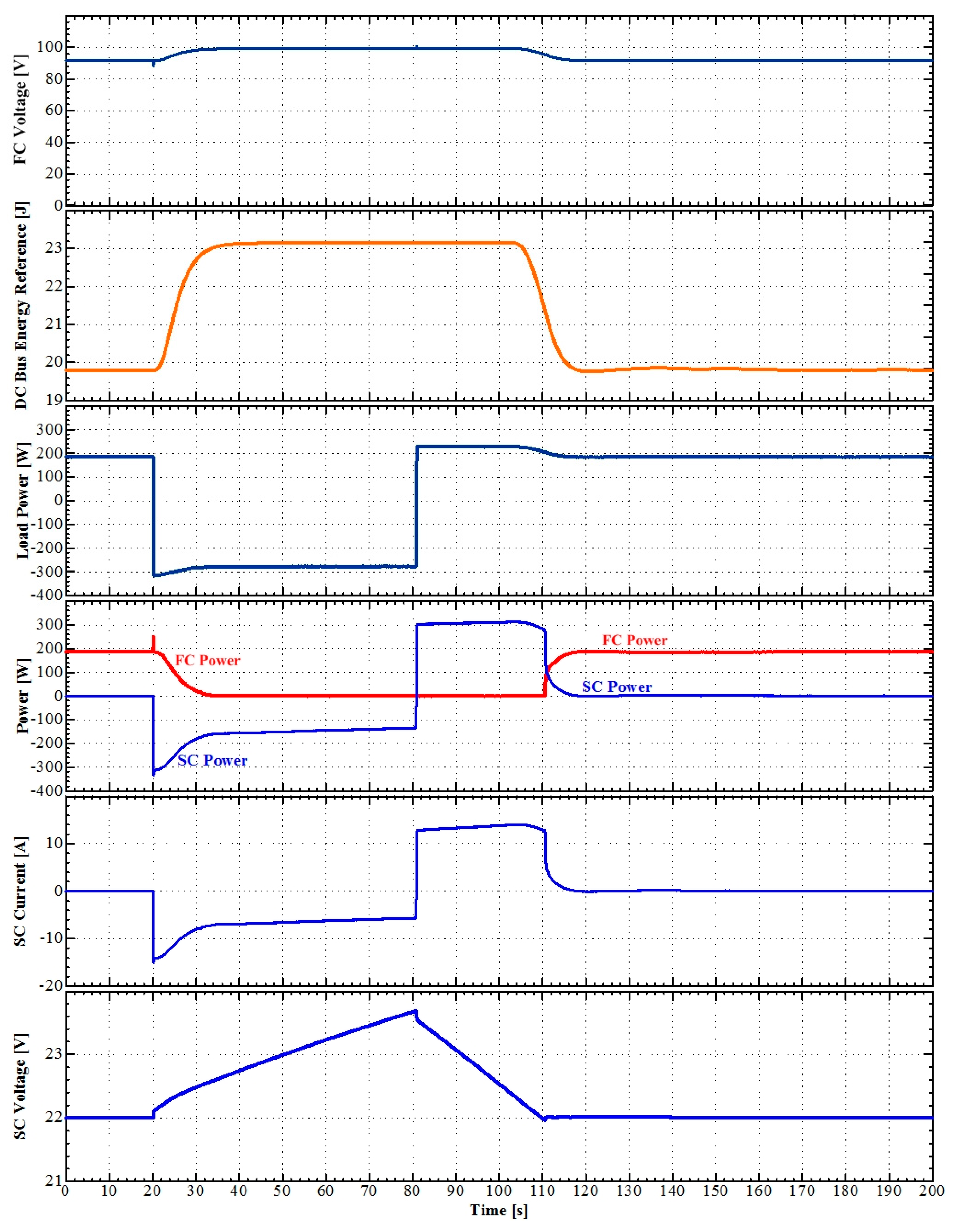
Because the desired energy trajectory was too slow to limit the electrical stress of the FC source, the SC unit was charged by the FC and load.
(2)
At t = 35 s, the FC power decreased to zero; after that, the SC unit was charged only by regenerative braking. The FC voltage is always limited at 100 V. The SC was overloaded (VSCNom < vSC); nonetheless, the SC voltage was within the acceptable level (vSC < VSCMax). Refer to Figure 5.
Afterward, at t = 80 s and VSCd (=22 V) < vSC (=23.5 V), the load power varies from −300 W to 200 W. Consequently, the SC changes from charging to discharging and illustrates the following two states:
(1)
The SC unit supplied the over-energy, stored from the last braking, to drive the load.
(2)
At t = 110 s, after discharging the SC module was fully charged (VSCd = vSC) and the FC supplied the energy to drive the load; pFC = pCH and pSC = 0.
Based on the obtained results in Figure 17 and Figure 18, the proposed control algorithm demonstrates the stability of the system and the suitable response in FC voltage control to the desiderate set point between the set minimum and maximum levels. The power balance between the load and the sources (i.e., FC and SC) (pCH = pFC + pSC) is always ensured, which is of key significance when utilizing a SC module to enhance the dynamic performance of the global distribution system, employing a control based on differential flatness-based control.

5. Conclusions

This article introduced a control strategy to accomplish fuel cell voltage stabilization utilizing supercapacitors as the secondary source for transportation applications. A dual-active bridge converter was chosen as a two-quadrant supercapacitor converter (ground isolation). Compared to previous works, the main contributions of this work are the developed energy management strategy, aiming at regulating the fuel cell and supercapacitor voltages in an SC-based energy storage substation in mobility applications, and confirming the dynamic performance of the differential flatness-based control of an FC voltage balance. This article deals with the original use of supercapacitors, and the developed control algorithm consists of generating a simple control strategy. Through this control algorithm, the fuel cell can be protected against dynamic solicitations from the load. In this case, the supercapacitors provide the major part of the power requested by the load, and they can be charged during regenerative braking operating modes. The fuel cell and supercapacitor voltages are always kept in a specific voltage range to enhance their performance. To validate the developed energy management strategy, a small-scale experimental test rig was realized in the laboratory; it includes an FC emulator (100 V, 420 W) and an SC module (250 F, 32 V, Maxwell Technologies). The obtained experimental results with the experimental test rig (DC bus voltage: 100 V, 1 kW) demonstrated the effectiveness of the closed-loop control of the system to respond to static and dynamic operations based on the different operating modes, such as motoring, ride-through, and braking, generally met in mobility applications.

Author Contributions

Conceptualization, S.P. and B.N.-M.; methodology, P.K. and D.G.; validation, M.P. and D.G.; formal analysis, N.B.; writing—original draft preparation, P.T.; writing—review and editing, D.G.; visualization, P.K.; investigation, B.N.-M.; supervision, N.T. All authors have read and agreed to the published version of the manuscript.

Funding

This work was supported by the research program cooperation of the “International Research Partnerships: Electrical Engineering Thai-French Research Center (EE-TFRC)” between Université de Lorraine and King Mongkut’s University of Technology North Bangkok and under Grant No. KMUTNB-61-GOV-D-68.

Conflicts of Interest

The authors declare no conflict of interest.

Appendix A. Principle of Nonlinear Control Based on the Differential Flatness

Differential flatness theory was first introduced by Fliess et al. [24], considering the following nonlinear system:
x ˙ = f 1 ( x , u ) , x n , u m ,
y = f 2 ( x , u ) , y m ,
where y is output vector (here, named the flat outputs), x is the state vector, and u is input or control vector.
Mathematically, a nonlinear network can be defined as a flat system when the following two essential constraints are fulfilled.
(1) The flat outputs y can be written according to control input variables u, state variables x and a finite number of input’s derivatives:
y = f y ( x , u , u ˙ , u ¨ , u ( α ) ) .
(2) The state variables x and control input variables u can be written according to the flat outputs y and a finite number of its derivatives as:
x = f x ( y , y ˙ , y ¨ y ( β ) ) ,
u = f u ( y , y ˙ , y ¨ y ( γ ) ) ,
where α, β, and γ are positive integers depending on the order of the model and y(r) is the rth derivative with respect to time. The flat output variables y are equal in number to the control input variables u.
If the output variables of interest can be proven to be flat outputs y, the desired output signal yd becomes straightforward. For example, for the 1st order system the dynamics of the resulting linear error dynamics can be specified by introducing a new stabilizing input λ (control law, refer to Figure A1) [43,44,45].
0 = ( y ¨ y ¨ d ) + K p ( y ˙ y ˙ d ) + K i ( y y d ) .
Then,
λ = y ˙ = y ˙ d + K p ( y d y ) + K i ( y d y ) d τ ,
where Kp and Ki are the set of controller parameters and replace the first derivative of y in the term of the control input with λ according to (A7). This results in the following control vector:
u = f u ( y , λ ) ,
where the control inputs are calculated depending on the measured outputs y and desired outputs yd. The set of controller parameters Kp and Ki are chosen such that the roots of the second-order standard equation in the complex variable s:
y ( s ) y d ( s ) = ω n 0 2 s 2 + 2 ζ 0 ω n 0 s + ω n 0 2 .
Obviously, the tracking error e = y y d satisfies:
e ¨ + K p e ˙ + K i e = s 2 + 2 ζ 0 ω n 0 s + ω n 0 2 ,
K p = 2 ζ 0 ω n 0 , K i = ω n 0 2 ,
where, ζ0 and ωn0 are the desired dominant damping ratio and natural frequency that specify properties such as response time, overshoot, and bandwidth.
Finally, the trajectory of yd is defined to meet the following requirements: time response of the flat output y and limiting the peak power during the startup. Hence, the trajectory response of yd is planned to be a second-order type by using a standard second-order filter as follows:
y d ( s ) y C ( s ) = ω nT 2 s 2 + 2 ζ T ω nT s + ω nT 2 ,
where yC is the command signal and ζ1 and ωn1 are the desired dominant damping ratio and natural frequency.
Figure A1. Concept of the differential flatness based control approach of the 1st order system.
Energies 13 02794 g0a1

References

  1. Felseghi, R.-A.; Carcadea, E.; Raboaca, M.S.; TRUFIN, C.N.; Filote, C. Hydrogen Fuel Cell Technology for the Sustainable Future of Stationary Applications. Energies 2019, 12, 4593. [Google Scholar] [CrossRef] [Green Version]
  2. Guilbert, D.; N’Diaye, A.; Gaillard, A.; Djerdir, A. Reliability improvement of a floating interleaved DC/DC boost converter in a PV/fuel cell stand-alone power supply. EPE J. 2019, 29, 49–63. [Google Scholar] [CrossRef]
  3. Bizon, N.; Mazare, A.G.; Ionescu, L.M.; Thounthong, P.; Kurt, E.; Oproescu, M.; Serban, G.; Lita, I. Better Fuel Economy by Optimizing Airflow of the Fuel Cell Hybrid Power Systems Using Fuel Flow-Based Load-Following Control. Energies 2019, 12, 2792. [Google Scholar] [CrossRef] [Green Version]
  4. Hegazy, O.; Van Mierlo, J.; Lataire, P.; Coosemans, T.; Smenkens, J.; Monem, M.A.; Omar, N.; Van den Bossche, P. An Evaluation Study of Current and Future Fuel Cell Hybrid Electric Vehicles Powertrains. World Electr. Veh. J. 2013, 6, 476–483. [Google Scholar] [CrossRef] [Green Version]
  5. Bizon, N.; Lopez-Guede, J.M.; Kurt, E.; Thounthong, P.; Mazare, A.G.; Ionescu, L.M.; Iana, G. Hydrogen economy of the fuel cell hybrid power system optimized by air flow control to mitigate the effect of the uncertainty about available renewable power and load dynamics. Energy Convers. Manag. 2019, 179, 152–165. [Google Scholar] [CrossRef]
  6. Serpi, A.; Porru, M. Modelling and Design of Real-Time Energy Management Systems for Fuel Cell/Battery Electric Vehicles. Energies 2019, 12, 4260. [Google Scholar] [CrossRef] [Green Version]
  7. Sharer, P.; Rousseau, A. Benefits of Fuel Cell Range Extender for Medium-Duty Vehicle Applications. World Electr. Veh. J. 2013, 6, 452–463. [Google Scholar] [CrossRef] [Green Version]
  8. Lü, X.; Qu, Y.; Wang, Y.; Qin, C.; Liu, G. A comprehensive review on hybrid power system for PEMFC-HEV: Issues and strategies. Energy Convers. Manag. 2018, 171, 1273–1291. [Google Scholar] [CrossRef]
  9. Yao, G.; Du, C.; Ge, Q.; Jiang, H.; Wang, Y.; Ait-Ahmed, M.; Moreau, L. Traffic-Condition-Prediction-Based HMA-FIS Energy-Management Strategy for Fuel-Cell Electric Vehicles. Energies 2019, 12, 4426. [Google Scholar] [CrossRef] [Green Version]
  10. Sikkabut, S.; Mungporn, P.; Ekkaravarodome, C.; Bizon, N.; Tricoli, P.; Nahid-Mobarakeh, B.; Pierfederici, S.; Davat, B.; Thounthong, P. Control of high-energy high-power densities storage devices by li-ion battery and supercapacitor for fuel cell/photovoltaic hybrid power plant for autonomous system applications. IEEE Trans. Ind. Appl. 2016, 52, 4395–4407. [Google Scholar] [CrossRef] [Green Version]
  11. Do, T.C.; Truong, H.V.A.; Dao, H.V.; Ho, C.M.; To, X.D.; Dang, T.D.; Ahn, K.K. Energy Management Strategy of a PEM Fuel Cell Excavator with a Supercapacitor/Battery Hybrid Power Source. Energies 2019, 12, 4362. [Google Scholar] [CrossRef] [Green Version]
  12. Kasicheyanula, S.; John, V. Adaptive Control Strategy for Ultracapacitor Based Bidirectional DC–DC Converters. IEEE Trans. Ind. Appl. 2019, 55, 1717–1728. [Google Scholar] [CrossRef]
  13. Dey, S.; Mohon, S.; Ayalew, B.; Arunachalam, H.; Onori, S. A Novel Model-Based Estimation Scheme for Battery-Double-Layer Capacitor Hybrid Energy Storage Systems. IEEE Trans. Control Syst. Technol. 2019, 27, 689–702. [Google Scholar] [CrossRef]
  14. Mamun, A.; Liu, Z.; Rizzo, D.M.; Onori, S. An Integrated Design and Control Optimization Framework for Hybrid Military Vehicle Using Lithium-Ion Battery and Supercapacitor as Energy Storage Devices. IEEE Trans. Transp. Electrif. 2019, 5, 239–251. [Google Scholar] [CrossRef]
  15. Maher, B. Ultracapacitors Provide Cost and Energy Savings for Public Transportation Applications. Battery Power Mag. 2006, 10, 6. [Google Scholar]
  16. Godbersen, C. Energy storage system based on double layer capacitor technology—The gateway to high efficient improvement of mass transit power supply. In Proceedings of the 2nd UIC Railway Energy Efficiency Conference, Paris, France, 4–5 February 2004. [Google Scholar]
  17. Steiner, M.; Scholten, J. Energy Storage on board of railway vehicles. In Proceedings of the 11th European Conference on Power Electronics and Applications (EPE), Dresden, Germany, 11–14 September 2005. [Google Scholar]
  18. Kawashima, K.; Uchida, T.; Hori, Y. Development of a Novel Ultracapacitor Electric Vehicle and Methods to Cope with Voltage Variation. In Proceedings of the 5th IEEE Vehicle Power and Propulsion Conference (VPPC’09), Dearborn, MI, USA, 7–11 September 2009. [Google Scholar]
  19. Chakraborty, S.; Vu, H.-N.; Hasan, M.M.; Tran, D.-D.; Baghdadi, M.E.; Hegazy, O. DC-DC Converter Topologies for Electric Vehicles, Plug-in Hybrid Electric Vehicles and Fast Charging Stations: State of the Art and Future Trends. Energies 2019, 12, 1569. [Google Scholar] [CrossRef] [Green Version]
  20. Ibanez, F.M.; Beizama Florez, A.M.; Gutiérrez, S.; Echeverrría, J.M. Extending the Autonomy of a Battery for Electric Motorcycles. IEEE Trans. Veh. Technol. 2019, 68, 3294–3305. [Google Scholar] [CrossRef]
  21. Thammasiriroj, W.; Chunkag, V.; Phattanasak, M.; Pierfederici, S.; Davat, B.; Thounthong, P. Nonlinear model based single-loop control of interleaved converters for a hybrid source system. ECTI Trans. Electr. Eng. Electron. Commun. 2017, 15, 19–31. [Google Scholar]
  22. Shah, S.S.; Bhattacharya, S. A Simple Unified Model for Generic Operation of Dual Active Bridge Converter. IEEE Trans. Ind. Electron. 2019, 66, 3486–3495. [Google Scholar] [CrossRef]
  23. Guo, Z.; Sha, D. Dual-Active-Bridge Converter with Parallel-Connected Full Bridges in Low-Voltage Side for ZVS by Using Auxiliary Coupling Inductor. IEEE Trans. Ind. Electron. 2019, 66, 6856–6866. [Google Scholar] [CrossRef]
  24. Fliess, M.; Lévine, J.; Martin, P.; Rouchon, P. Flatness and defect of nonlinear systems: Introductory theory and examples. Int. J. Control 1995, 61, 1327–1361. [Google Scholar] [CrossRef] [Green Version]
  25. Ogunbodede, O.; Nandi, S.; Singh, T. Periodic Control of Unmanned Aerial Vehicles Based on Differential Flatness. ASME J. Dyn. Sys. Meas. Control 2019, 141, 071003. [Google Scholar] [CrossRef] [Green Version]
  26. Benaouadj, M.; Aboubou, A.; Ayad, M.; Becherif, M.; Bahri, M.; Tegani, I. Optimal/flatness based-control of stand-alone power systems using fuel cells, batteries and supercapacitors. J. Electr. Syst. 2017, 13, 43–54. [Google Scholar]
  27. Huangfu, Y.; Li, Q.; Xu, L.; Ma, R.; Gao, F. Extended state observer based flatness control for fuel cell output series interleaved boost converter. IEEE Trans. Ind. Appl. 2019, 55, 6427–6437. [Google Scholar] [CrossRef]
  28. Poonnoy, N.; Mungporn, P.; Thounthong, P.; Sikkabut, S.; Yodwong, B.; Boonseng, A.; Ekkaravarodome, C.; Kumam, P.; Bizon, N.; Nahid-Mobarakeh, B.; et al. Differential flatness based control of 3-phase AC/DC converter. In Proceedings of the IEEE 2017 European Conference on Electrical Engineering and Computer Science (EECS), Bern, Switzerland, 17–19 November 2017; pp. 136–141. [Google Scholar]
  29. Thounthong, P.; Sikkabut, S.; Poonnoy, N.; Mungporn, P.; Yodwong, B.; Kumam, P.; Bizon, N.; Nahid-Mobarakeh, B.; Pierfederici, S. Nonlinear differential flatness-based speed/torque control with state-observers of permanent magnet synchronous motor drives. IEEE Trans. Ind. Appl. 2018, 54, 2874–2884. [Google Scholar] [CrossRef]
  30. Sriprang, S.; Nahid-Mobarakeh, B.; Takorabet, N.; Pierfederici, S.; Bizon, N.; Kuman, P.; Thounthong, P. Permanent magnet synchronous motor dynamic modeling with state observer-based parameter estimation for AC servomotor drive application. Appl. Sci. Eng. Prog. 2019, 12, 286–297. [Google Scholar] [CrossRef]
  31. Thounthong, P.; Pierfederici, S.; Davat, B. Analysis of differential flatness-based control for a fuel cell hybrid power source. IEEE Trans. Energy Convers. 2010, 25, 909–920. [Google Scholar] [CrossRef] [Green Version]
  32. Yodwong, B.; Thounthong, P.; Guilbert, D.; Bizon, N. Differential Flatness-Based Cascade Energy/Current Control of Battery/Supercapacitor Hybrid Source for Modern e–Vehicle Applications. Mathematics 2020, 8, 704. [Google Scholar] [CrossRef]
  33. Thounthong, P.; Raël, S.; Davat, B. Energy management of fuel cell/battery/supercapacitor hybrid power source for vehicle applications. J. Power Sources 2009, 193, 376–385. [Google Scholar] [CrossRef]
  34. De Donker, R.W.; Divan, D.M.; Kheraluwala, M.H. A three-phase soft- switched high power density dc-dc converter for high power applications. IEEE Trans. Ind. Applicat. 1991, 27, 63–73. [Google Scholar] [CrossRef]
  35. Kheraluwala, M.H.; Gascoigne, R.W.; Divan, D.M.; Baumann, E.D. Performance characterization of a high-power dual active bridge dc-to-dc converter. IEEE Trans. Ind. Appl. 1992, 28, 1294–1301. [Google Scholar] [CrossRef]
  36. Wang, L.; Collins, E.G.; Li, H. Optimal Design and Real-Time Control for Energy Management in Electric Vehicles. IEEE Trans. Veh. Technol. 2011, 60, 1419–1429. [Google Scholar] [CrossRef]
  37. Tao, H.; Kotsopoulos, A.; Duarte, J.L.; Hendrix, M.A.M. Transformer-Coupled Multiport ZVS Bidirectional DC–DC Converter with Wide Input Range. IEEE Trans. Power Electron. 2008, 23, 771–781. [Google Scholar] [CrossRef] [Green Version]
  38. Jain, A.K.; Ayyanar, R. PWM Control of Dual Active Bridge: Comprehensive Analysis and Experimental Verification. IEEE Trans. Power Electron. 2008, 23, 771–781. [Google Scholar]
  39. Bai, H.; Mi, C. Eliminate Reactive Power and Increase System Efficiency of Isolated Bidirectional Dual-Active-Bridge DC–DC Converters Using Novel Dual-Phase-Shift Control. IEEE Trans. Power Electron. 2008, 23, 2905–2914. [Google Scholar] [CrossRef]
  40. Inoue, S.; Akagi, H. A Bidirectional DC–DC Converter for an Energy Storage System With Galvanic Isolation. IEEE Trans. Power Electron. 2007, 22, 2299–2306. [Google Scholar] [CrossRef]
  41. Wang, J.; Peng, F.Z.; Anderson, J.; Joseph, A.; Buffenbarger, R. Low Cost Fuel Cell Converter System for Residential Power Generation. IEEE Trans. Power Electron. 2004, 19, 1315–1322. [Google Scholar] [CrossRef]
  42. Huang, Y.; Wang, H.; Khajepour, A.; Li, B.; Ji, J.; Zhao, K.; Hu, C. A review of power management strategies and component sizing methods for hybrid vehicles. Renew. Sustain. Energy Rev. 2018, 96, 132–144. [Google Scholar] [CrossRef]
  43. Mungporn, P.; Thounthong, P.; Sikkabut, S.; Yodwong, B.; Ekkaravarodome, C.; Kumam, P.; Junkhiaw, S.T.; Bizon, N.; Nahid-Mobarakeh, B.; Pierfederici, S. Differential flatness-based control of current/voltage stabilization for a single-phase PFC with multiphase interleaved boost converters. In Proceedings of the 2017 IEEE European Conference on Electrical Engineering and Computer Science (EECS 2017), Bern, Switzerland, 17–19 November 2017; pp. 124–130. [Google Scholar]
  44. Sriprang, S.; Nahid-Mobarakeh, B.; Pierfederici, S.; Takorabet, N.; Bizon, N.; Kumam, P.; Mungporn, P.; Thounthong, P. Robust flatness-based control with state observer-based parameter estimation for PMSM drive. In Proceedings of the 2018 IEEE International Conference on Electrical Systems for Aircraft, Railway, Ship Propulsion and Road Vehicles and International Transportation Electrification Conference (ESARS-ITEC 2018), Nottingham, UK, 7–9 November 2018; pp. 1–6. [Google Scholar]
  45. Thammasiriroj, W.; Chunkag, V.; Phattanasak, M.; Pierfederici, S.; Davat, B.; Thounthong, P. Simplified single-loop full-flatness control of a hybrid power plant. In Proceedings of the 2016 IEEE SICE International Symposium on Control Systems (ISCS 2016), Nagoya, Japan, 7–10 March 2016. [Google Scholar]
Figure 1. Energy storage network based on a supercapacitor (SC) module in public transportation applications: (a) trolley bus: substation; (b) tramway or train: substation; (c) tramway or train: onboard; and (d) diesel locomotive: onboard.
Energies 13 02794 g001
Figure 2. Classic bidirectional DC/DC converter for an energy storage device.
Energies 13 02794 g002
Figure 3. Test bench results: comparison of the performance between a basic PI control law and the differential flatness-based control algorithm with a dc-grid voltage stabilization of 60 V during a high power load change from 0 W to 750 W at t = 40 ms, adapted from Thounthong et al. [31].
Energies 13 02794 g003
Figure 4. Definition of the FC voltages: VFCMin, VFCNom, VFCMax.
Energies 13 02794 g004
Figure 5. Definition of the SC voltages: VSCMax, VSCMin, VSCNom.
Energies 13 02794 g005
Figure 6. Metro drive cycle behaviors based on a SC energy storage substation, adapted from Godbersen [16].
Energies 13 02794 g006
Figure 7. Studied system including the SCs and the dual-active bridge converter for vehicle applications. pCH (=vFC · iCH), vFC, and iCH are the load power, FC voltage, and load current, respectively. pFC (=vFC · iFC) and iFC are the FC power and FC current, respectively. pSC (=vSC · iSC), vSC, and iSC are the SC power, voltage, and current, respectively. pSCo is the output power to the DC bus from the SC converter.
Energies 13 02794 g007
Figure 8. Primary-referred equivalent circuit of the two-port converter.
Energies 13 02794 g008
Figure 9. Ideal operating waveforms of the two-port converter at α > 0 (pSC > 0).
Energies 13 02794 g009
Figure 10. Reduced-order model of the system.
Energies 13 02794 g010
Figure 11. Algorithm of the desired FC voltage generation.
Energies 13 02794 g011
Figure 12. Control scheme of the production of the desired FC voltage vFCd and the algorithm of the charging SC energy storage unit.
Energies 13 02794 g012
Figure 13. Design of the cascade control loop scheme for the proposed FC/SC hybrid power source.
Energies 13 02794 g013
Figure 14. Real-time laboratory test bench.
Energies 13 02794 g014
Figure 15. Experimental test rig realized at the GREEN laboratory, Université de Lorraine.
Energies 13 02794 g015
Figure 16. Experimental results: switching waveforms of the DAB converter at vFC = 86 V, VSC = 20 V, V, pSCd =150 W (at α = +10 degree), discharging the SC storage device.
Energies 13 02794 g016
Figure 17. Obtained experimental results in motoring and ride-through modes.
Energies 13 02794 g017
Figure 18. Obtained experimental results in braking mode.
Energies 13 02794 g018
Table 1. Summary of the control parameters.
ParameterValueUnit
VSCd22V
VFCMax100V
VFCmin80V
PFCMax420W
PFCMin0W
CB4700μF
CSC250F
rSC0.05Ω
PSCMax+1000W
PSCMin−1000W
VSCMax32V
VSCMin15V
ISCRated150A
KSC50pu.
ωS125,664rad/s
ωn150rad/s
ωn20.2rad/s
ζ10.707pu.
ζ21pu.

