
Review of Carnot Battery Technology Commercial Development


1
Faculty of Mechanical Engineering, Czech Technical University in Prague, Technicka 4, 16607 Prague 6, Czech Republic
2
University Centre for Energy Efficient Buildings, Czech Technical University in Prague, Trinecka 1024, 27343 Bustehrad, Czech Republic
*
Author to whom correspondence should be addressed.
Energies 2022, 15(2), 647; https://0-doi-org.brum.beds.ac.uk/10.3390/en15020647
Submission received: 7 December 2021
/
Revised: 6 January 2022
/
Accepted: 11 January 2022
/
Published: 17 January 2022
(This article belongs to the Topic Energy Storage and Conversion Systems)
Abstract
:Carnot batteries are a quickly developing group of technologies for medium and long duration electricity storage. It covers a large range of concepts which share processes of a conversion of power to heat, thermal energy storage (i.e., storing thermal exergy) and in times of need conversion of the heat back to (electric) power. Even though these systems were already proposed in the 19th century, it is only in the recent years that this field experiences a rapid development, which is associated mostly with the increasing penetration of intermittent cheap renewables in power grids and the requirement of electricity storage in unprecedented capacities. Compared to the more established storage options, such as pumped hydro and electrochemical batteries, the efficiency is generally much lower, but the low cost of thermal energy storage in large scale and long lifespans comparable with thermal power plants make this technology especially feasible for storing surpluses of cheap renewable electricity over typically dozens of hours and up to days. Within the increasingly extensive scientific research of the Carnot Battery technologies, commercial development plays the major role in technology implementation. This review addresses the gap between academia and industry in the mapping of the technologies under commercial development and puts them in the perspective of related scientific works. Technologies ranging from kW to hundreds of MW scale are at various levels of development. Some are still in the stage of concepts, whilst others are in the experimental and pilot operations, up to a few commercial installations. As a comprehensive technology review, this paper addresses the needs of both academics and industry practitioners.
1. Introduction
The share of renewable generation in electricity production is ever increasing with the feasibility of a 100% renewable supply supported by multiple studies [1,2,3]. The intermittent nature of these sources puts increasing requirements on electricity storage and system flexibility. Lithium batteries are a well-established technology within this field, provide high efficiency (95%, though in real operation, auxiliaries and performance decay by wearing and ageing can notably decrease this value [4,5]) and relatively low cost per unit power (€/kW). For grid scale medium and long duration applications, however, they are economically well fitted to no more than several hours of capacity due to the high cost per unit capacity (€/kWh). Investigation of a hypothetical 100% of renewable scenario for the UK has found, that, apart from the required installation of certain over-generation, it is the medium duration energy storage in the range of multiple hours to days, through which the majority of the stored electricity needs to flow [6,7]. The lifetime of electrochemical batteries, typically below 10 years, furthermore stresses the need to search for other solutions [8].
Currently, pumped hydro energy storage (PHES) largely dominates the installed storage capacity in comparison to other solutions, as we can see in Figure 1. Even though a rapid growth is experienced in electrochemical batteries and is also expected across other technologies [9], the logarithmic scale provides an idea of the overall storage power demand when the total installed capacity will need to increase several fold to accommodate the renewable production variation. The values are compiled from the database [10] with further added Carnot battery projects known to the authors, with respect to the year 2020. It might not be exhaustive, especially in case of the electro-chemical batteries, though it provides a good overview of the situation and the scale of storage for future energy systems. One can also observe that some systems classified as Carnot batteries are already operational, though only in the megawatt scale.
The PHES is also the most commonly employed large scale storage (>100 MW) for medium to long durations. The PHES has major advantages such as high roundtrip efficiency, fast response time, long duration of operation and low self-discharging effect. However, the PHES suffers from the requirements of a suitable geographical location, impact on the environment and low energy density [11,12]. Compressed air energy storage (CAES) technology utilizes mostly underground caverns for storing large volumes of compressed air. Together with PHES it is therefore dependent on geographically suitable locations [13]. Nowadays, only two commercial large scale CEAS facilities are operating, Huntorf in Germany and McIntosh in Alabama, USA, having installed a capacity of 290 MW and 110 MW and reaching an efficiency of 42% and 54% respectively [14,15]. Both commercial CAES plants come under the first stage of development, but advanced CAES systems have been developed such as adiabatic-CAES (A-CAES), advanced adiabatic-CAES (AA-CAES) and isothermal-CAES (I-CAES), which aim for higher efficiency by being more sophisticated and complex [16]. AA-CAES has been technologically experimentally proven on the MW scale [17] and current development and construction plans are given for up to 2.3 GW and 28 GWh in the coming years [17,18]. Flow electrochemical batteries aim to eliminate some drawbacks of classical batteries, especially in capacity scaling, while retaining their advantages. Owing to notably lower efficiency, low energy density, degradation, still requiring toxic and scarce materials and technical flaws and shortcomings, there is a lot of research needed for actual widespread application [19]. Gravity storage systems are also either limited by geographical location or capacity. An increasing number of systems are progressing from conceptual to pilot and commercial stages [20,21]. Conversion to hydrogen and other synthetic fuels remains costly with very low efficiency and suitable for rather very long duration to seasonal applications [22].
1.1. Carnot Battery Principles
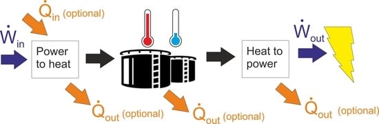
Carnot batteries (CB) comprise a set of multiple technologies which have a common underlying principle of converting the electricity to thermal exergy, storing it in thermal energy storage (TES) systems, and in a time of need converting the heat back to electricity. Based on this principle, alternative terms are also used as power to heat to power (P2H2P) or electric thermal (or electro-thermal) energy (electricity) storage (ETES). An excellent review work [23] provides a general overview of CB principles and therefore the reader is referred to this work for details. Prospects of PTES system are then provided in [24]. Here the general aspects will be therefore summarized rather briefly. A general principle of the CB is illustrated in Figure 2.
Carnot Batteries use surplus electricity as an input of a power to heat (P2H) system to create a temperature gradient (thermal exergy). It can have a form of hot and cold storage systems, or just one of those (hot or cold) with the temperature gradient defined against the environment. During the discharging process, the thermal exergy is converted back to work (electricity) by heat to power (H2P) system, in principle a heat engine. Various concepts of CB can be illustrated regarding the P2H and H2P conversion processes and thermal integration of the heat source in Figure 3.
The simplest concept is the direct conversion of electricity to heat, which is then stored before its conversion back to power during discharging, typically by a power cycle. Other systems can be considered so called compressed heat energy storage (CHEST) or pumped thermal energy storage (PTES) as they utilize the thermodynamic cycle (in principle a heat pump) for the P2H conversion. The first PTES in Figure 3b works mostly between two distinct temperature levels arbitrarily chosen and (theoretically) independent of the environment, having separate hot and cold storage systems. A specific aspect of CB is the possibility of thermal integration, both on the side of energy input as well as output, providing many possibilities for sector coupling. Regarding the heat input, the heat source can be either upgraded to a higher temperature, which is then used as a heat input of the power cycle or the charging system can prepare cold, which is stored and subsequently used as a heat sink of the power cycle during discharging, increasing the overall temperature gradient of the heat source [25]. A specific case can be defined when the Tsource is identical to the environment. Regarding hot storage, such systems are not really considered due to their low roundtrip efficiency. Regarding cold storage, it could be considered a highly simplified representation of liquid air energy storage, when the air is liquefied and stored at cryogenic temperatures. All real thermodynamic conversions depart from the ideal ones (e.g., minimum temperature differences in heat exchangers, efficiency of compressors and expanders, pressure drop in components). As a result, a portion of the heat needs to be rejected into the environment due to the irreversibilities [26]. The first concept (Figure 3a) minimizes the losses by converting and storing the heat at highest possible temperature, maximizing the power cycle efficiency. The second concept (Figure 3b) then optimizes the charging and discharging cycles to minimize the irreversibilities. In the heat source integrated concepts, efficiency is also a function of the temperature lift of the heat pump. With a very low lift, the roundtrip efficiency (defined below) can theoretically reach values above unity, in case of a zero lift (and work) of the heat pump, even going towards infinity.
As Dumont et al. [23] or Steinmann et al. [27] mention, there are many possible technological variations of CB. Charging can be realized besides direct conversion (joule heating) by any thermodynamic heat pump cycle. Discharging offers a similar range of options with heat engines to those of Brayton, Rankine or Stirling cycle, their combinations and also direct conversion as thermoelectric, thermi-ionic and thermophotovoltaic systems.
The first examples of these technologies can be traced to 1924, when Fritz Marguerre patented his own solution of thermal energy storage [28] or even to 1833 to work of Erricsson [23], but it has not been until the recent decade, when high volatility of electricity production and its mismatch with demand, it attracted wider interest in this technology. It typically provides relatively low efficiency in the range of 30% to 70% but also low cost for medium and long duration electricity storage. The widely increasing interest in CB was also a reason for establishing an IEA Task 36 on Carnot Batteries [29] with an aim of providing and unifying clear definitions, key performance indicators and classification of CB. Results of a short bibliographic study from Google Scholar using the main keywords of CB technologies shown in Figure 4 also confirms the trend of an increased interest in these technologies. At the same time, it shows that the unifying notation of these technologies as a Carnot battery is not yet in mainstream use.
CB as any electricity storage system is specified by its roundtrip efficiency (RTE), which is defined as a ratio between electricity produced during discharging and electricity consumed during charging, see Equation (1).
Alternatively, useful energy efficiency (also referred to as total efficiency) can be defined by Equation (2) as total useful energy output in the case of sector coupling, especially also providing heat and/or eventually cold. This heat can be used from the CB system in the charging phase, separately drawn from storage, but the highest efficiency is obtained if it is a by-product or rejected heat (possibly also its part) from the discharging phase.
Note that no heat input is considered even though in some CB concepts it is present. It can be argued that other formulations of efficiency may be also used. From thermodynamic standpoint, exergy efficiency explains the loss of potential and quality of all inputs in the best manner. This work however aims rather at an overview of CB technologies with respect to their prospective application and progress of scientific findings towards much needed commercialization. The heat input is moreover mostly considered as a low or zero cost input, typically in the case of waste heat with no alternative utilization.
1.2. Purpose of the Review
Throughout the increasingly extensive scientific research of the Carnot Battery technologies, commercial development is present as well. Examples of the main technologies were provided in the CB review [23] along with nine identified prototypes built between 2011 and 2020. Only some companies are publishing their findings and information about the CB systems directly in scientific publications as in [30,31]. A comprehensive summary of the CB technologies under commercial development is however missing. The present work addresses this gap, while the commercially developed technologies and presented parameters are also put into context with the approach and results in scientific publications. This provides both qualitative and quantitative views of this field of technology as a certain approach shared by multiple companies can be identified in some cases, while a certain approach is not, on the other hand, explored in the scientific literature. As a comprehensive technology review, it addresses the needs of both academics and industry practitioners, while it might in some cases bridge between these two, especially when pointing out technologies that are insufficiently addressed in scientific research or, vice versa, highly academically studied concepts with very limited industrial development.
1.3. Classification of CB Technologies
As was shown above, many classifications of CB concepts, principles and used technologies are available. The method of charging, discharging, thermal energy storage technology or the conversion system used can be named as examples. In this manuscript, classification by the discharging system is used, specifically as the Rankine cycle systems, Brayton cycle systems and other & hybrid systems. This is in accordance with the categories in the IEA Task 36 on Carnot Batteries [29]. Within each of these groups, further distinction is made between the systems with direct P2H conversion and with the PTES systems using a heat pump principle for charging.
Additionally, there are TES systems under commercial development, which are considered specifically for the CB application, mostly for direct P2H conversion and standard power cycle (Rankine or Brayton) technology. These specific technologies are therefore included as a separate section of this paper.
Within the list of the experimental systems, there are several levels reported. The first one is a proof of concept, largely scaled down system for demonstrating technical feasibility, often with poor roundtrip efficiency or other parameters. A demonstrator is then typically at a larger scale and better parameters but works at the manufacturer site with limited benefit of the operation or operated just for purposes of technical tests. A pilot is already installed on site and providing its designed services to its customer, though installation is largely or fully subsidized. Note, however, that this difference does not need to always be very clear in real systems. The last level is finally a fully commercial system.
2. Carnot Battery Development by Technologies
2.1. Rankine Cycle Systems
Rankine cycle systems can be further divided into steam Rankine cycles, which are predetermined to work efficiently at higher heat source temperatures and high power outputs typically in the order of dozens to hundreds MW and organic Rankine cycles (ORC), which are the domain of smaller power outputs and lower heat source temperatures up to several MW and possibly down to the kW scale. CO2 cycles, typically with transcritical operation, make up a specific category. Considering the underlying principle, even systems, where the Rankine cycle thermodynamic changes are separated to different time periods, are included here. A typical example is storing heat in a liquefied gas or vapor (latent heat), while the gas itself is a working fluid in the thermodynamic conversion.
Table 1 comprehensively summarizes the CB systems utilizing the Rankine cycle for its discharge phase in the scope of commercial development (or having some commercially oriented aspects). They are sorted according to the power to heat conversion method to the resistance heated systems and fully reverse systems; then by working fluids from water to organic fluid, air and CO2 and finally to systems with a Rankine cycle heat pump as a full cycle and the systems with part of the heat pump cycle with liquefaction and storage of the working fluid. Note that eight out of 13 reported systems are conducting experimental, demonstration or even pilot operations of their systems.
2.1.1. Electrically Heated RC Systems
Joule heating makes most technical sense in combination with a steam Rankine cycle. No other working fluid is considered in these directly heated systems. The reason, except for being the industrial standard, can be found in its higher efficiency compared to ORC systems and the fact that CO2 cycles at high temperatures have seen only very few demonstrators built so far (e.g., CSP application [57] or Allam cycle for gas combustion [58]). Technically, the direct heating with steam cycle can be considered as the simplest technology. Furthermore, all electrically heated systems under development include the possibility of converting existing coal fired power plants to storage systems, utilizing the existing infrastructure and saving the typically costliest components of the CB, which is the power cycle unit. The system of this type is referred to as a straight forward one in [59] and the possible scale in the case of a fossil fired plant’s partial refurbishment for increased flexibility or complete refurbishment can be found in [23].
Regarding the power output, electrically heated systems are well scalable, with the limitations provided by steam cycle systems. The smallest systems in the MW scale can be applied for example in CHP plants; as solely power to power CB, Siemens Gamesa with an output of 1.2 MWe serves only as a demo. The largest systems can theoretically consist of blocks of several hundreds of MW each. Electrically heated storage is limited by relatively low roundtrip efficiency, which is determined mainly by the H2P conversion technology (power cycle efficiency) since the electric heater is employed for charging. Furthermore, the other losses occur during operation, namely heat loss into the environment and the pressure drops.
The first small scale Gamesa ETES test rig was built in Bergedorf in 2014 with 5 MWh storage capacity and a 750 kW gas burner. Its purpose was the testing of various storage concepts, materials and setups. This testing unit has run for over 2500 h [32]. Owing to the constructed full system demonstrator, the ETES system of Siemens Gamesa commissioned in 2019 in Hamburg is perhaps the best known; first and so far, the biggest constructed system of this kind. The system uses a horizontal flow packed bed of volcanic rock and air as a heat transfer fluid. With a maximum storage temperature of up to 750 °C the system has 130 MWhth storage capacity. Volumetric storage capacity reaches approximately 0.2 MWhth/m3 (depending on charge-discharge temperature spread) and its great advantage is in high technology readiness level (TRL) due to the use of commercially available components, the resistive heaters from process industry and heat recovery steam generators (HRSG) utilized in combined cycle power plants. The storage concrete construction vessel is filled with about 1000 tons of crushed volcanic rocks and thermally insulated by aerated concrete and rock wool insulation [32]. The system was designed for 24 h charge and 24 h discharge operation. The rather low roundtrip efficiency (around 25%) is due to the steam cycle efficiency (small scale, low pressure) and auxiliary loads, especially air fans.
Thermal losses can be minimized by optimizing the amount of thermal insulation according to the economics. Pressure drops can be mitigated by packed bed construction and operation (air flow velocity, particle shape and diameter and vessel length to diameter ratio). Nominal storage capacity can further decrease by de-stratification effects due to heat transfer in a packed bed in a charged state [60] (reported for horizontal flow stores). Hence the storage unit must be oversized, which leads to an increase of thermal and pressure losses. Unlike in coal plants, parasitic loads related to its handling or boiler efficiency are however excluded here. The efficiency is expected to significantly increase in larger scale installations to over 42% [33,34,60]. Currently, Gamesa is ready for building the first series of commercial pilots in a range of 10–100 MW power; 100–2000 MWh storage capacity and 300–720 °C steam temperature [32].
The ETES system offers various applications, such as integration into existing power plants or combined heat and power plants, rebuilding conventional fossil fuel power plants into storage units or electrification of process heating. Therefore, Siemens Gamesa has been developing three market types of storage application, for the conversion of fossil power plants, adding storage to existing thermal systems (industrial plants for process heat electrification and heat recovery) and a whole stand-alone system supplying process steam, electricity or district heating [60].
Looking at the chosen horizontal configuration, much smaller scale investigations of rock bed TES found very strong effects of buoyancy, having a detrimental effect on temperature stratification and the utilization of the thermal capacity of the entire volume, further confirming the de-stratification effects. Either the TES capacity is then limited or additional horizontal air tight layers need to be added to the storage tank to maintain air flow uniformly through the entire volume [61].
Similar is the intended application scale of RWE’s development, which is, with its project StoreToPower, focusing on an alternative technology of molten salt, adopted primarily from concentrated solar power plants (CSP) and, secondarily, also on solid materials with air as a heat transfer fluid [35]. However, no further public information provides any insight on the ongoing status. Focus on molten salt appears to be a logical choice as in the CSP plants it is a well proven commercial technology [62,63]. With the molten salts, special attention needs to also be paid to corrosion, especially at temperatures above 500 °C [64,65], which are typically found in coal fired power plants.
A P2H2P system with direct electrical heating primarily suggested for refurbishment of coal fired plants is offered by E2S Power [36]. The TES system is using an alloy (miscibility gap alloy, MGA) composed of graphite and aluminum and developed by a partner MGA Thermal. The MGAs are commonly proposed as a novel type of TES material with some unique properties such as macroscopically solid materials safely embedding PCM, providing combination of sensible and latent heat and with high thermal conductivity [66,67]. Blocks of the MGA are electrically heated during charging, half up to 700 °C while the second half only to temperature required by the steam turbine. The colder blocks then, during discharging and steam generation, serve for self-regulation of the steam outlet temperature. A laboratory system has been built demonstrating the TES with charging and steam generation, while plans exist for a 50 MWhth pilot at a coal power plant in Montenegro.
2.1.2. Reversible RC Systems
Reversible systems use the principle of a vapor compression heat pump in the charging phase and standard RC during discharging. Various configurations were proposed theoretically for steam systems with a suggestion to further improve the roundtrip efficiency by integration of heat sources to the heat pump input [68]. Together with the additional possibility of various working fluids (steam, organic fluids, CO2), direct or indirect use of the cycle working fluid for storage and choice between latent or sensible TES, there is a wide range of available technologies.
Starting from the most typical RC using water as a working fluid, the company Spilling, manufacturer of steam turbines, compressors and engines, entered into the development of CB. The system consists of a reversible steam engine/compressor and two steam accumulators, one at low pressure and other at high pressure [37,38]. A major advantage of such system is a combination of existing technology of steam engine from the company portfolio, while steam accumulators are a well-established technology over hundred years old. The accumulators however require relatively large, pressurized tanks for the saturated water. This makes the technology of steam accumulators suitable rather for industries and small power plants; one of the largest applications is a 20 MWth (50 min at 5.5 MWe) application for a CSP plant. The addition of PCM to the tanks is proposed to improve the thermal capacity at the same volume. A drop in the pressure during the discharging of the tanks is another disadvantage [69,70]. For the CB applications, a similar size can be expected as that for similar systems for small steam parabolic trough flexible plants as 2 MW/6–24 MWh units [71]. The pressure drop loss might be partly compensated for by sliding pressure in both charging and discharging process. Investigation of parameters of this CB concept are not, to the authors’ knowledge, supported by any scientific literature.
GE has in the past proposed a system using a recuperated CO2 Brayton cycle operating as a heat pump for charging with a steam Rankine cycle discharging as an advanced molten salt electrical storage system (AMSESS). High temperature heat is stored as a molten salt while low temperature heat input is provided from a water tank and the water is thus cooled down. An additional electric heater can be used to increase the salt temperature. During discharging, heat is transferred to the steam cycle, where most of the rejected heat goes into the environment, while a smaller portion such as a turbine bleed heats up the water tank. A design with off-the-shelf components has been performed for 20–100 MWe power output over 8 h period with RTE ranging based on size and presence of the heater between 42% and 62%. An interesting note is that the space requirements are about one third of the same capacity in containerized lithium batteries [39].
Another set of technologies builds on standard heat pumps and subcritical organic Rankine cycles. These systems are specifically considered as well fitted to waste heat sources, or other low temperature heat sources, such as solar collectors or geothermal heat. The availability of the heat source then decreases temperature lift of the heat pump (or provides a heat source in less considered concept, where the heat sink is below ambient by cold energy stored and prepared in time of excess electricity by refrigeration cycle). Roundtrip efficiency can, as a result of heat input, theoretically exceed 100% [72]. Regarding the size and cost, storage tanks need to be carefully considered as in the case of low temperature glide; even a small power output requires large tanks, which might be costly for long duration storage. The power output can be expected from dozens kW up to no more than several MW as is the size of large CHP or geothermal ORC systems [73]. This concept gained much research attention, where theoretical investigations are performed in many institutes and several experimental systems are in experimental operation or under construction [74,75,76], all in kW scale.
Looking at the commercial development, the list is, however, rather short. Within the CHESTER research project [40], universities join research institutes and companies to focus on business models and market opportunities for such application, meanwhile one industry within the project, for example, focuses on the development of an isobaric expansion device considered for one of the concepts [77]. The main CB concept utilizes both sensible and latent heat storage to maximize efficiency and match temperature profiles during charging and discharging, while providing thermal integration to district heating. A kW scale experimental system is under development. Similarly, ORC unit manufacturer Climeon offers its units of output around 100 kWe for CB applications with storage also proposed as district heating infrastructure including large seasonal storage tanks and up to MWe size total output. Additionally, greenhouses and geothermal systems are suggested as application cases for CB. Except for the ORC conversion unit, the system is however in a conceptual state [41]. Another example is a heat pump manufacturer, TC Mach, developing together with a university a high temperature heat pump, TES. made of compacted stone dust and an ORC, where the constructed proof of concept unit is going to be sub-kW scale [42].
The only larger scale ORC CB system in state of a pilot application is developed by Futurebay [43]. This system is considered in several applications, with or without thermal integration of waste heat source. Without any external heat source, a heat pump is used to charge both hot and cold storage during a period of excess electricity and these stores are then utilized separately. Heat is stored in hot water tank while PCM storage (probably ice based) is used for cold storage. Both hot and cold can be used directly or the ORC can run between present temperature gradients—hot store and ambient (eventually space heating temperature) or waste heat to cold store. The system is considered primarily for integration into thermal systems with both cooling and heating requirements. A containerized demonstrator delivering 50 kWe/200 kWhe and cooling capacity 2 MWhth has been built and operated; scalability is however suggested up to a 12 MWe/72 MWhe grid scale system.
Liquid air energy storage (LAES) is in principle also a Rankine cycle as it utilizes the phase change of the working fluid for storage and especially in the discharging phase, a typical cycle’s heat input/output takes place. The working fluid is at the same time also a storage media in an open cycle. The air is compressed and liquefied during the charging by a relatively standard industrial technology. Special attention is paid to the conservation of thermal energy during the liquefaction process, both cold and hot, as it is essential for the high roundtrip efficiency of the system. Thermal energy is in this concept stored therefore threefold—in the liquefied air and near-ambient pressure as latent heat, thermal energy recovered after compressors’ outlets and cold energy from the gas cooling before expansion and from recycled streams.
The advantage of LAES lies in relatively small storage volumes (in the order of 700 times smaller than those required for CAES) due to the higher energy density in liquid air. The LAES system also relies on commonly used components in industry (compressor, liquefier, turbine, etc.). Today’s studies show that it is possible to achieve roundtrip efficiencies around 70%, with a specific investment cost of 1270–2090 €/kW [78]. To date, several studies have been published on various LAES configurations. In [79] they proposed integration with a conventional combined cycle power plant; in [80] they studied the LAES system integrated with a nuclear power plant, and many publications paid attention to the recovery of waste heat from LAES using ORC, which increased RTE by up to 12% [81,82,83].
The only commercial development is carried out by the British company Highview power. In 2011 their first pilot plant was launched (350 kW/2.5 MWh), which was tested on a biomass plant site and is now located at the University of Birmingham. The achieved roundtrip efficiency was only 8%, therefore the second Pilsworth Grid Scale pilot power plant (5 MW/15 MWh) was built in 2018. Highview power is now developing a 50 MW commercial plant in Carrington Village with a storage capacity of 250 MWh in cooperation with MAN Energy Solutions. The commissioning is expected in 2022 [44,45,46]. Another project is planned with the expected start of construction in 2023 in Chile with a power rating of 50 MW and a capacity of 500 MWh [84]. In the future, Highview power plans to offer LAES systems in a relatively large range of outputs from 20 MW/80 MWh to more than 200 MW/1.2 GWh [85].
Rather favorite among CB appears to be the utilization of CO2 cycles, which otherwise struggle to find their place in other energy systems. Development of the ETES system of MAN and ABB aims at a very peculiar and rather low temperature system with a reversible transcritical CO2 Rankine cycle. The system has the highest storage temperature only around 120–150 °C utilizing pressurized water and cold storage, and using ice as PCM. The hot storage system is divided into four tanks at different temperatures into which the heat is transferred via three separate heat exchangers. It is to balance the optimal mass flow rate and heat exchange temperature profiles due to the change of the supercritical CO2 heat capacity, while the temperature differences along the whole length of the heat exchangers are designed in order of several Kelvins. Only one hot water tank needs to be pressurized, while the pressure is still moderate. During charging, part of the energy in high pressure CO2 is recovered by a hydraulic turbine while rest below the saturation line is flashed to exclude the issues of two-phase expander. The resulting system is then a result of many techno-economical optimizations under constraints of isentropic efficiency of key turbomachinery components (the company’s state-of-the-art) with the roundtrip efficiency reaching values of 38%–50%. The target size is an 8.5 MWe system with 8 h charging. Development of this system is well documented in [31,47,48,49]. Currently, an MW scale laboratory demonstrator has been developed to test the system and equipment. The commercialization strategy aims at the possibility to use also standalone system of only heat pump or heat pump with storage, able to provide 5–50 MWth of heat (3–30 MWth cooling) with 2–15 MWe power input. As such, a 50 MWth seawater heat pump for district heating using this technology is to be built in Denmark by 2023 [86].
The MAN–ABB consortium is not the only one representative of CO2 cycle utilization, even though they are clearly closest to application. Echogen [50], known mainly for its waste heat recovery 8 MW unit with CO2 as a working fluid is also working on a CB system for more than 4 h and 10 MWe size. Available information discloses a concept utilizing the CO2 reversible recuperated cycle, low temperature storage also being ice/water storage (as brine for −2 °C to −10 °C) and high temperature storage being at 300–350 °C in the form of sand in silos or alternatively concrete blocks. The temperature has been selected to be within the limits of standard construction materials [51,52,53]. A proof-of-concept in a 100 kWth scale heat pump and sand storage and heat transfer system has been developed while a 25 MWe 8 h prototype system is in a design phase [54].
The CO2 has been also proposed for a system using a similar principle to the LAES by the company Energy Dome [55]. The gaseous CO2 is stored at ambient pressure in a large container (dome). During charging, it is compressed, liquefied and stored in tanks, while the heat (from intercooling and condensation) is separately stored in a TES. The discharging process then reverses the flow, high pressure CO2 is evaporated by the stored thermal energy and expanded in the turbines back to the low pressure gas store to produce the electricity. The sequence of charging and discharging can be considered as thermodynamic changes in an open Rankine cycle. To maintain constant conditions at the compressor inlet, a flexible membrane is employed within the dome. TES is separated into five sections at different temperatures in configuration with a multiple section compressor and turbine with intercooling and reheating. Main advantages of this concept are mentioned as high energy density at moderate pressures. The calculated net roundtrip efficiency can reach about 77% [56]. Note that similar systems were proposed before, but with liquid CO2 storage at a low pressure and with a maximum roundtrip efficiency of 57% [87]. The system has recently progressed from a concept with basic sizing and costing to the construction of a 2.5 MWe/4 MWh pilot system scheduled to be finished in 2022 and in the same year there is planned the start of a full-scale 20 MWe/100 MWh system construction [88].
2.2. Brayton Cycle Systems
Brayton cycles are favored for applications with sensible heat TES materials as during the isobaric heat addition and rejection, it is possible to obtain a well matching temperature profile, minimizing exergetic losses. Other advantage can be the maturity of the gas turbine industry, from which many systems are derived. The summary of the commercial development in Table 2 shows that the extent of the projects is smaller than in the case of the Rankine cycle systems (opposite trend to the publications numbers in academic research). It can be argued that one reason is in the requirement of very high efficiency of compressors and expanders to which the systems are highly sensitive, while such components have a limited industrial supply.
2.2.1. Electrically Heated BC Systems
In order for the electrically heated Brayton cycle to be efficient, very high storage temperatures need to be reached, namely exceeding 1000 °C. However, the need of reaching such a high temperature for increase in roundtrip efficiency also leads to material constraints. Considering a parallel to the scientifically reported development in Brayton based PTES, interestingly, a very small number of publications is focusing on this concept.
A U.S. company, 247 Solar, provides a concept of an electrically heated CB, which combines subsystems named the 247Solar Heat2Power Turbine and the 247Solar Thermal Storage System. These subsystems are proven in CSP applications (Brayton based solar towers), where there is a specific solar irradiation receiver and vertically orientated thermal storage, both using air as a heat transfer fluid operating under conditions of near ambient pressure and high temperatures (970 °C) [90].
During charging, the electric heater (resistance coils) is employed for heating the air flow by using a blower, both supplied by surplus electricity, and afterwards the air passes the heat to the sand thermal storage. The discharging process employs a classic open loop Brayton cycle, meaning that the inlet ambient air is compressed, then heat is supplied in two heat exchangers (low and high temperature) and next the air expands in the turbine. To increase the overall system dispatchability, a burner for various types of fuel (including hydrogen) can be added. The presented roundtrip efficiency of this system amounts to 30%, nevertheless the combined heat and power production efficiency can reach more than 90%. 247 Solar considers standard configuration with nominal 200 kWe power output and thermal storage capacity 1.8 MWh that corresponds to 8–10 h duration. This project is evolving in collaboration with Capstone Green Energy, the provider of customized microgrid solutions and on-site energy technology systems [96].
1414 Degrees Limited is an Australian company, which develops Thermal Energy Storage Systems (TESS). The novelty of this system lies in using molten silicon PCM with melting temperature 1414 °C, which enables reaching high energy densities and potentially high efficiencies of conversion back to electricity and usable heat [89].
For the charging of TES, an electric resistive heater is utilized. Another option for heating the molten silicone storage is combusting gas, for instance, methane generated from wastewater plants. The advantage of using silicon is in its high latent heat capacity in comparison to other PCMs. The silicon’s sensible heat capacity below the melting point is up to 300 kWh/t; nevertheless, the latent heat supplied during the solid to liquid phase change at the constant temperature of 1414 °C is about 500 kWh/t. The operation of TES at such a temperature brings many material challenges. However, several well-established industrial processes are treating material with very high temperatures, for example the cement industry temperature level exceeds 1400 °C. Therefore, 1414 Degrees implements materials and technology knowledge from these proven technologies. The discharging process can be achieved by several conventional heat engines, where the most effective plants achieve over 60% thermal efficiency. Hence, 1414 Degrees considers four options of discharging. In terms of combined power and heat production for reaching the maximum overall roundtrip efficiency, the gas turbine, steam turbine or a Stirling engine can be employed; lastly, a steam generator or heat exchanger can provide steam or hot clean air for industrial processes [89].
The TESS is designed as a modular system; when connected in series it increases the power output and in parallel configuration the storage capacity rises. 1414 Degrees plans four main commercial applications; one oriented on bulk medium-long term energy storage, one providing medium scale energy storage for industries and residential developments requiring power and heat. The last one is developed to accommodate combustion waste gas (e.g., sewage treatment) and store the thermal energy for later recovery (for electricity and heat). As such, it is similar to the industrial application but with modified charging. Lastly, the TESS industrial system producing steam is best fitted for industries with high thermal rather than electricity demand, especially for replacing natural gas with renewable sources. Using a steam turbine for electricity generation is only secondary [91], but possible for example using extraction turbines providing also heat at lower parameters.
1414 Degrees built up the first demonstration plant in 2016 and is still operating it in its R&D facility in Lonsdale, South Australia. The demo comprises of 200 kg silicon PCM storage charged by 50 kW heater and was using 43 kW Stirling engine for discharging, in 2018 replaced by a gas turbine. In 2018, a 10 MWhth GAS-TESS module was also put in operation at the Glenelg Wastewater Treatment Plant. The next step of 1414 Degrees is to acquire SolarReserve Australia II, which owns the Aurora solar project [97]. The current plans of the Aurora project, led by the 1414 Degrees company, are to build up a 70MW PV farm and 150 MW CSP plant, coupled with several thousand MWhth storage capacity [98].
The use of a supercritical CO2 in a BC has been proposed by Peregrine Turbine Technologies as a CB along several other use cases [92]. The system uses the MGA from MGA Thermal as already considered in Rankine cycle systems from E2S, here with temperatures of 800 °C. The power cycle uses a partially recuperated configuration with compression from right above the CO2 critical point [99] and the whole system is designed as a 1 MWe modular system with a storage capacity of either 8 MWhe or modular with 5 MWhe increments. The unit has an expected CAPEX of 280 $/kWh and a lifetime of 20 years. The company has tested their compact turbine with a CO2 compressor and plans full scale pilot construction for 2022 [92,100].
Contrary to these commercially developed systems, in the scientific literature the only application of the electric heaters with respect to the Brayton cycle has been considered in the form of additional upgrade and control of the gas temperature at the compressor outlet in works such as [13]. The purpose of adding an electric heater is the increase of the maximum storage temperature of the hot reservoir that increases the efficiency of the reconversion of heat into work during discharging and also significantly increases the energy storage density. Nevertheless, the implementation of an electric heater during charging leads to a reduction of the COP of the Brayton cycle heat pump, which may cause a decrease in roundtrip efficiency. As such, it is later shown to be proposed in the conceptual phase of one commercial reversible system development.
2.2.2. Reversible BC Systems
The development of a company, Isentropic Ltd., focused on a Brayton cycle using a reciprocating reversible piston machine capable of working as both compressor and expander together with a fine gravel storage in hot pressurized tank and a cold tank at ambient pressure. The company itself, established in 2012, was placed in administration in 2016, before finishing its “grid scale” 150 kW experimental demonstration system. It serves as an example of the consequences when the market is not yet ready for the developed systems. Many lessons and information can be learned, as much of the technological development has been scientifically reported. First, three small prototypes and the conceptualization of a commercial size unit were reported in [93]. The development, originally conducted with Newcastle University, was consequently picked up by Durham University, where the 150 kW demonstrator was built and experimentally tested [101].
The piston compressor/expander component utilizes a uniquely developed sliding valve approach, which is designed to minimize the pressure losses, reduce dead space, provide a high quality seal without excessive precision requirements and a very fast valve actuation speed [102], which under electrical control allows for a rapid change from charging to discharging regimes in less than one second. The storage is composed of a stack of grates with magnetite sand (~1 mm) with actively controlled flow only through the selected ones and bypassing others to limit pressure drop. The designed working fluid, argon, has been for the tests substituted by nitrogen due to leaks and the system was operated at reduced pressure, speed and power. The 150 kWe designed system was operated at about 10 kWe charging and discharging power, still reaching roundtrip thermodynamic efficiency (drive excluding mechanical and electrical losses) around 77%, while the prospect of likely final system performance with argon at full speed has been determined from the data as 73% roundtrip efficiency at about 125 kWe charging and 100 kWe discharging power [101]. The originally intended scaled up 2 MWe/16 MWhe commercial (modular) unit was analysed to have a LCOS of 9 to 11 €ct/kWh including given purchase electricity price and 2 to 5 €ct/kWh excluding them, while CAPEX were 350–797 €/kWe of power and 13–21 €/kWhe stored [103].
The concept developed by the company Malta follows an approach detailed by Laughlin [26]. The described concept is based on a closed Brayton cycle, which is transporting heat from a cryogenic fluid storage to a molten salt reservoir, when it operates in the charging regime. In discharging mode, the heat flow is reversed and runs the gas turbine, so the electricity is supplied back to the grid, when demanded. The Laughlin’s storage system consists of a compressor, an expander, two molten salt hot storage tanks and two hexane coolant cold storage tanks, two heat exchangers for heat transfer between the heat transfer and working fluid (HTF) and a recuperator.
This system was developed in the early stages by Professor Laughlin, the company Brayton energy and Nick Cizek, who designed the baseline of closed cycle gas turbine with Ar (or He) as a working fluid and later sold the rights to Google’s (Alphabet) moon-shot factory X in 2016 [104]. After two years of incubation in X, when the potential of the grid scale storage technology cleared up, Malta became an independent company [105].
Nowadays, the novel Malta system, named Pumped Heat Energy Storage, is based on a closed loop, recuperated Brayton cycle. The purpose of recuperation is to get better minimum and maximum storage temperature spread (based on industry experience) and an increase of efficiency. The maximum temperature 570 °C is limited by material creep and corrosion, while the minimum temperature of −70 °C is set by material embrittlement and air (working fluid) drying requirements [106]. Malta’s final goal is a full scale 10–100 MWe facility in 2024, enabling the low-cost storage (unit CAPEX less than $100/kWh). Malta is currently developing a kW-scale demonstration facility, which should help with understanding the limitations of operational modes (start-up and shut down), especially the validation of transient analysis. This demo is characterized by lower costs and risks, due to its small scale. Contrarily, the small scale of turbomachinery and temperature limits of storage media causes significant roundtrip efficiency disruption, so the prediction of RTE is 10% [107]. Malta has also signed a term sheet with Canadian utility NB Power about establishing an Energy Storage Benefits Agreement to advance the first long-duration energy storage facility in the New Brunswick province. The planned 1000 MWh facility would help to achieve New Brunswick’s emission reductions, improve grid stabilization, increase the integration of renewables, and bring new jobs into the region. However, the project of the storage facility is still in the early stages, the target year for the start of operation is 2024 [108].
GridScale is the official name of the concept developed by Danish company Stiesdal. Stiesdal’s goal is to develop a storage facility for cost-effective electric storage, which is scalable and based on industrialized components. The application field of GridScale is a medium duration storage, which more specifically balances day-to-day production of photovoltaics (12–18 h) and smooths the wind farms production on several days (3–7) periods. GridScale is a reversible Brayton cycle Carnot battery, which uses low cost crushed rock packed beds as thermal storage and offers relatively high roundtrip efficiency without location limitations [94].
In the charging regime one pair of compressor-expander is employed for pumping the thermal energy from cold reservoir into the hot storage, due to the use of surplus electricity from the grid. The maximum temperature of hot reservoir is 600 °C and the minimum temperature of cold tank is designed at −30 °C. The COP of Stiesdal’s configuration is determined approximately on 2.5 (depending on the temperature levels). During discharging, the system is operating as a regular gas turbine (Brayton cycle) with another similar compressor-turbine system for charging. The predicted efficiency of the gas turbine during discharging is 20%–25%, also depending on the temperature ranges. The range of GridScale’s roundtrip efficiency, derived from COP and Brayton cycle efficiency, is 55%–60%. The useful energy efficiency could be increased to roughly 90% by using the rejected heat from the cycle during charging for district heating [94].
The project GridScale has been supported by grants and subsides and is developed in a partnership with Andel, Aarhus University, Technical University of Denmark, Welcon, BWSC, Energi Danmark and Energy Cluster Denmark [109]. The numerical models of GridScale have been validated under various conditions since 2019 at the test facility with a 1:10 scale steel tank. This demo facility reached similar heat transfer from heat transfer fluid (air) to storage media (basalt crushed rock) as theoretically modelled, and achieved even lower pressure drops than expected [109]. In terms of the serial manufacturing of storage units, Stiesdal can utilize extensive experience from welding the tubular steel towers of wind turbines. The company Stiesdal is preparing a demonstrational project, which will be placed in Rødby on the Danish Island of Lolland and installed next to Rødby’s district heat and power plant. This demo plant is planned to operate in commercial regime with a 4 MWe/2 MWe charge/discharge power and 10 MWhe storage capacity [94].
Enolcon GmbH in [30] presented their own Brayton based Carnot battery called OPTES Battery. The baseline design of OPTES consists of common closed Brayton cycle components: expander; compressor and two sand packed bed storage units and two heat exchangers. Alternatively, the bottoming ORC cycle using otherwise rejected heat after expansion in discharging regime can be added, in order to increase roundtrip efficiency. In the case of sufficiently cheap electricity input, an electric heater is a feasible solution for “boosting” temperature before inlet to the hot tank during charging. That enables a high level of temperature regulation, nevertheless it also causes a drop of roundtrip efficiency. The silica sand packed bed is developed by Enolcon’s partner STORASOL GmbH and has been demonstrated together with an ORC unit, named the ORCTES-plant, at the University of Bayreuth in Germany, where it has been in operation since 2015 [110]. The parameters of this demonstrator are 1.5 MWhth storage capacity, 1.8 MWth of charging power and 600 °C operation temperature of the storage [111].
Currently, Enolcon is developing a proof of concept of the OPTES Battery power plant, which they plan to launch in 2023. Their CB should be able to reach approx. 40%–45% roundtrip efficiency even with off-the-shelf equipment. But the goal is to develop companders (devices combining turbocompressor and turboexpander) with nitrogen as a working fluid in a cooperation with Atlas Copco, which sustains higher pressures and temperatures above 715 °C and therefore reach higher efficiency. Hence, the CB with advanced turbomachinery achieves roundtrip efficiency roughly around 63%–67%. However, it is necessary to mention that the considered isentropic efficiencies in the described model are relatively high, specifically 93% for the expander and 91% for the compressor in a “realistic case” [30].
The capital expenditures (CAPEX) of OPTES Battery with a storage capacity of 80 MWhe and electrical storage power of 7.6 MWe were specified for 16–20 million EUR, meaning that the specific installation costs of electricity storage of such a system are estimated at 200–250 €/kWhe. In comparison, the specific costs of electricity storage of current commercial large-scale Li-on battery storage in Germany are according to [30] approximately 450 EUR/kWhe. Specifically, the Li-on battery project in south-eastern Brandenburg with 53 MWhe storage capacity and CAPEX of 25 million EUR, which was under construction in 2020, is mentioned. The determination of CAPEX is coming from the market prices based on Enolcon’s knowledge in project management, engineering and design of large technical facilities (process systems, power plans, etc.) [30].
Lastly a CB system designed specifically for integration into the wind turbine is a system designed by WindTP [95] in cooperation with the University of Nottingham and the University of Leeds [112]. The system is thus primarily charged not by electrical power but instead by the mechanical power of the wind turbine shaft. The work can be transferred directly to generator via subsequent expander as aerodynamic coupling. When energy storage is required, shaft drives a low speed multiple stage high efficiency piston compressor to compress the working gas from 2 to 50 MPa and around 600 °C. A separate optional compressor supplied with electricity from the grid may be included as well. After heat transfer to the hot storage, expansion takes place and cold energy is stored as well. Rock bed is assumed as both hot and cold TES. Research has shown a feasibility of this solution for wind turbines when the stored electricity accounts for at least 25% of the produced power. A specific multistage slow speed piston compressor concept is proposed for high efficiency [113], which is currently in experimental development [7] and can be utilized not just for wind direct driven CB but also CAES systems [114].
2.3. Other Cycles & Hybrid Systems
Other and hybrid systems classification can be also divided into the electrically heated ones and ones using reversible cycles. Their commercial development is comprehensively summarized in Table 3. One can notice a presence of proofs of concept and pilot experimental systems and even already started commercial applications, surely a positive indication towards CB applications. A specific aspect of this group of technologies is that the heat to power conversion is performed not only by thermodynamic cycles, but also by systems of direct conversion.
2.3.1. Electrically Heated Other & Hybrid Systems
As with electrically heated RC or BC systems, electric resistance heaters are used in these systems for charging. The discharge can be realized either by thermodynamic cycles, for example by a Stirling engine or a combined Brayton with Rankine cycle, or by technology based on the direct conversion of thermal radiation to power (thermos-photovoltaic cell, multi-junction photovoltaic cells or hybrid thermionic photovoltaic cells). Thermal energy in these systems is stored at temperature levels from 600 °C up to even 2400 °C. All the systems can be therefore classified as high temperature ones.
Systems using a Stirling motor as the discharge method can be an interesting alternative to electrically heated RC and BC systems specifically for low power output in range of several to dozens kW and providing combined heat and power output. The development is probably furthest at the company Azelio, which has, for example, pilot installations in Morocco and Abu Dhabi and is already delivering first commercial units [126]. The system is using a sodium circuit as a heat transfer fluid to deliver the heat from recycled aluminum-silicon alloy PCM to the Stirling engine. The unit provides 13 kWe and heat at temperatures 55 to 65 °C over 13 h of storage capacity. Systems up to 100 MW are suggested to be comprised of multiple modules [115]. Development of this system is well documented from previous application of this Stirling engine technology and TES for CSP systems [127,128], while the Stirling engine development can be traced even to submarine systems [129]. Based on these sources, the roundtrip efficiency of this CB system can be estimated at around 30%–40%. In CHP application, the useful energy efficiency is around 90%.
A similar system has also been suggested for balancing small scale renewables in [130], where the considered engine has efficiency of only 21% at 2.5 kWe output without thermal output (cold cylinder at 30 °C). Thermal oil, molten salt and sand were explored as a storage material and economics was evaluated under a selected operation regime. The development of similar CSP applications using Stirling engine systems, often including various TES types, can be found in a number of other scientific publications [131,132].
This can be seen as the reason the Stirling engine also became the subject of quite a number of other commercial CB developments. Among them is the CCT Energy Storage, which unveiled its pilot project in March 2019 and was on track to install its first commercial facility [133]. The system uses phase changes of silicon to store thermal energy (PCM), which is then used to generate electricity using a Stirling engine. The installation can scale from 5 kWe applications to a theoretically unlimited size and the estimated cost is only 60%–80% of the cost of equivalent storage with lithium-ion batteries [117].
Stirling engine can be coupled also to suitably sized thermochemical (sorption) TES and work as a CB as shows the company TEXEL Energy Storage. Its system is based on the V4-Stirling converter, originally developed by Ford Motors. The Stirling converter produces approximately 40% of electricity and 50% of thermal energy, which adds up to 90% of total energy efficiency [118]. The second basic element of the TEXEL system is the thermochemical thermal energy storage. The company uses technology based on metal hydrides. The advantage of metal hydrides is the high energy density and the ability to work with temperatures above 600 °C. The TES consists of two parts, a hot part containing high temperature metal hydride (HTMH) and a cold part containing low temperature metal hydride (LTMH). When charging the TES system, hydrogen desorbs from HTMH and the desorbed hydrogen is then stored in LTMH. During discharge, hydrogen is absorbed back on the HTMH side, releasing heat to drive the Stirling converter [134]. For example, according to [135], it is possible to use a material pair of CaH2 and TiFe with the possibility of storage in the temperature range of 800 to 1000 °C and with a TES price of $ 15/kWhth. Useful metal hydrides can furthermore be, for example, NaMgH3 or TiH2. TEXEL also started the development of TES technology based on metal carbonates MCO3 where M is the metal cation (Mg, Ca, Sr, Ba, or Pb). This system works similarly to the metal hydride technology but uses CO2 as its working gas instead of H2 [118,136].
Another proposal of Stirling engine is a project of Kraftanlagen München in cooperation with Solar—Institut Jülich, Germany. It is a combined heat and power project with the useful energy efficiency of up to 80% (roundtrip efficiency unspecified). Electricity production is to be ensured through a combination of Stirling engine and ORC. The multifunctionality of the device should consist in the choice of heat source-either electric heaters or waste heat. The system is using a ceramic TES system with intended more versatile application [119,137]. The TES system is also marketed and described separately among the TES systems for CB in following section.
Only one scientific work focuses on an investigation of CB systems involving Stirling engine on a system level [130]. Separate description of major components as TES or conversion systems is not uncommon, though originally for different applications. This shows also the dynamics of the CB development, which can effectively repurpose technologies from different applications, typically, but not only, CSP.
A technology using electrical heating with TES temperatures around 1200°C, which uses a combined cycle of gas turbine and steam cycle for discharging is investigated in an NREL research project, ENDURING, with the strong involvement of GE and Babcock and Wilcox on a power cycle and the component manufacturing side and Allied Mineral Products, Inc. focusing on TES. The TES consists of a silica sand, which requires specific particulate handling system and heat exchangers based on fluidized bed principle. Techno-economic analyses are performed for a 50–400 MWe and 10–100 h of duration with the LCOS estimate below 0.05 $/kWh. With the combined cycle and high temperatures, the roundtrip efficiency has set a baseline at 50% with a technological prospect of around 55% gross efficiency. Hardware-wise, laboratory prototypes of the components are being developed and plans aim towards MW scale pilot demonstration [120,138]. The concept of storage in hot sand is also based on previous projects aimed at the CSP application [139].
A specific approach with the integration of the CB principle into a combustion gas turbines combined cycle has been taken by Pintail power. Its first system uses electrical heating of a molten salt, which is then, during discharging, used for the evaporation of the water in the bottoming steam cycle [121]. This approach can substantially increase the steam cycle power output and provide a good temperature match between the flue gas and water in the heat recovery steam generator. The second system is a hybrid LAES system, where the air is liquefied during charging. During discharging the cold fluid is then used first as a heat sink of a bottoming ORC, then to pre-cool the combustion air before it is finally heated by the flue gas and expanded in an air turbine [122].
The last group of technologies in this section are technologies that do not use a thermodynamic cycle for discharge, but various types of direct heat to power conversion-thermophotovoltaic cell, specifically modified multi-junction photovoltaics or hybrid thermionic photovoltaic converter. These systems work with very high temperatures, typically from 1500 to 2400 °C, placing new technological demands on the systems, which developers have to manage. Antora has developed a thermophotovoltaic cell working with solid carbon heated to temperatures just above 1000 °C with 40% efficiency. While the cells are separately marketed products, a 100 kWhe prototype of CB system has been built. The company aims towards efficiency over 50% and manufacturing CB as 10 MWhe blocks at 0.1–1 MWe and at the cost of less than 10 $/kWhe as a containerized solution [123,140].
Antora is not alone in development of these high temperature direct conversion technologies. A European project Amadeus focuses on the development of an extremely compact energy storage devices based on the use of a silicon and boron alloy as a high temperature PCM. The combination of a thermionic and photovoltaic cell as a new hybrid thermionic photovoltaic converter with an efficiency of approximately 40% is considered for discharging. The system should also have a high variable power in the range of kW to MW [141,142,143]. Similar is the “Sun in a box” project at MIT [144]. The system works with molten silicon, which cycles between 1900 °C (discharged tank) and 2400 °C (charged tank). When discharging the system, specialized solar cells, known as multi-junction photovoltaic cells with a conversion efficiency of 29%, are used to generate electricity [145,146]. It is also considered that the thermal energy storage technology developed in these projects could be used in concentrated solar power plants (CSP plants) [141].
2.3.2. Reversible Cycle and Other Hybrid Systems
A reversible thermodynamic cycle for charging can be achieved theoretically with a Stirling engine operating as a heat pump. This system has however not been found in any commercial or scientific research. A thermochemical conversion called the Lamm–Honigmann process, originally invented in the 19th century, which uses physical or chemical reactions with water for heat storage, is another CB concept. The system was developed with several working fluids though the most notable was water with caustic soda (NaOH) used to drive a “fireless” locomotive [147].
A German company NaCompEx has been developing a 10–100 MWe storage system with a reported storage capacity of 60 kWhe/m3 and the roundtrip efficiency of 80% [125,148]. When charging the storage, desorption of water from lean solution vapor is realized using heat from a condenser while the high-pressure vapor is provided by compressors. Condensed liquid water and concentrated solution are then stored separately. When discharging, the rich solution is absorbing the water vapor at low pressure, providing high temperature heat and turning high pressure water into a vapor. This vapor then produces work in an expander when flowing from high to low pressure.
No information on experimental work has been however reported and recently the company announced work on a hydrogen storage system instead [124]. The Lamm–Honigmann process is, however, a subject of a number of scientific research such as investigating efficiency limits [147] or conducting of a lab scale experiments with a system providing isentropic power potential of several hundred watts and expander power in the range of a dozen watts [149].
2.4. TES Systems for CB
Lastly, as many TES systems are developed separately but their application is specifically suggested for CB, they are summarized in this chapter. These are mostly high temperature technologies, where the heat might be utilized directly in the industry, but also drive a steam turbine, eventually in some high temperature TES systems also in gas turbines. As it can be seen from the summary in Table 4, various concepts and principles are employed. The review includes only entire TES systems (technical solutions) which comprise auxiliary systems for heat transfer and connection to heat demand and source; considering also separate development of suitable materials would be a topic for a separate extensive review work.
Starting from the systems using sensible heat storage, a specifically developed high temperature energy storage concrete named Heatcrete from EnergyNest [162] works on the principle of having HTF in pipes embedded into the cylindrical high temperature concrete blocks and together coupled as multiple blocks creating a thermal battery module. Suggested applications are primarily industrial heat, CSP, but CB with steam turbine is also suggested. Such is the situation for most of the TES systems listed here. The modules have undergone various pilot testing [163]. The Thermal Battery pilot has been tested at Masdar Institute Solar Platform (MISP) in Abu Dhabi, UAE with 2 × 500 kWhth thermal capacity at temperatures up to 380 °C over a period of more than 20 months. The measured demonstrator behaved as was predicted from numerical simulations and multi-cycle operation have proved the integrity and operational feasibility of concrete TES. The measurement of HTF inlet and outlet TESS temperature over 279 charge and discharge cycles (6000 h) show a stable and repetitive performance, which demonstrates that the concrete storage medium stays stable with no sign of degradation. The cylindrical storage element was cut into smaller sections and, following inspection, revealed no degradation, for instance spalling or cracking. Moreover, on the samples no separation between steel pipes and concrete storage material has been revealed [150].
A similar system was developed by Storworks, also consisting of steel pipes within concrete modules, which are factory built and can be assembled on site. The material utilizing waste fly ash is however claimed to withstand higher temperatures with operation up to 600 °C. A 10 MWh pilot system is being built on a working power plant site [151].
Specifically developed thermal storage high temperature concrete can also take the form of granules, where heat transfer with gaseous fluid is secured by fluidized bed technology, as developed by Kraftblock [152,164]. The material is at least 85% recycled and should withstand up to 1300 °C. The technology is currently tested in several pilot industrial applications with containerized units of 4 to 60 MWhth.
The use of silica sand has also been developed separately as a TES system utilizing air fluidized bed heat transfer by Magaldi Green Energy [153,165]. Maximal temperatures of the system can reach up to 1000 °C and the design can be performed as 5 to 100 MWh thermal capacity modules, which can then be connected both in parallel and series. One significant advantage of this system is the experience from the pilot application of a very similar TES system applied to a concentrated solar mirror field.
Ceramic materials are another explored option. Structured ceramic blocks using air or other gases for charging and discharging were developed by Dürr together with Kraftanlagen München [154,166]. The technology has been adopted from more complex high temperature applications, such as regenerators in regenerative thermal oxidation processes. These ceramic blocks can withstand up to 1000 °C and 350 bar in dynamic thermal cycling. Experience from long term cycling is available as it was tested at Jülich solar plant [167,168]. The suggested sizing of CB using this technology is up to hundreds MW and MWh to GWh capacity.
Alternatively, direct insertion of heating element into the ceramic blocks was proposed as a high temperature TES system by a consortium led by Carboclean with EEW and University of Darmstadt. Storage material is expected to also withstand temperatures above 1000 °C with the storage capacity systems expected up to 1 GWhth and volumetric capacity up to 1 MWh/m3. A laboratory system was developed to test this technology with plans for integration primarily into waste incineration combined heat and power plants [155,169,170].
Ceramic material in the form of a firebrick has been additionally suggested and marketed by Electrified Thermal Solutions under trademark Joule Hive as a high temperature heat storage material up to 1700 °C [156]. A specifically developed electrically conductive ceramics has the advantage of generating the heat from electricity directly in the entire volume of the material. The temperatures are also well suited to gas turbine applications. The outlet air temperature in the proposed configuration, however, varies during discharging and its control is suggested by mixing with a cold air [171,172].
Use of natural materials of rock beds is also being developed as a standalone TES system, specifically by BrenmillerEnergy [157]. Maximum declared storage temperatures reach 750 °C and in the case of steam production, its temperature then reaches 500 °C. The TES system combines the storage material with charging and discharging heat exchanger (possibly usable also as steam generator) as integrated compact blocks that are then connected for larger capacity and power as containerized solution, which can be further combined. Alternatively, for electrical charging, heating elements are also directly incorporated. Sizing of the units is distinguished between industrial and utility scale. Pilot applications include projects with charge by waste heat or flue gas and smoothing profile or shifting the energy for high thermal demand in industrial or heating systems and one solar thermal project for up to 24 h a day electricity production.
Last representative of sensible heat TES system here is Lumenion. In this system, steel rods are used together with inert (nitrogen) gas circulation as heat transfer fluid, heated to temperatures up to 650 °C. A complete plug and play system TES is developed with pilot applications including 2.4 MWh system for district heating in Berlin operated by Vattenfal (charge 720 kW, discharge 100 kW) as a follow-up of a smaller 450 kWh system. Intended application scale is 0.2 to 20 MW systems [158] A cogeneration regime is proposed with electric efficiency around 25% and thermal 70%. Storage installation costs is estimated at €25/kWh and plans exist for up to 500 MWhth systems [173].
Molten salt is also considered for standalone TES units. Norwegian company Kyoto has developed a modular system named Heatcube fitting separate salt tanks into a 20 feet containers, providing 4–100 MWh systems with a discharge rate of up to 25 MW and around 90% energy efficiency. Charging can take place from electricity or directly from a heat source. A primary application is for industrial heat but production of up to 525 °C steam offers the possibility of CHP steam plant application with electric roundtrip efficiency predicted in the range 15%–25%. Two pilot projects below 1 MWh were completed in 2021 while commercial orders for 10–20 MWh units are present [159].
Molten hydroxides were proposed for the storage of heat at up to 700°C for periods of up to 14 days by company Hyme [160]. It is a spinoff of a small modular reactor company Seaborg considering the hydroxides as a heat transfer and storage fluid. Major know-how of this solution is in a specific corrosion control technology. Compared to molten salt the hydroxides are expected to be substantially cheaper [174].
Chemical high temperature reactions are representative of another two technologies. Reversible reaction of CaO with water to form Ca (OH)2 is used by SaltX, where the granules of salt use nano-size layer coating to secure robust behavior in cycling and prevent agglomeration. Charging is performed by heat at a temperature of 550°C and higher while discharging process releases heat up to 450 °C. A pilot system of 0.5 MW/10 MWh is operated as a pilot in Berlin for steam district heating, again by Vattenfall. It is a follow-up on a small 20 kW experimental system. Further pilots are planned with power to steam or heat to heat applications. The general technology concept is, however, planned to be changed from the heated screw reactor type to fluidized bed reactors [161]. Note that this process has been proposed for energy storage a long time ago [175] and much of the research is still ongoing, focusing for example on kinetics and stability [176], which the SaltX appears to have solved. The process is also similar to the more scientifically explored Calcium looping, which is also usable for high temperature TES application [177].
Most of the TES systems can also be utilized in the utility scale to improve the flexibility of the thermal fossil fired power plants. The various levels and complexity of TES integration, as well as technologies of storage, were proposed. Often the impact of storage integration on flexibility can, however, be considered as too low in the hundred MW scale plants. The maximum load variation is below 5% in [70], for around 13% in [178] and with more extensive TES integration separately for high temperature reheated steam and lower temperature feed water regeneration up to 50% in [179]. Only in the smaller plants, such as industrial CHP, can the examples of larger load variation up to 100% be found as in the case of thermochemical storage in [180]. These works can serve as a basis for the analysis of the current thermal plants’ conversions to full CB as such works are absent in the available literature. A large part of the original analyses of increasing plant flexibility, such as TES integration, can remain, though the target operation regime needs to be more dynamic with frequent shutdowns, as found, on the other hand, rather commonly in concentrated solar plants. The major difference would also be in focusing on longer duration storage and on the method of charging, utilizing a surplus of renewable electricity instead of flue gases and steam.
3. Discussion and Conclusions
In the increasing need of medium and long duration energy storage, Carnot batteries (CB) offer a potentially cost-effective solution with systems ranging from large grid scale applications down to even dozens of kW. Therefore, the concept has attracted not only academic, but already also considerable industrial, research and development. Among many concepts and systems, this work provides an extensive overview of commercially developed technologies, their classification by the level of maturity and experimental development. These technologies are then put into the perspective of the scientific research, providing either background for the technologies or pointing at research opportunities. The general composition of references with actual dates points out how recent and rapidly developing the topic of CB is.
There is a total 30 CB systems reported, the technologies and states of which are described in detail. They cover a large range of concepts including both direct power to heat (P2H) Joule heating conversion and heat pump based conversion, thermodynamic cycles, such as the Rankine cycle (with steam, organic or CO2 fluid), the Brayton cycle, as well as their combination, Stirling cycle or direct heat to power (H2P) conversion with systems such as thermophotovoltaics. The range of the power output and storage capacity (respectively storage duration in hours) summarized from all collected systems is presented in Figure 5. When exact data were not available, an engineering estimate was made. It shows that the CB covers the range from kW to GW systems. The smallest ones are based on ORC and Stirling engines while the largest are generally based on current thermal power plants’ technologies. The storage duration confirms the application range between about 4 and 24 h, the time range of so-called medium duration energy storage systems. With the higher maturity of these systems and the increased storage duration required, it might be feasible to add further storage capacity at a relatively low cost.
Out of them, the largest CB commissioned so far is a liquid air energy storage (LAES) pilot 5 MW system of Highview, where the company is furthermore constructing a full-scale unit with 50 MW and 5 h of operation. The first-of-a-kind challenge is being overcome as contracts are prepared for other LAES units and thus the technology is on a clear path for commercial applications. The second largest is Siemens Gamesa ETES, using direct power to heat conversion, the storage of heat in a rock packed bed and using a steam cycle for power to heat conversion with a 1.2 MWe and 29 MWhe scale pilot system. The only existing commercial installations are, however, much smaller-scale units of Azelio with a 13 kWe output provided by the Stirling engine, while charging is also performed by direct conversion and thermal storage comprised of an aluminum alloy phase change material. Many other systems using direct electricity to heat conversion are then at least in a state of experimental demonstration.
Systems using the heat pump principle (mostly vapor compression or Brayton cycle) for charging are much more favored in the scientific literature due to their potential of higher efficiency. Except for the Highview LAES system, the commercial development is significantly less advanced with many more systems staying at the conceptual state and yet unrealized design. This might however change in the near future as Stiesdal is planning a construction of an MW scale pilot for 2022 with a reversible Brayton and rock bed storage system. A peculiar approach to commercialization is explored by MAN, where the transcritical Rankine CO2 heat pump used for charging can be operated separately and as such is planned to be built at the 50 MWth scale.
For the reversible Brayton cycle CB, there is however also an example of the bankruptcy of the company Isentropic, stressing the need for real CB systems to have a low unit cost with a simple and robust design and the fact that their feasibility is expected to improve with future, more renewable-based grids. The collected data can be displayed from the point of round trip efficiency, which is shown in Figure 6. A wide spread of the values between about 25% and 80% can be seen, with an exception in the fuel co-fired systems reaching numerically values even over 100%. High roundtrip efficiency is often reported in conceptual systems, which is similar to theoretical results with rather optimistic estimates of system assumptions. Therefore, caution must be taken, especially for the systems existing only in the conceptual or early design states, without the support of experimental data. Even though demonstration and pilot plants exist, the values are still mostly projected for full scales and thus are usually yet to be verified.
Lastly, a brief timeline of the CB commercial development considering systems from laboratory demonstrators and proof of concept systems to commercial installations and large scale pilots (often operating in commercial regime) is presented in Figure 7. It shows how the development is gaining momentum, mostly in recent years, with the first major grid scale pilot coming online in 2019, full commercialization of 13 kW modular unit in 2021 and multiple pilot and commercial systems scheduled for commissioning in 2022 and 2023. Once the experience from these systems is obtained and renewable installations with energy prices’ volatility further increase, we may witness even more rapid development.
Furthermore, there is a considerable development of thermal energy storage systems where the CB application is specifically suggested as one of the use cases. As the market appears to not yet be fully ready for CB applications due to the still lower added value compared to the production processes, industrial and process heat are the primary target customers. As the situation might change with the larger adoption of intermittent renewables, CB-ready TES systems are listed here as well. They often include electric charging and would require adding a relatively standard, typically steam, heat to power units.
Finally, one interesting trend in CB systems with high temperature storage is a re-adoption of technologies previously considered for concentrated solar power plants and industrial process heat. This confirms that CB is not that much of a novel technology, but is rather a novel use case and a combination of existing technologies. As such, perhaps the simplicity causes the electrically heated systems to be mostly absent from the scientific literature although they have the prospect of a low cost and a simple/robust system. Techno-economic studies evaluating actual costs and LCOE might especially be a suitable area for future studies.
Author Contributions
Conceptualisation, V.N.; methodology, V.N.; investigation, V.N., V.B., P.S.; resources, V.N., V.B., P.S., J.S.; data curation, V.N., V.B., P.S.; writing—original draft preparation, V.N. V.N., V.B., P.S.; writing—review and editing, V.N., J.S.; visualisation, V.N.; supervision, V.N., J.S.; project administration, V.N., J.S.; funding acquisition, V.N., J.S. All authors have read and agreed to the published version of the manuscript.
Funding
This research was funded by the Grant Agency of the Czech Technical University in Prague, grant No. SGS21/111/OHK2/2T/12 and by the Technology Agency of the Czech Republic, grant number TJ04000326.
Data Availability Statement
All data presented in this study are contained within the article or its references.
Conflicts of Interest
The authors declare no conflict of interest. The funders had no role in the design of the study; in the collection, analyses, or interpretation of data; in the writing of the manuscript, or in the decision to publish the results.
Nomenclature
| Symbols | |
| heat flow [kW] | |
| work power [kW] | |
| T | thermodynamic temperature [K] |
| Q | heat [kJ] |
| W | work [kJ] |
| efficiency [-] | |
| Subscripts | |
| amb | ambient |
| in | Inlet |
| out | outlet |
| UE | useful energy |
| Abbreviations | |
| AA-CAES | advanced adiabatic compressed air energy storage |
| A-CAES | adiabatic compressed air energy storage |
| BC | Brayton cycle |
| CAES | compressed air energy storage |
| CAPEX | capital expenditures |
| CB | Carnot battery/batteries |
| COP | coefficient of performance |
| CSP | concentrated solar power plants |
| ETES | electric thermal energy storage/electro—thermal energy storage |
| H2P | heat to power |
| HRSG | heat recovery steam generators |
| HTF | heat transfer fluid |
| HTMH | high temperature metal hydride |
| CHEST | compressed heat energy storage |
| CHP | combined heat and power production |
| I-CAES | isothermal compressed air energy storage |
| IEA | international energy agency |
| LAES | liquid air energy storage |
| LCOE | levelized cost of energy |
| LCOS | levelized cost of storage |
| LTMH | low temperature metal hydride |
| MGA | miscibility gap alloy |
| MISP | Masdar Institute Solar Platform |
| OPTES | optimized pumped thermal energy storage |
| ORC | organic Rankine cycles |
| P2H | power to heat |
| P2H2P | power to heat to power |
| PCM | phase change material |
| PHES | pumped hydro energy storage |
| PHS | pumped hydro storage |
| PTES | pumped thermal energy storage |
| PV | photovoltaic |
| R&D | research and development |
| RC | Rankine cycle |
| RTE | roundtrip efficiency |
| TES | thermal energy storage |
| TESS | thermal energy storage system |
| TRL | technology readiness level |
References
- Hansen, K.; Mathiesen, B.V.; Skov, I.R. Full energy system transition towards 100% renewable energy in Germany in 2050. Renew. Sustain. Energy Rev. 2019, 102, 1–13. [Google Scholar] [CrossRef]
- Brown, T.W.; Bischof-Niemz, T.; Blok, K.; Breyer, C.; Lund, H.; Mathiesen, B.V. Response to “Burden of proof: A comprehensive review of the feasibility of 100% renewable-electricity systems”. Renew. Sustain. Energy Rev. 2018, 92, 834–847. [Google Scholar] [CrossRef]
- Aghahosseini, A.; Bogdanov, D.; Breyer, C. Towards sustainable development in the MENA region: Analysing the feasibility of a 100% renewable electricity system in 2030. Energy Strat. Rev. 2020, 28, 100466. [Google Scholar] [CrossRef]
- Redondo-Iglesias, E.; Venet, P.; Pelissier, S. Efficiency Degradation Model of Lithium-Ion Batteries for Electric Vehicles. IEEE Trans. Ind. Appl. 2019, 55, 1932–1940. [Google Scholar] [CrossRef] [Green Version]
- Schimpe, M.; Naumann, M.; Truong, N.; Hesse, H.C.; Santhanagopalan, S.; Saxon, A.; Jossen, A. Energy efficiency evaluation of a stationary lithium-ion battery container storage system via electro-thermal modeling and detailed component analysis. Appl. Energy 2018, 210, 211–229. [Google Scholar] [CrossRef]
- Cárdenas, B.; Swinfen-Styles, L.; Rouse, J.; Hoskin, A.; Xu, W.; Garvey, S. Energy storage capacity vs. renewable penetration: A study for the UK. Renew. Energy 2021, 171, 849–867. [Google Scholar] [CrossRef]
- Garvey, S.D. Medium-Duration Energy Storage Explained. Mediu. Durat. Energy Storage Net Zero UK, Nottingham: Supergen Energy Storage. 2021. Available online: https://www.era.ac.uk/Medium-Duration-Energy-Storage (accessed on 10 November 2021).
- Smith, K.; Saxon, A.; Keyser, M.; Lundstrom, B.; Cao, Z.; Roc, A. Life prediction model for grid-connected Li-ion battery energy storage system. In Proceedings of the 2017 American Control Conference (ACC), Seattle, WA, USA, 24–26 May 2017. [Google Scholar] [CrossRef]
- Moore, J.; Henbest, S. New Energy Outlook 2020. Available online: https://assets.bbhub.io/professional/sites/24/928908_NEO2020-Executive-Summary.pdf (accessed on 22 November 2021).
- Gyuk, I. DOE Global Energy Storage Database. Sandia Natl Lab 2021. Available online: https://sandia.gov/ess-ssl/gesdb/public/index.html (accessed on 22 November 2021).
- Benato, A.; Stoppato, A. Pumped Thermal Electricity Storage: A technology overview. Therm. Sci. Eng. Prog. 2018, 6, 301–315. [Google Scholar] [CrossRef]
- Rehman, S.; Al-Hadhrami, L.M.; Alam, M. Pumped hydro energy storage system: A technological review. Renew. Sustain. Energy Rev. 2015, 44, 586–598. [Google Scholar] [CrossRef]
- Benato, A. Performance and cost evaluation of an innovative Pumped Thermal Electricity Storage power system. Energy 2017, 138, 419–436. [Google Scholar] [CrossRef]
- Aghahosseini, A.; Breyer, C. Assessment of geological resource potential for compressed air energy storage in global electricity supply. Energy Convers. Manag. 2018, 169, 161–173. [Google Scholar] [CrossRef]
- Sterner, M.; Stadler, I. Handbook of Energy Storage; Springer: Berlin/Heidelberg, Germany, 2019. [Google Scholar]
- Budt, M.; Wolf, D.; Span, R.; Yan, J. A review on compressed air energy storage: Basic principles, past milestones and recent developments. Appl. Energy 2016, 170, 250–268. [Google Scholar] [CrossRef]
- Projects—Hydrostor 2021. Available online: https://www.hydrostor.ca/projects/ (accessed on 15 October 2021).
- King, M.; Jain, A.; Bhakar, R.; Mathur, J.; Wang, J. Overview of current compressed air energy storage projects and analysis of the potential underground storage capacity in India and the UK. Renew. Sustain. Energy Rev. 2021, 139, 110705. [Google Scholar] [CrossRef]
- Lourenssen, K.; Williams, J.; Ahmadpour, F.; Clemmer, R.; Tasnim, S. Vanadium redox flow batteries: A comprehensive review. J. Energy Storage 2019, 25, 100844. [Google Scholar] [CrossRef]
- Botha, C.; Kamper, M. Capability study of dry gravity energy storage. J. Energy Storage 2019, 23, 159–174. [Google Scholar] [CrossRef]
- Fyke, A. The Fall and Rise of Gravity Storage Technologies. Joule 2019, 3, 625–630. [Google Scholar] [CrossRef] [Green Version]
- Abdon, A.; Zhang, X.; Parra, D.; Patel, M.K.; Bauer, C.; Worlitschek, J. Techno-economic and environmental assessment of stationary electricity storage technologies for different time scales. Energy 2017, 139, 1173–1187. [Google Scholar] [CrossRef]
- Dumont, O.; Frate, G.F.; Pillai, A.; Lecompte, S.; De Paepe, M.; Lemort, V. Carnot battery technology: A state-of-the-art review. J. Energy Storage 2020, 32, 101756. [Google Scholar] [CrossRef]
- Frate, G.F.; Ferrari, L.; Desideri, U. Energy storage for grid-scale applications: Technology review and economic feasibility analysis. Renew. Energy 2021, 163, 1754–1772. [Google Scholar] [CrossRef]
- Dumont, O.; Lemort, V. Mapping of performance of pumped thermal energy storage (Carnot battery) using waste heat recovery. Energy 2020, 211, 118963. [Google Scholar] [CrossRef]
- Laughlin, R.B. Pumped thermal grid storage with heat exchange. J. Renew. Sustain. Energy 2017, 9, 044103. [Google Scholar] [CrossRef] [Green Version]
- Steinmann, W.-D. Thermo-mechanical concepts for bulk energy storage. Renew. Sustain. Energy Rev. 2017, 75, 205–219. [Google Scholar] [CrossRef]
- Marguerre, F. Thermodynamic Energy Storage. U.S. Patent US2065974A, 29 December 1936. [Google Scholar]
- iea Energy Storage Task 36—Carnot Batteries 2021. Available online: https://www.eces-a36.org/ (accessed on 25 October 2021).
- Schneider, G.; Maier, H.; Häcker, J.; Siegele, S. Electricity Storage with a Solid Bed High Temperature Thermal Energy Storage System (HTTES)—A Methodical Approach to Improve the Pumped Thermal Grid Storage Concept. In Atlantis Highlights in Engineering; Atlantis Press: Paris, France, 2021; Volume 6, pp. 26–33. [Google Scholar]
- Jacquemoud, E. Electro-Thermal Energy Storage System (ETES) Based on CO2 Cycles. Ref. Modul. Earth Syst. Environ. Sci. 2021. [Google Scholar] [CrossRef]
- ETES-Electric Thermal Energy Storage-Technology and Commercial Proposition. Siemens Gamesa Renew Energy GmbH Co KG n.d. Available online: https://www.siemensgamesa.com/en-int/-/media/siemensgamesa/downloads/en/products-and-services/hybrid-power-and-storage/etes/siemens-gamesa-etes-general-introduction-3d.pdf (accessed on 11 October 2021).
- Barmeier, T. Electric Thermal Energy Storage (ETES) Transition of Energy Supply. 26. Wind. Warn., Warnemünde, Germany. 2017. Available online: https://windenergietage.de/wp-content/uploads/sites/2/2017/11/26WT0811_F11_1120_Dr_Barmeier.pdf (accessed on 22 November 2021).
- Electric Thermal Energy Storage (ETES) ETES:SWITCH 2021. Available online: https://www.siemensgamesa.com/en-int/products-and-services/hybrid-and-storage/thermal-energy-storage-with-etes-switch (accessed on 4 November 2021).
- Witold, A. StoreToPower Pilot Plant for the Development of a Heat Storage Power Plant. 2nd Int. Work. Carnot Batter; DLR: Stuttgart, Germany, 2020. [Google Scholar]
- E2S Power|2020. Available online: http://e2s-power.com/ (accessed on 4 November 2021).
- Schäfer, T. Thermo-MechanischerSpeicher (CARNOT-Batterie). Zittau, Germany. 2020. Available online: https://www.cleantech-ost.de/fileadmin/user_upload/chefredakteur1/AK_Energiespeicher/IV_IPM_Thermomechanischer_Speicher_Schaefer.pdf (accessed on 15 November 2021).
- Spilling Technologies: About Spilling 2021. Available online: https://www.spilling.de/about-spilling/about-spilling.html (accessed on 21 October 2021).
- Aga, V.; Conte, E.; Carroni, R.; Burcker, B.; Ramond, M. Supercritical CO2-Based Heat Pump Cycle for Electrical Energy Storage for Utility Scale Dispatchable Renewable Energy Power Plants. In Proceedings of the 5th International Symposium—Supercritical CO2 Power Cycles, San Antonio, TX, USA, 28–31 March 2016. [Google Scholar]
- Chester Project|Compressed Heat Energy Storage for Energy from Renewable Sources n.d. Available online: https://www.chester-project.eu/ (accessed on 21 October 2021).
- Karthäuser, J. The Low Tempeature (80–120 °C) Carnot Battery and its Potential for the Integrated Energy System. 2nd Int. Work. Carnot Batter; DLR: Stuttgart, Germany, 2020. [Google Scholar]
- Novotny, V.; Mach, S.; Rathan, M.; Basta, V.; Spale, J. Modelling and experimental development of a waste heat upgrade integrated ORC Carnot battery with stone dust thermal storage. In Proceedings of the 6th International Seminar on ORC Power Systems, Munich, Germany, 11–13 October 2021. [Google Scholar]
- FutureBay—Energy Storage, Hvac 2021. Available online: https://futurebay.uk.com/ (accessed on 22 October 2021).
- Plants|Highview Power 2021. Available online: https://highviewpower.com/plants/ (accessed on 2 October 2021).
- Morgan, R.; Nelmes, S.; Gibson, E.; Brett, G. Liquid air energy storage—Analysis and first results from a pilot scale demonstration plant. Appl. Energy 2015, 137, 845–853. [Google Scholar] [CrossRef]
- Ross, K. Highview Hires MAN Energy for UK Cryogenic Energy Storage Project. Power Eng. Int. 2021. Available online: https://www.powerengineeringint.com/smart-grid-td/energy-storage/highview-hires-man-energy-for-uk-cryogenic-energy-storage-project/ (accessed on 24 November 2021).
- Sanz Garcia, L.; Jacquemoud, E.; Jenny, P. Thermo-Economic Heat Exchanger Optimization for Electro-Thermal Energy Storage Based on Transcritical CO2 CYCLES. In Proceedings of the 3rd European supercritical CO2 Conference, Paris, France, 19–20 September 2019; p. 2019-sCO2.eu-151. [Google Scholar] [CrossRef]
- Morandin, M.; Mercangöz, M.; Hemrle, J.; Maréchal, F.; Favrat, D. Thermoeconomic design optimization of a thermo-electric energy storage system based on transcritical CO2 cycles. Energy 2013, 58, 571–587. [Google Scholar] [CrossRef]
- Mercangöz, M.; Hemrle, J.; Kaufmann, L.; Z’Graggen, A.; Ohler, C. Electrothermal energy storage with transcritical CO2 cycles. Energy 2012, 45, 407–415. [Google Scholar] [CrossRef]
- ETES System Overview|Echogen Power Systems. 2021. Available online: https://www.echogen.com/energy-storage/etes-system-overview (accessed on 3 November 2021).
- Echogen Energy Storage. Supercritical CO2-Based Long-Duration Electrical Energy Storage Technical Overview. 2019. Available online: https://www.echogen.com/_CE/pagecontent/Documents/Echogen-TechnicalOverview7.18.19-3.pdf (accessed on 15 November 2021).
- Echogen Storage Systems|Distributed Systems|F6S Profile. 2022. Available online: https://www.f6s.com/echogenstoragesystems (accessed on 14 January 2022).
- Held, T. Systems and Methods for Generating Electricity Via a Pumped Thermal Energy Storage System. U.S. Patent US10883388B2, 5 January 2021. [Google Scholar]
- Held, T. Low-Cost, Long-Duration Electrical Energy Storage Using a CO2-Based Electro Thermal Energy Storage (ETES) System. In Arpa-E DAYS Annu. Meet.; 2021. Available online: https://arpa-e.energy.gov/sites/default/files/2021-03/03Day1-TimHeld_Echogen.pdf (accessed on 5 October 2021).
- Energy Dome|Groundbreaking Long Duration Energy Storage 2021. Available online: https://energydome.com/ (accessed on 2 November 2021).
- Astolfi, M.; Rizzi, D.; Macchi, E.; Spadacini, C. A Novel Energy Storage System Based on Carbon Dioxide Unique Thermodynamic Properties. Proc. ASME Turbo Expo. 2021, 4. [Google Scholar] [CrossRef]
- Moore, J.; Cich, S.; Day-Towler, M.; Mortzheim, J. Development and Testing of a 10 MWe Supercritical CO2 Turbine in a 1 MWe Flow Loop. Proc. ASME Turbo Expo. 2020, 11. [Google Scholar] [CrossRef]
- Allam, R.; Martin, S.; Forrest, B.; Fetvedt, J.; Lu, X.; Freed, D.; Brown, G.W.; Sasaki, T.; Itoh, M.; Manning, J. Demonstration of the Allam Cycle: An Update on the Development Status of a High Efficiency Supercritical Carbon Dioxide Power Process Employing Full Carbon Capture. Energy Procedia 2017, 114, 5948–5966. [Google Scholar] [CrossRef]
- Steinmann, W.-D.; Jockenhöfer, H.; Bauer, D. Thermodynamic Analysis of High-Temperature Carnot Battery Concepts. Energy Technol. 2020, 8, 1900895. [Google Scholar] [CrossRef] [Green Version]
- von der Heyde, M.; Schmitz, G. Electric Thermal Energy Storage Based on Packed Bed. Ref. Modul. Earth Syst. Environ. Sci. 2021. [Google Scholar] [CrossRef]
- Soprani, S.; Marongiu, F.; Christensen, L.; Alm, O.; Petersen, K.D.; Ulrich, T.; Engelbrecht, K. Design and testing of a horizontal rock bed for high temperature thermal energy storage. Appl. Energy 2019, 251, 113345. [Google Scholar] [CrossRef]
- Prieto, C.; Osuna, R.; Fernandez, A.I.; Cabeza, L.F. Thermal storage in a MW scale. Molten salt solar thermal pilot facility: Plant description and commissioning experiences. Renew. Energy 2016, 99, 852–866. [Google Scholar] [CrossRef]
- Relloso, S.; Gutiérrez, Y. SENER molten salt tower technology. Ouarzazate NOOR III case. AIP Conf. Proc. 2017, 1850, 030041. [Google Scholar] [CrossRef] [Green Version]
- Bell, S.; Steinberg, T.; Will, G. Corrosion mechanisms in molten salt thermal energy storage for concentrating solar power. Renew. Sustain. Energy Rev. 2019, 114, 109328. [Google Scholar] [CrossRef]
- Kruizenga, A.M.; Gill, D.D.; LaFord, M.E. Corrosion of High Temperature Alloys in Solar Salt at 400, 500, and 680 °C. 2013. Available online: https://www.osti.gov/biblio/1104752/ (accessed on 5 October 2021).
- Copus, M.; Fraser, B.; Reece, R.; Hands, S.; Cuskelly, D.; Sugo, H.; Reed, S.; Bradley, J.; Post, A.; Kisi, E. On-sun testing of Miscibility Gap Alloy thermal storage. Sol. Energy 2019, 177, 657–664. [Google Scholar] [CrossRef]
- Reed, S.; Sugo, H.; Kisi, E.; Richardson, P. Extended thermal cycling of miscibility gap alloy high temperature thermal storage materials. Sol. Energy 2019, 185, 333–340. [Google Scholar] [CrossRef]
- Steinmann, W. The CHEST (Compressed Heat Energy STorage) concept for facility scale thermo mechanical energy storage. Energy 2014, 69, 543–552. [Google Scholar] [CrossRef]
- Steinmann, W.-D.; Eck, M. Buffer storage for direct steam generation. Sol. Energy 2006, 80, 1277–1282. [Google Scholar] [CrossRef] [Green Version]
- Krüger, M.; Muslubas, S.; Loeper, T.; Klasing, F.; Knödler, P.; Mielke, C. Potentials of Thermal Energy Storage Integrated into Steam Power Plants. Energies 2020, 13, 2226. [Google Scholar] [CrossRef]
- Terrajoule|24/7 Clean Energy 2021. Available online: http://www.terrajoulecorp.com/ (accessed on 21 October 2021).
- Frate, G.F.; Ferrari, L.; Desideri, U. Rankine Carnot Batteries with the Integration of Thermal Energy Sources: A Review. Energies 2020, 13, 4766. [Google Scholar] [CrossRef]
- Macchi, E.; Astolfi, M. Organic Rankine Cycle (ORC) Power Systems: Technologies and Applications; Woodhead Publishing: Sawston, UK, 2016. [Google Scholar]
- Dumont, O.; Charalampidis, A.; Lemort, V.; Karellas, S. Experimental Investigation of a Thermally Integrated Carnot Battery Using a Reversible Heat Pump/Organic Rankine Cycle. In Proceedings of the 18th International Refrigeration and Air Conditioning Conference at Purdue, West Lafayette, IN, USA, 24–28 May 2021. [Google Scholar]
- Trebilcock, F.; Ramirez, M.; Pascual, C.; Weller, T.; Lecompte, S.; Hassan, A.H. Development of a compressed heat energy storage system prototype. IIR Rank Conf. 2020, 400–409. [Google Scholar] [CrossRef]
- Steger, D.; Karl, J.; Schlücker, E. Launch and first experimental results of a reversible heat pump-orc pilot plant as carnot battery. In Proceedings of the 6th International Seminar on ORC Power Systems, Munich, Germany, 11–13 October 2021. [Google Scholar]
- Glushenkov, M.; Kronberg, A.; Knoke, T.; Kenig, E.Y. Isobaric Expansion Engines: New Opportunities in Energy Conversion for Heat Engines, Pumps and Compressors. Energies 2018, 11, 154. [Google Scholar] [CrossRef] [Green Version]
- O’Callaghan, O.; Donnellan, P. Liquid air energy storage systems: A review. Renew. Sustain. Energy Rev. 2021, 146, 111113. [Google Scholar] [CrossRef]
- Chino, K.; Araki, H. Evaluation of energy storage method using liquid air. Heat Transfer-Asian Res. 2000, 29, 347–357. [Google Scholar] [CrossRef]
- Li, Y.; Cao, H.; Wang, S.; Jin, Y.; Li, D.; Wang, X.; Ding, Y. Load shifting of nuclear power plants using cryogenic energy storage technology. Appl. Energy 2014, 113, 1710–1716. [Google Scholar] [CrossRef]
- Mikolajczak, A.; Wolowicz, M.; Kurkus-Gruszecka, M.; Badyda, K.; Krawczyk, P. Improving the efficiency of Liquid Air Energy Storage by organic rankine cycle module application. In Proceedings of the 2018 International Interdisciplinary PhD Workshop (IIPhDW), Świnouście, Poland, 9–12 May 2018. [Google Scholar] [CrossRef]
- Peng, X.; She, X.; Li, Y.; Ding, Y. Thermodynamic analysis of Liquid Air Energy Storage integrated with a serial system of Organic Rankine and Absorption Refrigeration Cycles driven by compression heat. Energy Procedia 2017, 142, 3440–3446. [Google Scholar] [CrossRef]
- She, X.; Peng, X.; Zhang, T.; Ding, Y. Configuration optimization of stand-alone Liquid Air Energy Storage for efficiency improvement. IOP Conf. Ser. Mater. Sci. Eng. 2019, 502, 012015. [Google Scholar] [CrossRef]
- Highview Enlasa Developing 50MW/500MWh Liquid Air Energy Storage Facility in the Atacama Region of Chile|Highview Power 2021. Available online: https://highviewpower.com/news_announcement/highview-enlasa-developing-50mw-500mwh-liquid-air-energy-storage-facility-in-the-atacama-region-of-chile/ (accessed on 20 October 2021).
- Highview Power to Develop Multiple Cryogenic Energy Storage Facilities in the UK and to Build Europe’s Largest Storage System|Highview Power 2019. Available online: https://highviewpower.com/news_announcement/highview-power-to-develop-multiple-cryogenic-energy-storage-facilities-in-the-uk-and-to-build-europes-largest-storage-system/ (accessed on 20 September 2021).
- Jacquemoud, E. CO2 Basierte Industrielle Heatpump und Carnot—Batterie. Carnot-Batterien Thermische Stromspeicher für die Energiewende; Energie Campus Nürnberg: Nurnberg, Germany, 2021; Available online: https://www.encn.de/fileadmin/user_upload/Flyer_Carnot-Batterie-Workshop_final_V2.pdf (accessed on 25 October 2021).
- Wang, M.; Zhao, P.; Yang, Y.; Dai, Y. Performance analysis of energy storage system based on liquid carbon dioxide with different configurations. Energy 2015, 93, 1931–1942. [Google Scholar] [CrossRef]
- Colthorpe, A. ‘CO2 Battery’ Startup Energy Dome Gets US$11m Financing, First Agreement to Deploy 100MWh Project-Energy Storage News. Energy Storage News. 2021. Available online: https://www.energy-storage.news/co2-battery-startup-energy-dome-gets-us11m-financing-first-agreement-to-deploy-100mwh-project/ (accessed on 7 December 2021).
- Parham, J.; Vrettos, P.; Levinson, N. Commercialisation of ultra-high temperature energy storage applications: The 1414 Degrees approach. Ultra-High Temp. Therm. Energy Storage Transf. Convers. 2021, 2021, 331–346. [Google Scholar] [CrossRef]
- Anderson, B.N. Modular Solar Systems for 24/7 Scalable, Flexible, Affordable Electricity. In Proceedings of the ASME Power Conference, Charlotte, NC, USA, 26–30 June 2017; Volume 2, p. V002T09A002. [Google Scholar]
- Moriarty, K. Prospectus 1414 DEGREES 2018. Available online: http://1414degrees.com.au/wp-content/uploads/2018/12/1414Degrees-Limited-Replacement-Prospectus-14D.pdf (accessed on 7 November 2021).
- Technology—Peregrine Turbine Technologies 2021. Available online: https://www.peregrineturbine.com/technology/ (accessed on 6 December 2021).
- Howes, J. Concept and Development of a Pumped Heat Electricity Storage Device. Proc. IEEE 2012, 100, 493–503. [Google Scholar] [CrossRef]
- The GridScale Technology Explained|Stiesdal n.d. Available online: https://www.stiesdal.com/storage/the-gridscale-technology-explained/ (accessed on 31 October 2021).
- WindTP—Wind Driven Thermal Pumping 2021. Available online: https://www.wind-tp.com/ (accessed on 6 December 2021).
- Heatstore. 247Solar 2020. Available online: https://www.247solar.com/247Solar/heatstore.html (accessed on 1 November 2021).
- Maisch, M. 1414 Degrees to Power Abandoned Aurora CSP Site with PV and Thermal Storage—Pv Magazine Australia. Pv Mag 2019. Available online: https://www.pv-magazine-australia.com/2019/11/29/1414-degrees-to-power-abandoned-aurora-csp-site-with-pv-and-thermal-storage/ (accessed on 9 November 2021).
- Aurora Energy Project. 1414 DEGREES 2021. Available online: https://1414degrees.com.au/auroraenergyproject/ (accessed on 9 November 2021).
- Stapp, D.S. A Novel SCO2 Primary Cycle for Air-Combustible Fuels. 4th Int. Symp. CO2 Power Cycles, Pittsburgh, Pennsylvania: 2014. Available online: http://sco2symposium.com/papers2014/systemConcepts/72-Stapp.pdf (accessed on 9 November 2021).
- Dewis, D. PTT’s Thermal Energy Storage (TES) Application Utilizes the Power Block Comprising Proprietary Turbo-Machinery and PCHE Technology. 2021. Available online: https://www.peregrineturbine.com/wp-content/uploads/2021/10/Peregrine-white-paper-EPRI.pdf (accessed on 9 November 2021).
- Smallbone, A. Experimental Results and Modelling of a Grid-scale Pumped Heat Energy Storage Demonstrator. Int. Work. Carnot Batter. 2020. [Google Scholar]
- Ameen, M.T.; Smallbone, A.; Roskilly, A.P.; Carpenter, E. The development of a screen valve for reciprocating heat pump/engine applications. J. Renew. Sustain. Energy 2020, 12, 054101. [Google Scholar] [CrossRef]
- Smallbone, A.; Jülch, V.; Wardle, R.; Roskilly, A.P. Levelised Cost of Storage for Pumped Heat Energy Storage in comparison with other energy storage technologies. Energy Convers. Manag. 2017, 152, 221–228. [Google Scholar] [CrossRef]
- Laughlin Battery—Google Recuperator. Brayt Energy 2021. Available online: https://www.braytonenergy.net/our-projects/malta-program-google-recuperator/ (accessed on 31 July 2020).
- Our Story—From Theory to a Successful Proof of Concept. Malta Inc. 2021. Available online: https://www.maltainc.com/our-story/ (accessed on 30 October 2021).
- Bollinger, B.R. Malta Pumped Heat Electricity Storage (PHES) for Coal Exit and Energy Transition from Fossil to Renewable Energies. 2nd Int. Work. Carnot Batter. 2020. Available online: https://iwcb2020.welcome-manager.de/archiv/web/userfiles/iwcb2020/Downloads/Presentations/IWCB20_VI_3_MaltaPHESCoal_BOLLINGER.pdf (accessed on 17 October 2020).
- Smith, N. Small-Scale PHES Demonstration. Arpa-E DAYS Annu. Meet. 2021. Available online: https://arpa-e.energy.gov/sites/default/files/2021-03/04Day1-NatalieSmith_SwRI.pdf (accessed on 30 October 2021).
- Fredericton, N.B.; Cambridge, M.A. Malta and NB Power Announce Collaboration Towards Development of Province’s LDES. Malta Inc. 2021. Available online: https://www.maltainc.com/maltanbpowerannouncement (accessed on 30 October 2021).
- Andel and Stiesdal Join Forces on Large-Scale Energy Storage. Andel 2021. Available online: https://andel.dk/en/news/andel-and-stiesdal-join-forces-on-large-scale-energy-storage/# (accessed on 31 October 2021).
- König-Haagen, A.; Höhlein, S.; Brüggemann, D. Detailed exergetic analysis of a packed bed thermal energy storage unit in combination with an Organic Rankine Cycle. Appl. Therm. Eng. 2020, 165, 114583. [Google Scholar] [CrossRef]
- Schlipf, D.; Faust, E.; Schneider, G.; Maier, H. First operational results of a high temperature energy storage with packed bed and integration potential in CSP plants. AIP Conf. Proc. 2017, 1850, 080024. [Google Scholar] [CrossRef] [Green Version]
- Garvey, S.D.; Pimm, A.; Buck, A.J.; Woolhead, S.; Liew, K.W.; Kantharaj, B.; Garvey, E.J.; Brewster, B.D. Analysis of a Wind Turbine Power Transmission System with Intrinsic Energy Storage Capability. Wind. Eng. 2015, 39, 149–173. [Google Scholar] [CrossRef]
- Garvey, S.D. Multi-Stage High-Efficiency Adiabatic Compressor/Expander Uses Covered Liquid Pistons. U.S. Patent US20160356268A1, 8 December 2016. [Google Scholar] [CrossRef]
- Swinfen-Styles, L.; Garvey, S.D.; Giddings, D. Combining wind-driven air compression with underwater compressed air energy storage. In Proceedings of the 2019 Offshore Energy and Storage Summit (OSES), Brest, France, 13–12 July 2019. [Google Scholar] [CrossRef]
- Azelio—Clean Power When & Where You Need It 2021. Available online: https://www.azelio.com/ (accessed on 15 November 2021).
- CCT Energy|Thermal Energy Storage Specialists, n.d. Available online: https://www.cctenergystorage.com/ (accessed on 18 October 2021).
- Blain, L. ‘World’s First Working Thermal Battery’ Promises Cheap, Eco-Friendly, Grid-Scalable Energy Storage. New Atlas 2019. Available online: https://newatlas.com/cct-silicon-energy-battery-thermal-energy-storage/59098/ (accessed on 30 September 2021).
- TECHNOLOGY—TEXEL. Texel Energy Storage n.d. Available online: https://www.texeles.com/technology/ (accessed on 7 October 2021).
- Herrmann, U. Projects Energy Storage: FH Aachen. Solar-Institut Jülich n.d. Available online: https://www.fh-aachen.de/en/research/solar-institute-juelich/focus-areas/projects-energy-storage (accessed on 5 September 2021).
- Ma, Z.; Hofer, D.; Tallman, J.; Zhang, R.; Lambert, M.M. Economic Long-Duration Electricity Storage Using Low-Cost Thermal Energy Storage and a High-Efficiency Power Cycle (ENDURING). Arpa-E DAYS Annu. Meet, Advanced Research Projects Agency—Energy. 2021. Available online: https://arpa-e.energy.gov/sites/default/files/2021-03/07%20Day1-Zhiwen%20Ma_NREL.pdf (accessed on 4 October 2021).
- Liquid Salt Combined Cycle. Pint Power 2019. Available online: https://www.pintailpower.com/technology/liquid-salt-combined-cycle/ (accessed on 7 December 2021).
- Liquid Air Combined Cycle. Pint Power 2019. Available online: https://www.pintailpower.com/technology/liquid-air-combined-cycle/ (accessed on 7 December 2021).
- Briggs, J. Antora Energy: Solid State Thermal Battery. Arpa-E DAYS Annu. Meet., Advanced Research Projects Agency—Energy. 2021. Available online: https://arpa-e.energy.gov/sites/default/files/2021-03/09Day1-JustinBriggs_AntoraEnergy-reducedfilesize.pdf (accessed on 4 October 2021).
- Nacompex. 2021. Available online: https://feredox.de/ (accessed on 11 October 2021).
- Nacompex Thermal Heating Power Plant 2019. Available online: http://nacompex.com/ (accessed on 30 May 2020).
- Colthorpe, A. Long-Duration Thermal Energy Storage Startup Azelio Wins First Commercial Order—Energy Storage News 2020. Available online: https://www.energy-storage.news/long-duration-thermal-energy-storage-startup-azelio-wins-first-commercial-order/ (accessed on 4 October 2021).
- Nilsson, M.; Abou-Taouk, A.; Sandberg, H.; Lindh, J. A Stirling engine for thermal energy storage. AIP Conf. Proc. 2019, 2126, 140005. [Google Scholar] [CrossRef]
- Lindquist, T.; Karlsson, J.; Wallmander, J.; Guedez, R.; Hedlund, M.-L.; Jamot, J.; Gloss, D.; Lindh, J.; Hertin, A.; Nilsson, M.; et al. A novel modular and dispatchable CSP Stirling system: Design, validation, and demonstration plans. AIP Conf. Proc. 2019, 2126, 06005. [Google Scholar] [CrossRef]
- Nilsson, H. Submarine Power Systems Using the V4-275R Stirling Engine. Proc. Inst. Mech. Eng. Part A Power Process. Eng. 1988, 202, 257–267. [Google Scholar] [CrossRef]
- Tetteh, S.; Yazdani, M.R.; Santasalo-Aarnio, A. Cost-effective Electro-Thermal Energy Storage to balance small scale renewable energy systems. J. Energy Storage 2021, 41, 102829. [Google Scholar] [CrossRef]
- Acharya, S.; Bhattacharjee, S. Stirling engine based solar-thermal power plant with a thermo-chemical storage system. Energy Convers. Manag. 2014, 86, 901–915. [Google Scholar] [CrossRef]
- Rea, J.E.; Oshman, C.; Singh, A.; Alleman, J.; Buchholz, G.; Parilla, P.A.; Adamczyk, J.M.; Fujishin, H.-N.; Ortiz, B.R.; Braden, T.; et al. Prototype latent heat storage system with aluminum-silicon as a phase change material and a Stirling engine for electricity generation. Energy Convers. Manag. 2019, 199, 111992. [Google Scholar] [CrossRef]
- Thermal Battery Producer Heats up Storage Market n.d. Available online: https://theleadsouthaustralia.com.au/industries/mining-resources/thermal-battery-producer-heats-up-storage-market/ (accessed on 18 October 2021).
- Griffond, A.C.M.; Sofianos, M.V.; Sheppard, D.A.; Humphries, T.D.; Sargent, A.L.; Dornheim, M.; Aguey-Zinsou, K.-F.; Buckley, C.E. High-temperature thermochemical energy storage using metal hydrides: Destabilisation of calcium hydride with silicon. J. Alloys Compd. 2021, 858, 158229. [Google Scholar] [CrossRef]
- Corgnale, C.; Hardy, B.; Motyka, T.; Zidan, R.; Teprovich, J.; Peters, B. Screening analysis of metal hydride based thermal energy storage systems for concentrating solar power plants. Renew. Sustain. Energy Rev. 2014, 38, 821–833. [Google Scholar] [CrossRef]
- Miller, M.A.; Petrasch, J.; Randhir, K.; Rahmatian, N.; Klausner, J. Chemical energy storage. Therm. Mech. Hybrid Chem. Energy Storage Syst. 2021, 249–292. [Google Scholar] [CrossRef]
- IEA ES TCP Newsletter September 2021. Available online: https://iea-es.org/news/es-tcp-newsletter-september-2021/ (accessed on 5 October 2021).
- Ma, Z.; Wang, X.; Davenport, P.; Gifford, J.; Martinek, J. Economic Analysis of a Novel Thermal Energy Storage System Using Solid Particles for Grid Electricity Storage: Preprint. 15th Int. Conf. Energy Sustain., Virtual, Online: The American Society of Mechanical Engineers. 2021. Available online: https://www.nrel.gov/docs/fy21osti/79014.pdf (accessed on 6 October 2021).
- Ma, Z.; Mehos, M.; Glatzmaier, G.; Sakadjian, B.B. Development of a Concentrating Solar Power System Using Fluidized-bed Technology for Thermal Energy Conversion and Solid Particles for Thermal Energy Storage. Energy Procedia 2015, 69, 1349–1359. [Google Scholar] [CrossRef] [Green Version]
- Patel, P. White-Hot Blocks as Renewable Energy Storage?—IEEE Spectrum 2021. Available online: https://0-spectrum-ieee-org.brum.beds.ac.uk/could-storing-electricity-in-whitehot-blocks-give-supercheap-renewables-storage (accessed on 19 October 2021).
- Datas, A.; Zeneli, M.; Cañizo, C.; Malgarinos, I.; Nikolopoulos, A.; Nikolopoulos, N.; Karellas, S.; Marti, A. Molten silicon storage of concentrated solar power with integrated thermophotovoltaic energy conversion. AIP Conf. Proc. 2018, 2033, 090005. [Google Scholar] [CrossRef] [Green Version]
- Ramos, A.; Datas, A.; Cañizo, C.D.; Martí, A. Molten Silicon at the hearth of a novel energy storage system. Silicon Chem. Sol. Ind. XI Svolvaer Norwa 2018. [Google Scholar] [CrossRef]
- Datas, A.; Vaillon, R. Thermionic-enhanced near-field thermophotovoltaics. Nano Energy 2019, 61, 10–17. [Google Scholar] [CrossRef] [Green Version]
- Bullis, K. Molten Salts Might Provide Half-Price Grid Energy Storage—MIT Technology Review. MIT Technol Rev 2014. Available online: https://www.technologyreview.com/s/525121/molten-salts-might-provide-half-price-grid-energy-storage/ (accessed on 26 June 2018).
- Amy, C.; Seyf, H.R.; Steiner, M.A.; Friedman, D.J.; Henry, A. Thermal energy grid storage using multi-junction photovoltaics. Energy Environ. Sci. 2019, 12, 334–343. [Google Scholar] [CrossRef] [Green Version]
- Schulte, K.L.; France, R.M.; Friedman, D.J.; LaPotin, A.D.; Henry, A.; Steiner, M.A. Inverted metamorphic AlGaInAs/GaInAs tandem thermophotovoltaic cell designed for thermal energy grid storage application. J. Appl. Phys. 2020, 128, 143103. [Google Scholar] [CrossRef]
- Thiele, E.; Jahnke, A.; Ziegler, F. Efficiency of the Lamm–Honigmann thermochemical energy storage. Therm. Sci. Eng. Prog. 2020, 19, 100606. [Google Scholar] [CrossRef]
- EW GmbH—Technology, n.d. Available online: http://www.o-ew.de/technologie/ (accessed on 11 October 2021).
- Jahnke, A. Untersuchung des Honigmann-Prozesses zur Thermochemischen Energiespeicherung [Investigation of the Honigmann Process for Thermochemical Energy Storage]. Ph.D. Thesis, Technische Universität Berlin, Berlin, Germany, 2019. [Google Scholar] [CrossRef]
- Hoivik, N.; Greiner, C.; Barragan, J.; Iniesta, A.C.; Skeie, G.; Bergan, P.; Blanco-Rodriguez, P.; Calvet, N. Long-term performance results of concrete-based modular thermal energy storage system. J. Energy Storage 2019, 24. [Google Scholar] [CrossRef]
- Storworks Power—Our Technology 2020. Available online: https://storworks.com/our-technology/ (accessed on 7 December 2021).
- Electrical Power|Kraftblock n.d. Available online: https://kraftblock.com/en/applications/electrical-power.html (accessed on 10 November 2021).
- Green Energy Solutions|Magaldi Green Energy. Magaldi Green Energy n.d. Available online: https://www.magaldigreenenergy.com/en/technology (accessed on 10 November 2021).
- Thermal Processes for Air Pollution Control—Dürr n.d. Available online: https://www.durr.com/en/products/environmental-technology/exhaust-gas-and-air-pollution-control/oxi-x-thermal-processes (accessed on 10 November 2021).
- Philipp, R. Carbonclean and EEW Strengthen Collaboration in Carnot Batteries: Developing Thermal Waste Utilisation Plants into Flexible Storage Power Plants—EEW Energy from Waste 2021. Available online: https://www.eew-energyfromwaste.com/en/news/media/detail/news/carbonclean-und-eew-vertiefen-zusammenarbeit-bei-carnot-batterie-ausbau-energetischer-abfallverwertungsanlagen-zu-flexiblen-speicherkraftwerken/ (accessed on 10 November 2021).
- Electrified Thermal Solutions|Joule Hive 2021. Available online: https://www.electrifiedthermal.com/ (accessed on 5 November 2021).
- Brenmiller Energy|Carbon-Free Thermal Energy Storage n.d. Available online: https://bren-energy.com/ (accessed on 10 November 2021).
- LUMENION Builds Storage for an Efficient CO2-Free Energy Supply 2021. Available online: https://lumenion.com/?lang=en (accessed on 5 November 2021).
- The Norwegian Thermal Battery Company. Kyoto Gr AS 2021. Available online: https://www.kyoto.group/ (accessed on 24 November 2021).
- Hyme. Energy Storage in Molten Hydroxides 2021. Available online: https://www.hyme.energy/ (accessed on 4 January 2022).
- SaltX Technology—Energy Storage with Nano Coated Salt. SaltX Technol Hold 2021. Available online: https://saltxtechnology.com/ (accessed on 5 November 2021).
- Thermal Battery Technology|Modular, Scalable, Recycable. EnergyNest 2018. Available online: https://energy-nest.com/technology/ (accessed on 20 September 2021).
- Hoivik, N.; Greiner, C.; Tirado, E.B.; Barragan, J.; Skeie, G.; Calvet, N.; Bergan, P.; Blanco, P. Demonstration of EnergyNest thermal energy storage (TES) technology. AIP Conf. Proc. 2017, 1850, 080011. [Google Scholar] [CrossRef] [Green Version]
- Jacqui, G. Innovative Eenergy Storage. Compass Mag—Renew Energy Innov 2021. Available online: https://compassmag.3ds.com/innovative-energy-storage/?fbclid=IwAR1_GNU5PDIPFoF0rYmT7Sj9MtTKaPX0EjcvsKXxCXJyx92ZLbquF-dAwSI (accessed on 10 November 2021).
- Acri, R.; Bassetti, F.; Falvo, M.C.; Magaldi, L.; Manganelli, M.; Romagnoli, L.; Santi, F.; Scafuri, A. A new thermal energy storage technology for power system services. In Proceedings of the 2021 IEEE International Conference on Environment and Electrical Engineering and 2021 IEEE Industrial and Commercial Power Systems Europe (EEEIC/I&CPS Europe), Bari, Italy, 7–10 September 2021. [Google Scholar] [CrossRef]
- Green Heat Module—Kraftanlagen 2021. Available online: https://www.kraftanlagen.com/en/solutions/energy/green-heat-module/ (accessed on 10 November 2021).
- Baumann, T.; Göhring, F.; Stadler, H.; Doerbeck, T. Jülich solar power tower—System behavior during downtime. AIP Conf. Proc. 2017, 1850, 030004. [Google Scholar] [CrossRef] [Green Version]
- Kronhardt, V.; Alexopoulos, S.; Reißel, M.; Sattler, J.; Hoffschmidt, B.; Hänel, M.; Doerbeck, T. High-temperature Thermal Storage System for Solar Tower Power Plants with Open-volumetric Air Receiver Simulation and Energy Balancing of a Discretized Model. Energy Procedia 2014, 49, 870–877. [Google Scholar] [CrossRef] [Green Version]
- Präsentation Carnot Batterien für Kraftwerke. Carbonclean 2019. Available online: https://www.innovationsforum-energiewende.de/fileadmin/user_upload/2019-01-28-Firmenpraesentation-carbonclean-Speicherkraftwerk.pdf (accessed on 10 November 2021).
- Preiss, S. EEW cooperates with Carbon Clean on electricity storage|EUWID New Energy News 2021. Available online: https://www.euwid-energie.de/eew-kooperiert-mit-carbon-clean-bei-stromspeicherung/ (accessed on 10 November 2021).
- Forsberg, C.W.; Stack, D.C.; Curtis, D.; Haratyk, G.; Sepulveda, N.A. Converting excess low-price electricity into high-temperature stored heat for industry and high-value electricity production. Electr. J. 2017, 30, 42–52. [Google Scholar] [CrossRef]
- Stack, D.C.; Curtis, D.; Forsberg, C. Performance of firebrick resistance-heated energy storage for industrial heat applications and round-trip electricity storage. Appl. Energy 2019, 242, 782–796. [Google Scholar] [CrossRef]
- Ondrey, G. Storing Excess Electricity as High-Temperature Heat. Chem. Eng. 2021, 1. Available online: https://www.chemengonline.com/storing-excess-electricity-high-temperature-heat/#disqus_thread (accessed on 5 November 2021).
- Billing. Mimi. Salt Breakthrough Could Halve the Cost of Storing Solar Energy. Sifted 2021. Available online: https://sifted.eu/articles/salt-energy-storage-seaborg-hyme/ (accessed on 4 January 2022).
- Kanzawa, A.; Arai, Y. Thermal energy storage by the chemical reaction augmentation of heat transfer and thermal decomposition in the CaOCa(OH)2 powder. Sol. Energy 1981, 27, 289–294. [Google Scholar] [CrossRef]
- Dai, L.; Long, X.F.; Lou, B.; Wu, J. Thermal cycling stability of thermochemical energy storage system Ca(OH)2/CaO. Appl. Therm. Eng. 2018, 133, 261–268. [Google Scholar] [CrossRef]
- Alovisio, A.; Chacartegui, R.; Ortiz, C.; Valverde, J.M.; Verda, V. Optimizing the CSP-Calcium Looping integration for Thermochemical Energy Storage. Energy Convers. Manag. 2017, 136, 85–98. [Google Scholar] [CrossRef]
- Li, D.; Wang, J. Study of supercritical power plant integration with high temperature thermal energy storage for flexible operation. J. Energy Storage 2018, 20, 140–152. [Google Scholar] [CrossRef]
- Wang, Y.; Lou, S.; Wu, Y.; Wang, S. Flexible Operation of Retrofitted Coal-Fired Power Plants to Reduce Wind Curtailment Considering Thermal Energy Storage. IEEE Trans Power Syst. 2020, 35, 1178–1187. [Google Scholar] [CrossRef]
- Angerer, M.; Djukow, M.; Riedl, K.; Gleis, S.; Spliethoff, H. Simulation of Cogeneration-Combined Cycle Plant Flexibilization by Thermochemical Energy Storage. J. Energy Resour. Technol. Trans. ASME 2018, 140. [Google Scholar] [CrossRef] [Green Version]
Figure 1.
Overview of global installed grid scale electricity storage systems power rating in 2020.

Figure 2.
General principle of Carnot battery systems.

Figure 3.
CB concepts regarding thermal integration of heat sources and conversion systems. (a) direct heat to power conversion, (b) reversible thermodynamic cycle, (c) with heat source integration and hot storage or (d) cold storage.
Figure 3.
CB concepts regarding thermal integration of heat sources and conversion systems. (a) direct heat to power conversion, (b) reversible thermodynamic cycle, (c) with heat source integration and hot storage or (d) cold storage.

Figure 4.
Bibliographic study on a yearly number of scientific works with main CB keywords.

Figure 5.
Storage power output and capacity (a) and discharge duration (b) for the commercially developed CB systems.
Figure 5.
Storage power output and capacity (a) and discharge duration (b) for the commercially developed CB systems.

Figure 6.
Overview of round trip efficiency in the commercially CB systems (mostly declared as experimental values are limited). In notation (d) stands for demo, (p) pilot, (c) commercial units (built or under construction), * for systems with additional fuel firing.
Figure 6.
Overview of round trip efficiency in the commercially CB systems (mostly declared as experimental values are limited). In notation (d) stands for demo, (p) pilot, (c) commercial units (built or under construction), * for systems with additional fuel firing.

Figure 7.
Timeline of experimental commercial CB development. In notation (d) stands for demo or laboratory prototype, (p) pilot, (c) commercial units.
Figure 7.
Timeline of experimental commercial CB development. In notation (d) stands for demo or laboratory prototype, (p) pilot, (c) commercial units.


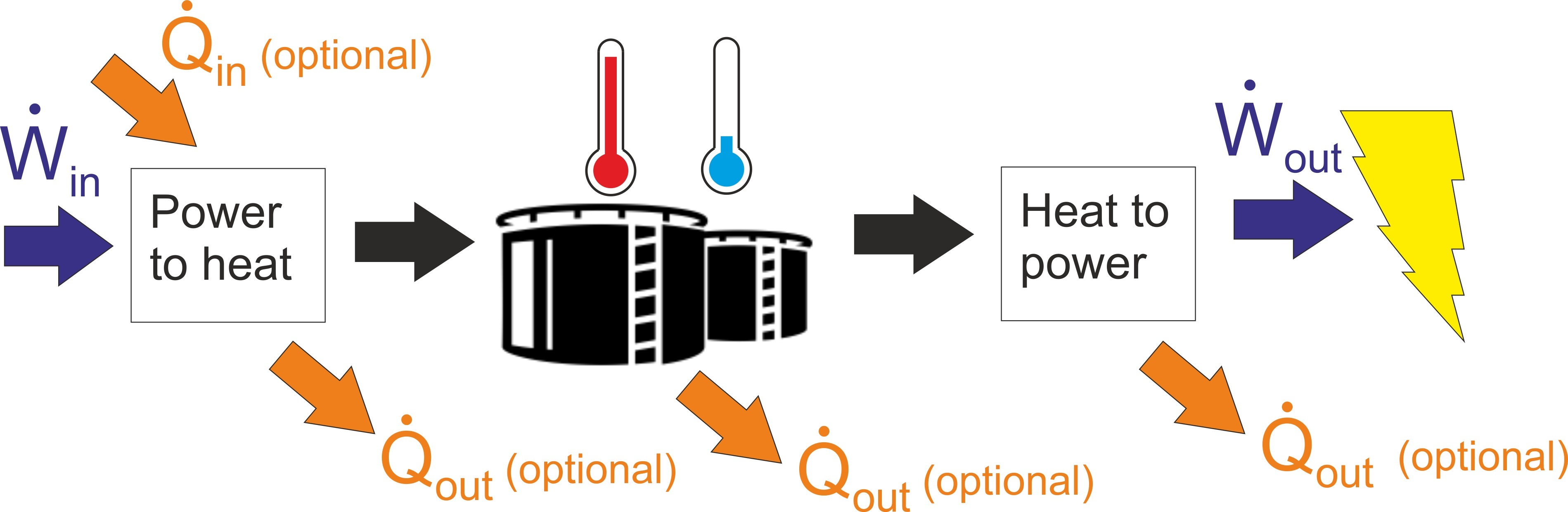
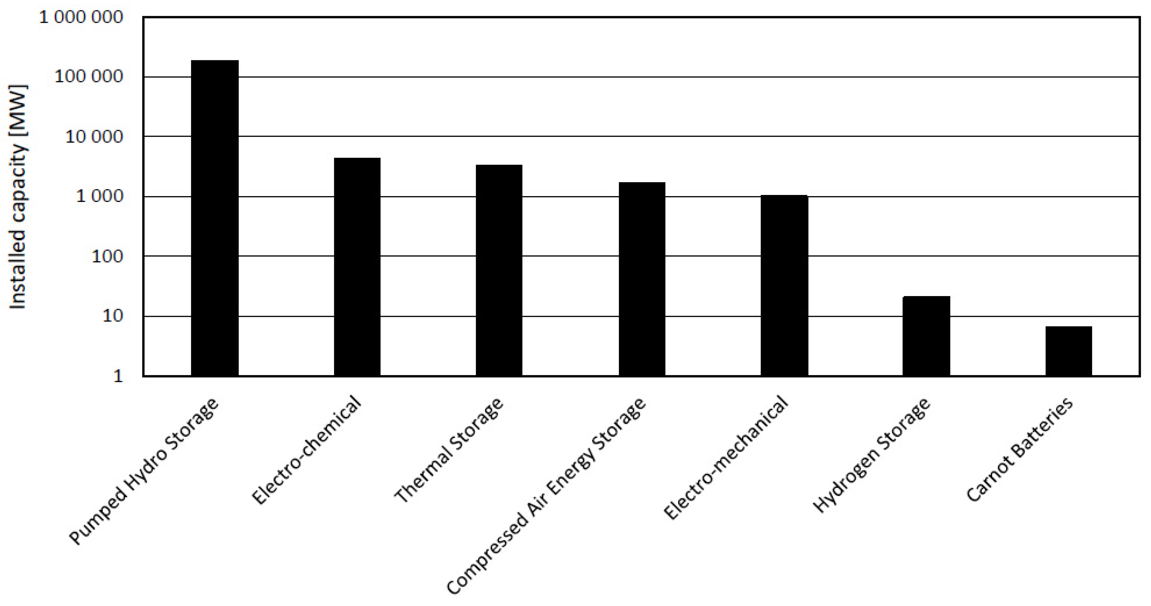
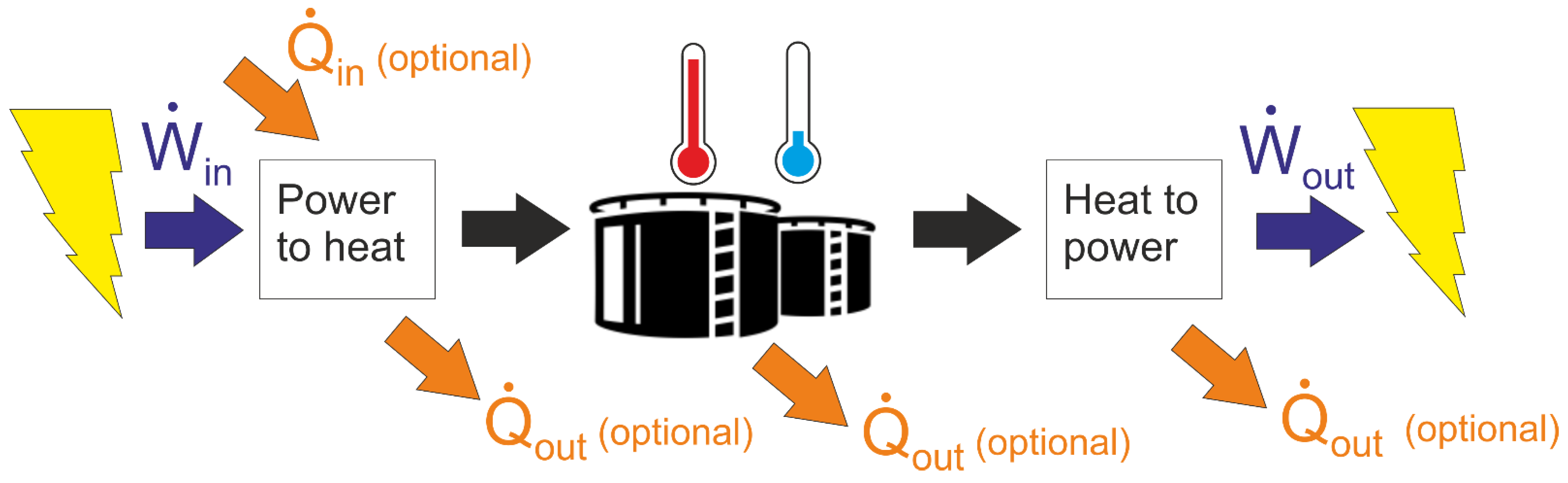
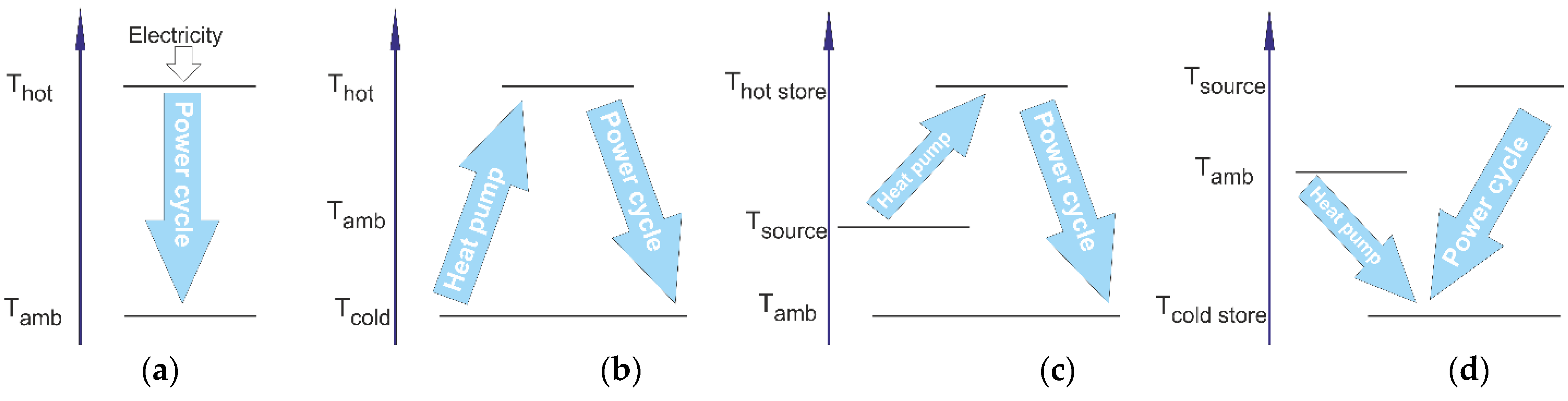
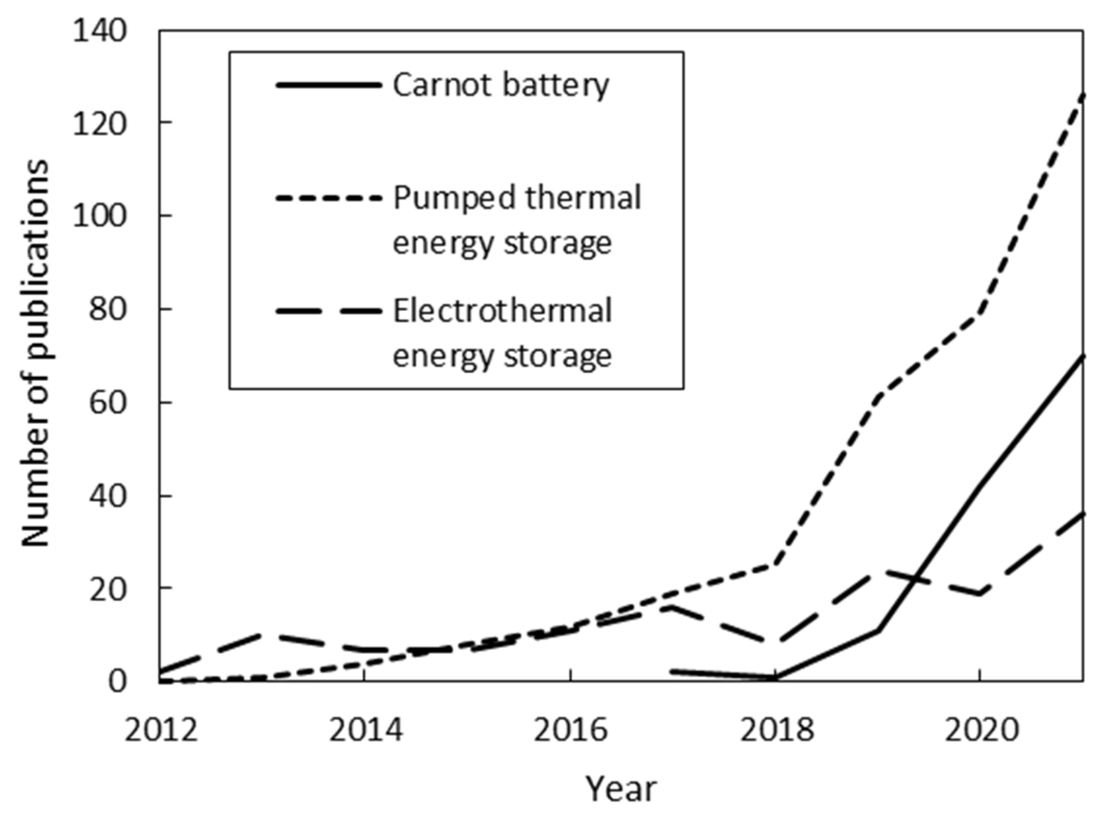
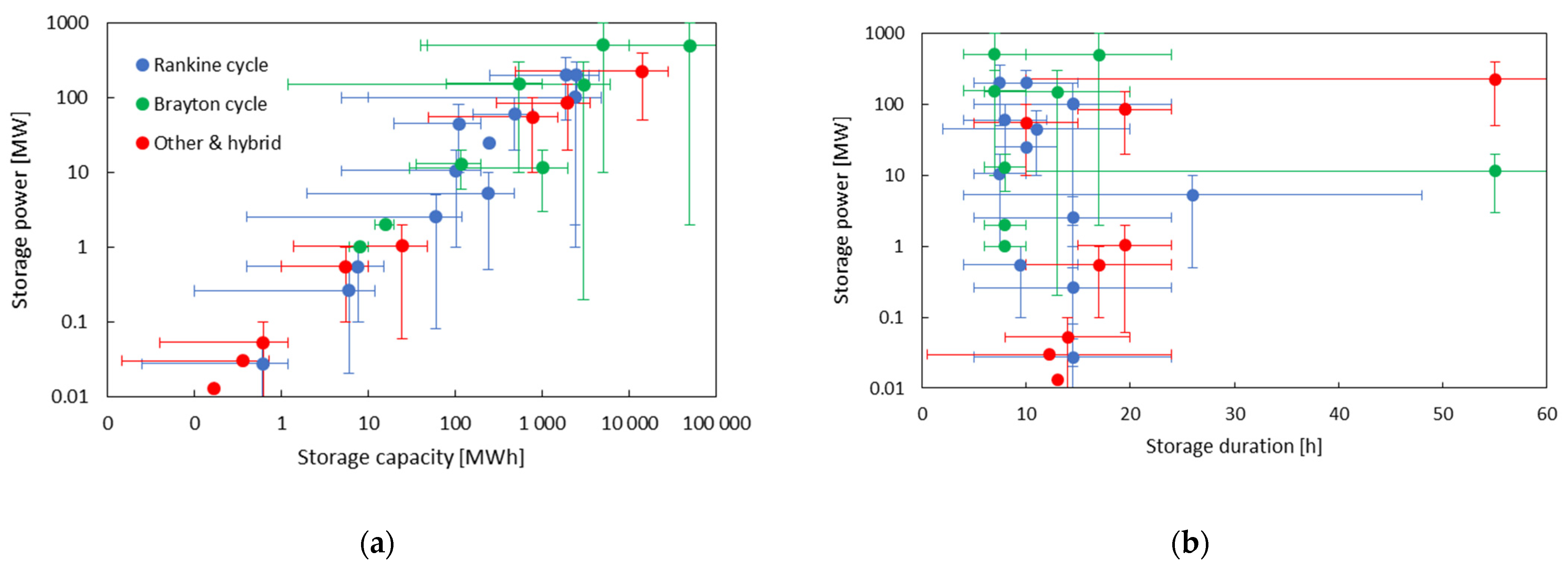
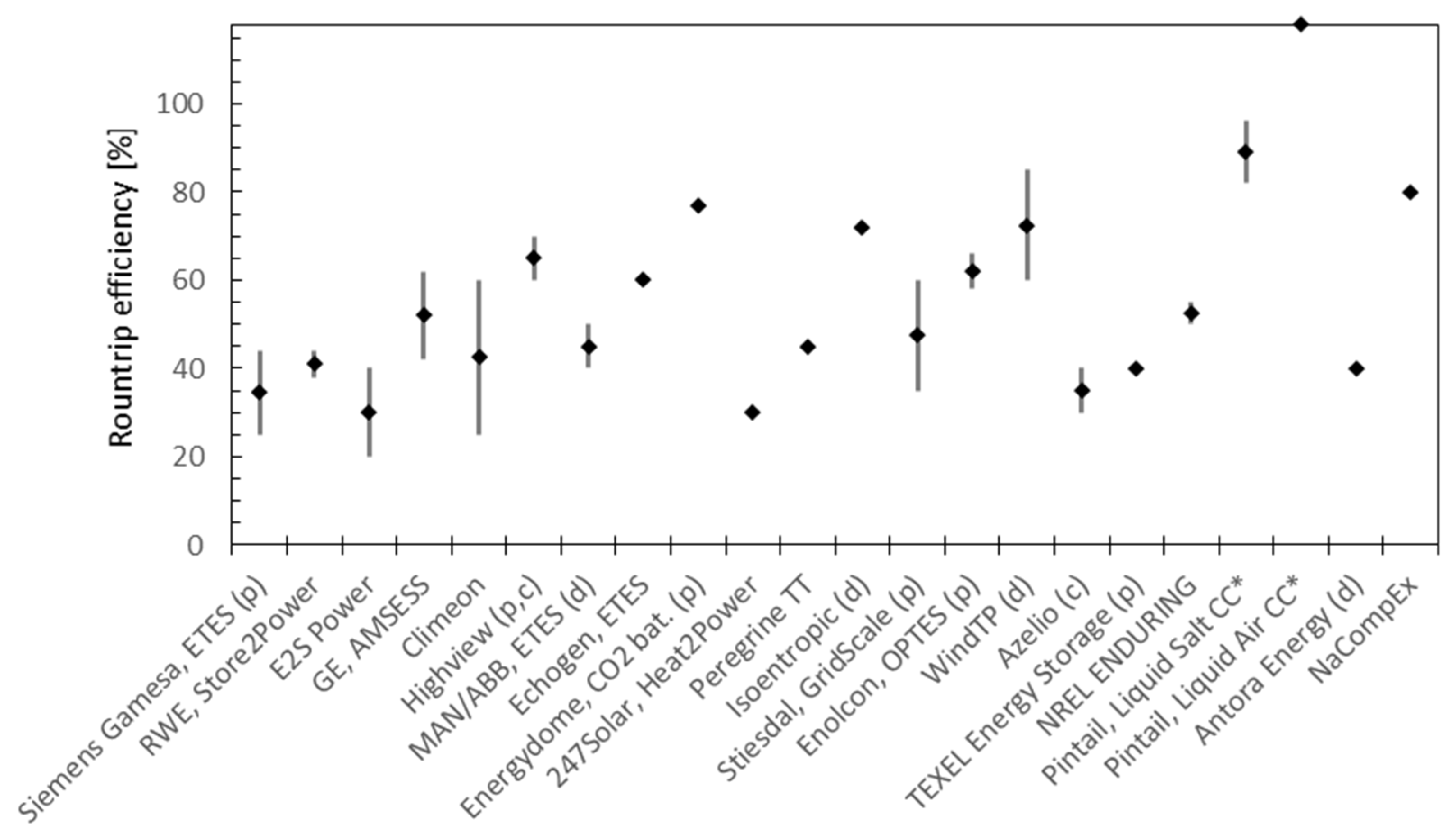
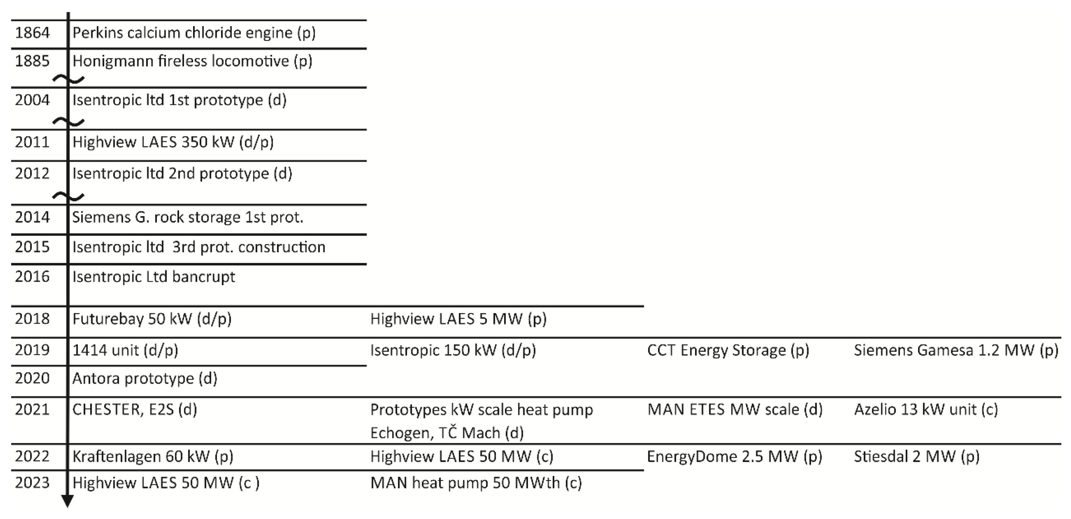
Table 1.
List of commercial development projects in CB using Rankine cycle discharging.
| Company, System | Charging Method | TES | Discharging Method | Power Output | Storage Capacity/Duration | Roundtrip Efficiency | State | Ref. |
|---|---|---|---|---|---|---|---|---|
| Siemens Gamesa, ETES | Resistance heaters to air | Volcanic rock bed~600 °C | steam Rankine cycle | units to 100s MW | 24 h | 25% to >40% | Demo | [32,33,34] |
| RWE, Store2Power | Resistance heaters | molten salt | steam Rankine cycle | 100s MW | hours | ~40% | n.a. | [35] |
| E2S Power | Resistance heaters | Graphite-aluminium alloy at 700 °C | steam Rankine cycle | 1–100s MW | hours | 25–40% | lab proof of concept | [36] |
| Spilling | Steam compression & liquefaction | Saturated water (steam accumulators) | Steam expander (steam engine) | up to MW | hours | n.a. | n.a. | [37,38] |
| GE, AMSESS | CO2 Brayton + el. heating | Molten salt, water tank | Steam cycle with extraction | 20–100 MW | 8 h | 42–62% | Concept | [39] |
| Consortium CHESTER | Heat pump (organic fluid) | PCM and water | ORC | MW scale (8 kW exper.) | hours to days | n.a. | lab proof of concept | [40] |
| Climeon | Heat pump (organic fluid) | water (e.g., district heating system) | ORC | 80 kW to MW | hours | 25–60% | concept with existing ORC | [41] |
| TC Mach | Heat pump (organic fluid) | Stone dust TES | ORC | kW | hours | n.a. | construction of proof of concept | [42] |
| Future Bay | Heat pump (organic fluid) | water (hot) and PCM (cold) | ORC | 10s kW | hours | n.a. | Demo | [43] |
| Highview | Air liquifaction | Liquid air + other TES | Vaporization, expansion turbine | 50–350 MW | about 6 | 60–70% | Pilot, full scale construction | [44,45,46] |
| MAN/ABB, ETES | CO2 heat pump | 120 °C water + cold (ice) storage | CO2 Rankine cycle | several MWe | ~5 h | ~45% | lab demo | [31,47,48,49] |
| Echogen, ETES | CO2 heat pump, fluidized bed heat exchange | Sand (hot) and ice (cold) | CO2 Rankine cycle | 25 MW | 250 MWh | ~60% | design | [50,51,52,53,54] |
| Energydome, CO2 battery | CO2 compression & liquefaction | Liquid CO2 + other TES | Vaporization, expansion turbine | 10–80 MW modules | 20–200 MWh | 77% | Pilot construction | [55,56] |
Table 2.
List of commercial development projects in CB using Brayton cycle discharging.
| Company, System | Charging Method | TES | Discharging Method | Power Output | Storage Capacity/Duration | Roundtrip Efficiency | State | Ref. |
|---|---|---|---|---|---|---|---|---|
| 247Solar, Heat2Power Turbine | Electric resistance heaters | Silica sand | Gas turbine (Brayton cycle) | 200 kWe–100s MW | 6–20 h | 30% | Concept, design | [89,90] |
| 1414Degrees, TESS | Electric resistance heaters | Silicon based alloy, melting temperature 1414 °C | Gas turbine (also steam turbine, Stirling engine, direct heat) | 10 MW-GW | n.a. | n.a. | Demos (done) Planning grid scale pilot | [91] |
| Peregrine Turbine Technologies | Electric resistance heaters | Graphite-aluminium alloy (MGA), 800 °C | CO2 Brayton cycle | 1 MW | 8 MWh | 45% | CO2 turbine/compressor tests | [92] |
| Isoentropic | Heat pump (Brayton cycle -reciprocating devices) | Crushed rock packed bed | Brayton cycle (reciprocating devices) | 2 MW (exper. 150 kW) | 16 MWh | 72% | Demo (bankruptcy) | [93] |
| Malta, Pumped Heat Energy Storage | Heat pump (reverse Brayton cycle) | Molten salt + hydrocarbon antifreeze | Recuperated Brayton cycle | 10–100 MW | 80 MWh–1 GWh | n.a. | Concept, design | [26] |
| Stiesdal, GridScale | Heat pump (reverse Brayton cycle) | Crushed basalt rock packed bed | Brayton cycle | 2 MW–1 GW | 100,000 MWh | 35–60% | Pilot construction | [94] |
| Enolcon, OPTES | Heat pump (reverse Brayton cycle), N2 or Ar | Silica sand packed bed (silica sand, iron based sand, basalt) | Brayton cycle, N2 (or Ar) | ~8 MW | ~80 MWh | 58–66% | Concept, design (Pilot designing/ constructing) | [30] |
| WindTP | Heat pump (reverse Brayton cycle) | Gravel bed, indirect heat transfer | Brayton cycle | 3–20 MW | up to 100 h | up to 85% | component demo | [95] |
Table 3.
List of commercial development projects in CB in the other and hybrid discharging cycle category.
Table 3.
List of commercial development projects in CB in the other and hybrid discharging cycle category.
| Company, System | Charging Method | TES | Discharging Method | Power Output | Storage Capacity/Duration | Roundtrip Efficiency | State | Ref. |
|---|---|---|---|---|---|---|---|---|
| Azelio | Electric resistance heaters | Aluminium based PCM (600 °C) | Stirling engine | 13 kW | 13 h | ~30% | Multiple pilots, production line, commercial | [115] |
| CCT Energy Storage | Electric resistance heaters | Silicon based PCM (1400 °C) | Stirling engine | 5–100 kW | up to 1.2 MWh per module | n.a. | Pilot | [116,117] |
| TEXEL Energy Storage | Electric resistance heaters | Metal hydrides (MH)/metal carbonates | Stirling engine | 30 kW | 15–720 kWh | 40% | commercial installation effort | [118] |
| Kraftlagenn München | Electric resistance heaters/waste heat | Ceramic system (1000 °C) | Stirling engine and ORC | 60 kW (demo) | 1.4 MWhth (demo) | n.a. | demo | [119] |
| NREL ENDURING LDES (GE, PEI, Allied) | Electric resistance heaters | Fluidized packed bed with solid materials (1100 °C) | Combined Brayton and Rankine cycle | 50–400 MW | 10–100 h | 50–55% | Components prototypes, demo preparation | [120] |
| Pintail Power, Liquid Salt Combined Cycle | Electric resistance heaters | molten salt | Combustion combined cycle integration | from dozens MW | 24 h | 82–96% (+ fuel) | Patented concepts | [121] |
| Pintail Power, Liquid Air Combined Cycle | Compressor for air liquefaction | liquid air | Combustion combined cycle integration | from dozens MW | 24 h | 118% (+ fuel) | Patented concepts | [122] |
| Antora Energy | Electric resistance heaters | Graphite blocks (1500 °C) | Thermophotovoltaic cell | 0.1–1 MW | 10 MWhe | 40% | Proof of concept | [123] |
| NaCompEx | Compresed heat followed by desorption | NaOH-H2O solutions via concentration difference | Expansion followed by absorption | 10–100 MW | 60 kWh/m3 storage | 80% | Concept, design | [124,125] |
Table 4.
Overview of the TES systems for Carnot battery applications.
| Company, System | TES Type (Temperature Limit) | Thermal Capacity | State | Ref. |
|---|---|---|---|---|
| EnergyNest | High temperature concrete modules (up to 380 °C) | Scalable to hundreds of MWh | Pilot plant, preparing commercial project | [150] |
| Storworks power, BolderBloc | High temperature concrete modules (up to 600 °C) | from 30 MWh | 200 kWh demo, construction of 10 MWh | [151] |
| Kraftblock | High temperature concrete granules (up to 1300 °C) | Scalable | Pilot industrial applications | [152] |
| Magaldi Green Energy | Silica sand fluidized bed (up to 1000 °C) | 5 to 100 MWh | full size demonstrator | [153] |
| Dürr & Kraftanlagen | Ceramic blocks with gas heat exchange | MWh to GWh | Demonstrator as CB | [154] |
| Carboclean | Ceramic blocks with direct heating (above 1000 °C) | up to 1 GWh | Laboratory proof of concept | [155] |
| Joule Hive (Electrified Thermal Solutions) | Ceramic firebricks (up to 1700 °C) | n.a. | n.a. | [156] |
| BrenmillerEnergy | Rock bed | 6–750 MWh | Pilot applications | [157] |
| Lumenion | Steel rods (up to 650 °C) | up to 500 MWh | Pilot applications | [158] |
| Kyoto, Heatcube | Molten salt (525 °C produced steam) | 4–100 MWh | Pilot applications, commercial order | [159] |
| Hyme | Molten hydroxide up to 700 °C | Scalable | Patents, laboratory experiments | [160] |
| SaltX | Thermochemical | from 10 MWh | Pilot applications | [161] |
Publisher’s Note: MDPI stays neutral with regard to jurisdictional claims in published maps and institutional affiliations. |
© 2022 by the authors. Licensee MDPI, Basel, Switzerland. This article is an open access article distributed under the terms and conditions of the Creative Commons Attribution (CC BY) license (https://creativecommons.org/licenses/by/4.0/).
Share and Cite
MDPI and ACS Style
Novotny, V.; Basta, V.; Smola, P.; Spale, J. Review of Carnot Battery Technology Commercial Development. Energies 2022, 15, 647. https://0-doi-org.brum.beds.ac.uk/10.3390/en15020647
AMA Style
Novotny V, Basta V, Smola P, Spale J. Review of Carnot Battery Technology Commercial Development. Energies. 2022; 15(2):647. https://0-doi-org.brum.beds.ac.uk/10.3390/en15020647
Chicago/Turabian StyleNovotny, Vaclav, Vit Basta, Petr Smola, and Jan Spale. 2022. "Review of Carnot Battery Technology Commercial Development" Energies 15, no. 2: 647. https://0-doi-org.brum.beds.ac.uk/10.3390/en15020647
Note that from the first issue of 2016, this journal uses article numbers instead of page numbers. See further details here.