
Wireless Power Transfer—A Review

Department of Marine Electronics, Faculty of Electrical Engineering, Gdynia Maritime University, Morska 83, 81-225 Gdynia, Poland
*
Author to whom correspondence should be addressed.
Energies 2022, 15(19), 7236; https://0-doi-org.brum.beds.ac.uk/10.3390/en15197236
Submission received: 5 September 2022
/
Revised: 23 September 2022
/
Accepted: 27 September 2022
/
Published: 1 October 2022
(This article belongs to the Section F3: Power Electronics)
Abstract
:This paper presents the current state of knowledge in the field of wireless power transfer. The concept of such a transfer and the basic methods of its implementation are described, together with block diagrams of the necessary devices. The technologies of electrical power transfer over short and long distances are characterized. The most popular electrical power transfer technology based on the phenomenon of electromagnetic induction is discussed in great detail. The analysis of the influences of such factors as the coupling factor, the shape of the coils, the type of ferromagnetic material from which the core of the coils is made, and the mutual position of the transmitting and receiving coils are analyzed on the properties of the wireless power transfer system. The advantages and disadvantages of the used technologies are shown. Furthermore, a wireless power transfer system is presented for charging the batteries of electric vehicles. The standards of wireless power transfer are also presented, and development trends are outlined.
1. Introduction
In recent years, significant technological progress has been observed in the production of portable electronic and power electronic devices for various purposes. They are characterized by smaller sizes and higher energy efficiency, as well as higher values of transformed power [1,2].
Despite the high technological advancement of the mentioned portable devices, a problem of replenishment of energy in the supply battery has been observed. Currently, electronic devices such as telephones, tablets, and computers can operate without recharging for up to several dozen hours [3]. However, the mentioned portable devices need frequent recharging or the purchase of other batteries. This generates additional costs and it is not conducive to the world’s environmental protection policy [4,5]. An interesting solution to this problem is wireless power transfer.
A pioneer in this area (power transfer by electromagnetic flux density) was a Serbian scientist, Nikola Tesla [6], who in 1891, designed the Tesla coil, which was a device with a length of about 40 m. The Tesla coil was powered by a 300 kW signal at a frequency of 150 kHz and could transmit electricity up to 3 km without using a wire [7]. As a next step, the Serbian scientist planned to build a system for the universal wireless transmission of electricity using transmission and reception towers. The Tesla Experimental Transmission Tower was built on Long Island (known as the Wardenclyffe Tower). However, due to a lack of funds for further investigations, the Tesla project was closed down in 1906 and the tower was demolished in 1917 [8]. Subsequent experiments in the field of wireless power transfer were also carried out by John Schuder (1961) [9], William Brown (1964) [10], and Peter Glaser (1968) [11].
However, it was not until about 2007 that more attention was paid to these systems, when a group of scientists from MIT designed a functioning model of the wireless power transfer (WPT) system, which enabled the transmission of electricity necessary to ignite a 60 W bulb at a distance of 2 m [6,12].
Wireless power transmission systems, besides their applications for charging the batteries of the previously mentioned consumer electronic devices, are also increasingly used in the automotive industry for charging electric vehicle batteries [13,14,15], for mining in places where it is not possible to use conventional wired power [16], and in medicine [17,18,19,20].
The aim of this paper is to analyze the properties of wireless power transfer systems with a particular emphasis on inductive wireless power transfer. This paper presents the general characteristics of WPT, discusses the advantages and disadvantages of these systems, and analyzes a selected area of industry in which this technology is beginning to be developed more widely. Section 2 presents the classification of available WPT technologies and describes the principle of operation of each of them. Section 3 describes the advantages and disadvantages of wireless power transfer, Section 4 presents the most commonly used standard of WPT for charging small mobile devices, and Section 5 describes an example of the use of WTP systems in the industry.
2. Classification of Wireless Power Transfer Systems
Wireless power transfer (WPT) systems, also known as cordless power transfer or wireless power charging [7], enable the transmission of electricity between the power source and the load without the use of physical connections in the form of cables [7,21,22,23,24].
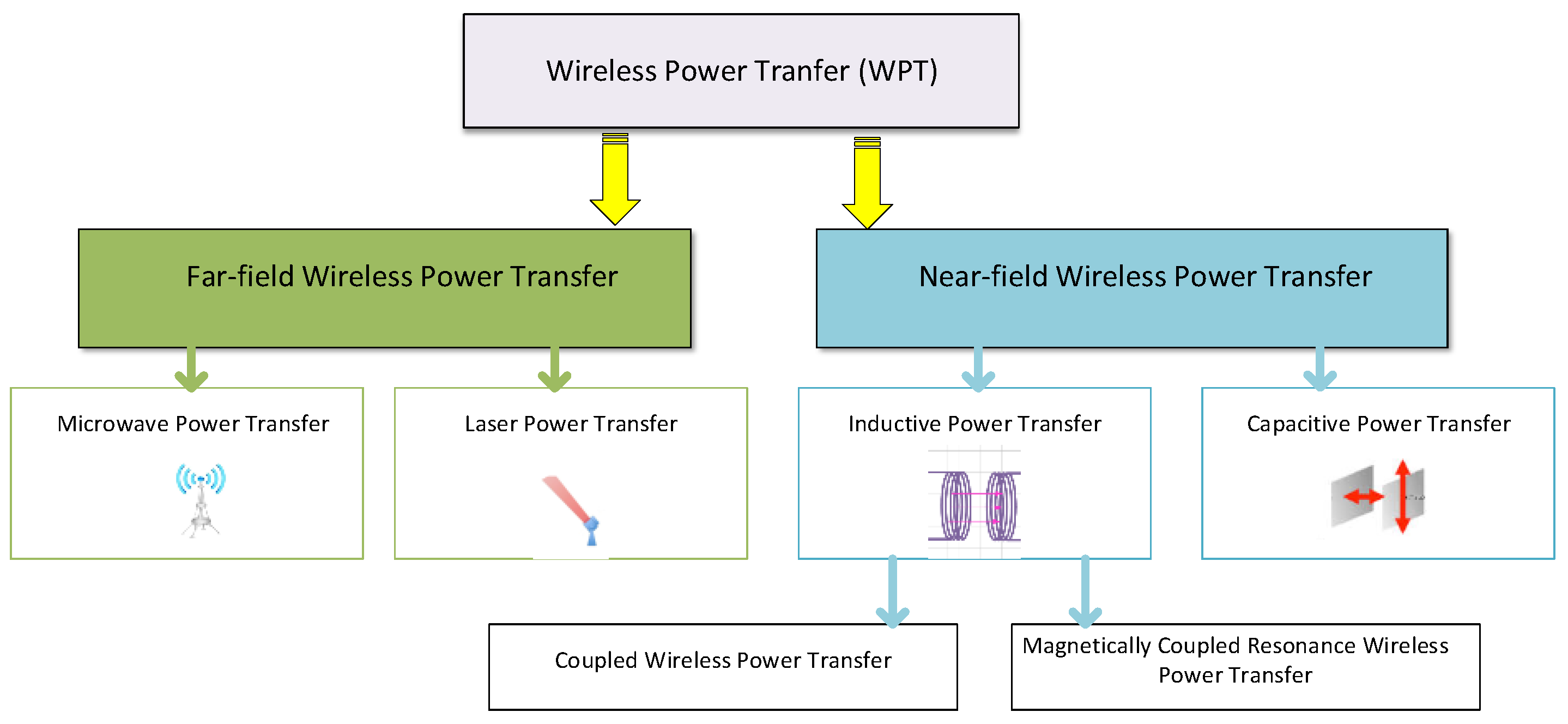
Wireless power transfer (WPT) is typically divided into two categories due to the mechanisms of energy transmission [25,26,27]:
- -
- Far-field power transfer, also known as the radiative method;
- -
- Near-field power transfer, also known as the non-radiative method.
A detailed classification of wireless power transfer systems is shown in Figure 1.
As shown in Figure 1, far-field wireless power transfer systems are divided into systems using microwaves to transmit energy, called microwave power transfer (MPT), and those using laser technology, called laser power transfer (LPT). In turn, near-field wireless power transfer systems also are divided into two categories: inductive power transfer (IPT), where energy is transmitted using a magnetic field, and capacitive power transfer (CPT), where energy is transferred using an electric field. Additionally, the transmission of energy using IPT can be realized with one of two technologies: coupled wireless power transfer (CWPT), or magnetically coupled resonance wireless power transfer (MCRWPT). Section 2.1 presents a brief description of far-field wireless power transfer technology, including MPT and LPT, then Section 2.2 describes the near-field wireless transfer technology in greater detail, including IPT and CPT.
2.1. Far-Field Wireless Power Transfer
Far-field wireless power transfer uses an electromagnetic wave in the form of a radio frequency signal for energy transfer. The transmitter then radiates energy using the electric field of the electromagnetic wave. As mentioned earlier, this type of wireless energy transfer is divided into two groups [25]: microwave power transfer (MPT) and laser power transfer (LPT), which are discussed in greater detail in Section 2.1.1 and Section 2.1.2.
2.1.1. Microwave Power Transfer
MPT is a type of wireless transmission of energy carried out by electromagnetic radiation with the use of microwaves. This technology is widely used in the aviation industry to supply, for example, unmanned ships. The principle of operation of this solution is based on the use of microwave devices for radiating a signal in the form of a radio wave through an appropriate antenna. In the receiver, which is also an antenna, the energy stored in the electric field of the wave is transferred to the load. A significant advantage of this type of transmission is the high value of the transmitted power, very good adaptation to the environment, and great flexibility in transmitting and receiving signals. Due to these factors, this type of energy transmission is used when there is a need to supply devices located at long distances apart and operating in different weather conditions [25,28]. However, a significant limitation in the use of this technology is the very low transmission efficiency, not exceeding 10% [25,28], and the need to use very large transmitters (antennas). This solution is also very expensive.
2.1.2. Laser Power Transfer
Since large-sized antennas are required for energy transmission, increasing attention is paid to energy transmission by means of a laser beam. This method of energy transmission uses highly concentrated laser light directed at the energy receiver to obtain the highest possible transmission efficiency over very long distances. In this type of solution, the transmitter of the wireless power transmission system converts electric energy from the source (e.g., a battery) to a monochromatic light beam using a laser [29,30]. In turn, using a complex optics system, this beam is directed and transmitted to the receiver, which is usually a set of photovoltaic panels placed on satellites. Then, in the receiver adapted to the parameters of the beam, the energy of the laser radiation is converted back to electric energy, which is used to charge the batteries on the satellites or on the motors installed in that location [30]. The essential component of these systems, similar to MPS, is the rectifier module, which should be characterized by a high value of efficiency. Typically, the rectifier module induces power loss, lowering the efficiency by 10% [31]. The high-efficiency rectifier has the functions of stabilizing and amplifying the driving current, thereby minimizing the losses associated with its circuit in a process widely described in [32,33]. The disadvantage of such a solution compared with microwave energy transmission is the need for the receiver to use complex tracking and monitoring systems, which are required to precisely transmit the laser beam to the receiver [25] since laser radiation can be dangerous for people and the environment.
Compared with microwave energy transmission, the laser beam is also more susceptible to atmospheric absorption and scattering by clouds, rain, snow, and fog [25,33]. However, the method of wireless transmission of energy using a laser has become so attractive that under the program (SPRINT) of the United Kingdom Space Research and Innovation Network for Technology that the British company Space Power, in cooperation with scientists from the University of Surrey, is planning to launch a prototype of an LPT device, which will be used to illuminate satellites orbiting close to the Earth during an eclipse. The commercialization of the proposed solution is planned for 2025 [25,34].
2.2. Near-Field Power Transfer
A typical system for wireless transmission of energy consists of a transmitter and a receiver. The energy within this transmission system can be transmitted via a magnetic or electric field [23,24,35,36]. In this case, one of the two techniques of electric energy transmission is used, the inductive (IPT) or the capacitive (CPT) technique [25]. In the case of energy transmission using a magnetic field, the transmitter and the receiver are coils. On the other hand, the transmission of energy using an electric field is possible with the use of two flat capacitors: a transmitter and a receiver [37].
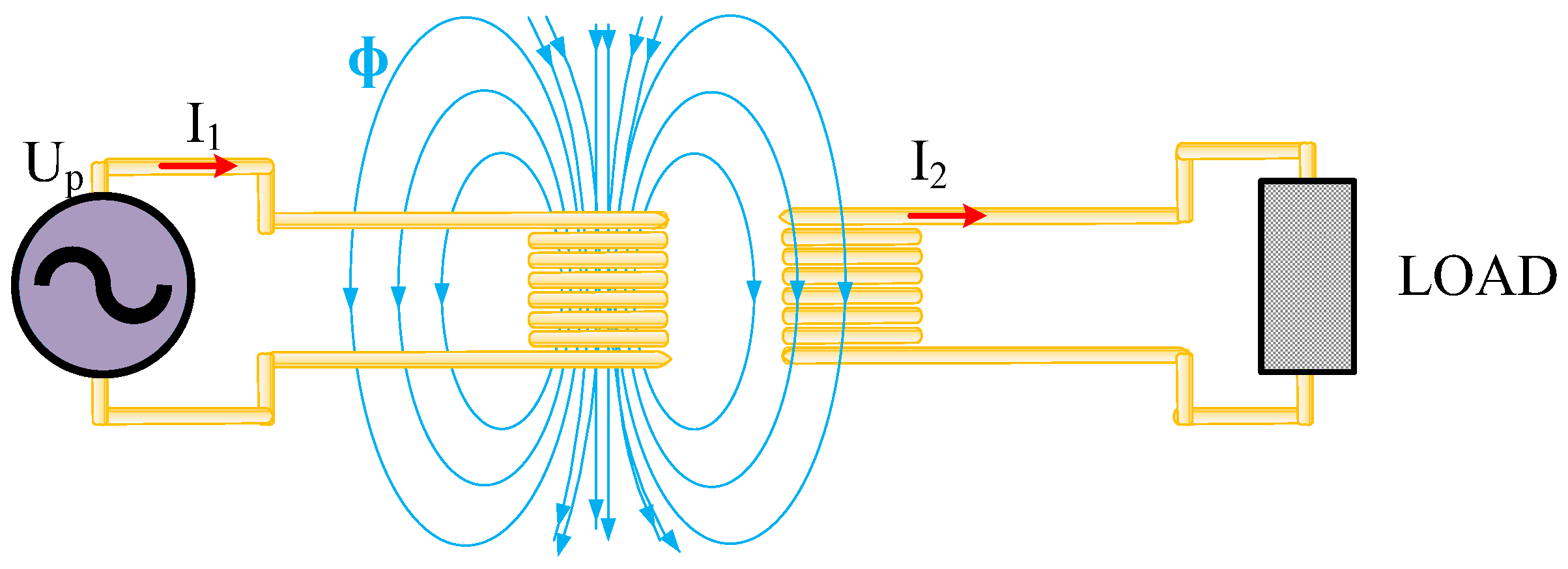
Near-field power transfer is the most frequently described due to the great interest in its development and its widespread use in various industries (such as biomedicine, implantology, portable devices, underwater robots, underwater sensors, and electric vehicles). Additionally, it is also the most developed wireless power transfer technology [16,21,25,38]. Figure 2 shows the principle of electric energy transmission using the induction method. This method is the more frequently used method under the category of near-field IPT.
The principle of electric energy transmission by the induction method is based on the principle of operation of an air transformer. When an alternating voltage source Up with amplitude U0 and frequency f is connected to the terminals of the primary winding of the transformer, the current flows through the primary winding N1. The result is that it will create a time-varying magnetic flux that influences the secondary winding N2. Due to the phenomenon of electromagnetic induction, which is the result of the formation of an electromotive force in the secondary winding, the current will also flow. In a case where the lines of the force of the magnetic field with induction B are perpendicular to the surface S through which the magnetic flux passes, and additionally the magnetic field is homogeneous, then the expression for magnetic flux is expressed by [39]:
According to Faraday’s law, the value of the induced electromotive force ɛ is equal to the product of the number of turns N2 of the secondary winding and the time derivative of the magnetic field flux ϕ. Taking into account dependence (1), the electromotive force is expressed by [39]:
Assuming that the losses in the winding are negligible, it can also be assumed that the voltages on N1 and N2 windings will be equal to the electromotive forces. Then, the effective values of the voltage on the windings of the n-th winding of the transformer can be determined from the formula [39]
where Nn denotes the n-th winding number, k is the coupled coefficient, and Bm the amplitude of magnetic flux density.
2.2.1. Inductive Power Transfer
IPT technology is based on the concept of the laws of Amper and Faraday. The method of power transfer using IPT technology was demonstrated for the first time in 1898 by Nicola Tesla.
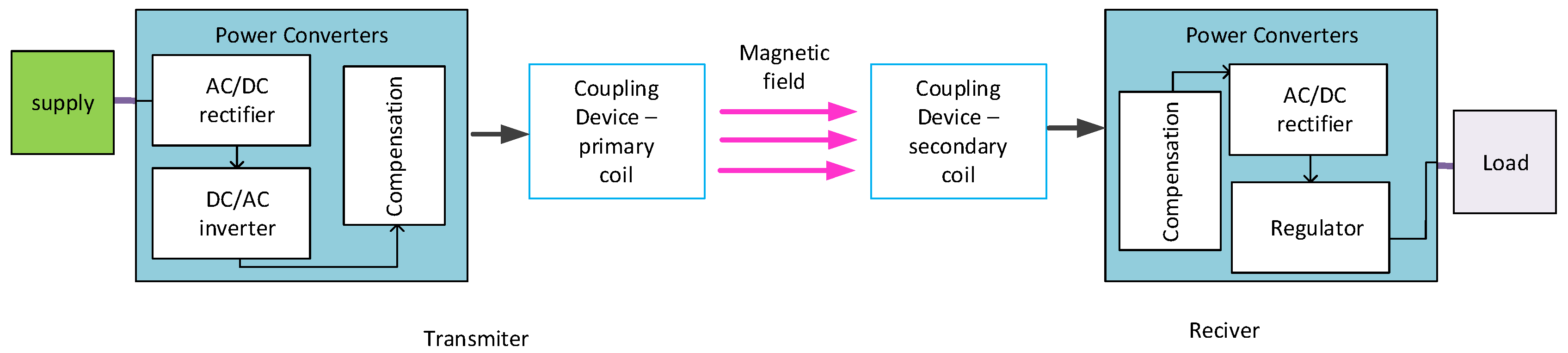
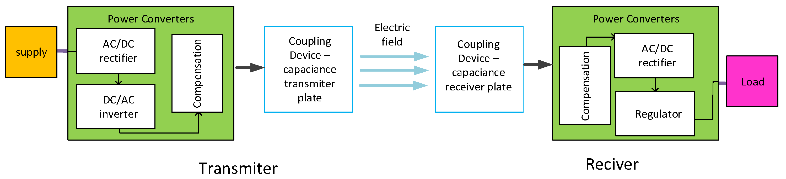
As mentioned earlier, this technology can be divided into two groups: inductive coupled wireless power transfer (IWPT) and magnetically coupled resonance wireless power transfer (MCR WPT) [7,21,22,35]. A typical system used in both considered topologies is shown in Figure 3.
In the system presented in Figure 3, on the transmitter side, there are blocks representing a rectifier that converts the alternating voltage from an external power source, that is, the power grid, into a direct voltage of the required value, which depends on the application. In the transmitter block, there is also a DC/AC inverter used to change the DC voltage to the alternating voltage, and the last element of the transmitter system is a coil. The receiver circuit consists of a receiving coil, an AC/DC rectifier for converting the alternating voltage to the direct voltage, and a regulator to stabilize the voltage at the receiver output. Since the value of the coupling coefficient between them decreases with an increase in the distance between the transmitter and the receiver, it causes an increase in voltage drops due to leakage inductance and a reduction in energy transfer.
To eliminate this problem, additional compensation blocks are used—creating a resonant circuit [40,41,42]. These blocks usually consist of capacitors connected in various configurations to the receiver and the transmitter. With the application of such a solution, it is possible to obtain a reduction in the system impedance in systems characterized by a higher inductance of leakage than the mutual inductance. The topologies and properties of these systems were extensively described in the papers [43,44,45,46].
Inductive Coupled Wireless Power Transfer
Inductive coupled wireless power transfer technology is based on the transmission of energy by means of a magnetic field of transmitting and receiving coils coupled together at a short distance from each other. The mechanism of energy transfer is identical to the mentioned principle of operation of an air transformer [22,35]. The operating frequency range of this solution is kilohertz, and the typical distance between the transmitter and receiver does not exceed 40 mm. Additionally, this technology enables the transmission of energy from single watts to kilowatts [22].
The papers [16,47,48] demonstrated that an increase in the distance between the transmitter and the receiver from 20 mm to 100 mm reduces the value of the coils’ coupling coefficient from 0.6 to 0.1 and the energy transmission efficiency from 80% to about 40%. The number of turns, as well as the shape and size of the coil, are also important for the value of this coefficient and the transmission efficiency.
An advantage of IWPT is the fact that it is a simple method of energy transmission of high efficiency compared with other systems, and has a low operating frequency, which ensures the safety of energy transmission. On the other hand, the significant disadvantages of this energy transmission technology are the short distance of energy transmission, the electromagnetic coupling coefficient, the low value of mutual inductance, and significant heating of the considered systems as a result of losses in the windings. Additionally, increasing the distance between the coils lowers the efficiency of energy transmission. Its efficiency is also influenced by the position of the coils in relation to each other. It is important to adjust the position as well as the distance between the transmitter and receiver [16].
Magnetically Coupled Resonance Wireless Power Transfer
The principle of operation of magnetically coupled resonance wireless power transfer technology, as in the case of IWPT, is also based on the principle of an air transformer, but here, the resonance frequency at which both coils operate is important. The frequency of operation in this technology ranges from a few kilohertz to tens of megahertz. Energy can be transmitted over a distance of several meters regardless of the prevailing weather conditions. A significant advantage of this technology is that there is no need to adjust the positions of the transmitter and the receiver in relation to one another. It is enough for the receiver to be within the range of the transmitter to start energy transfer.
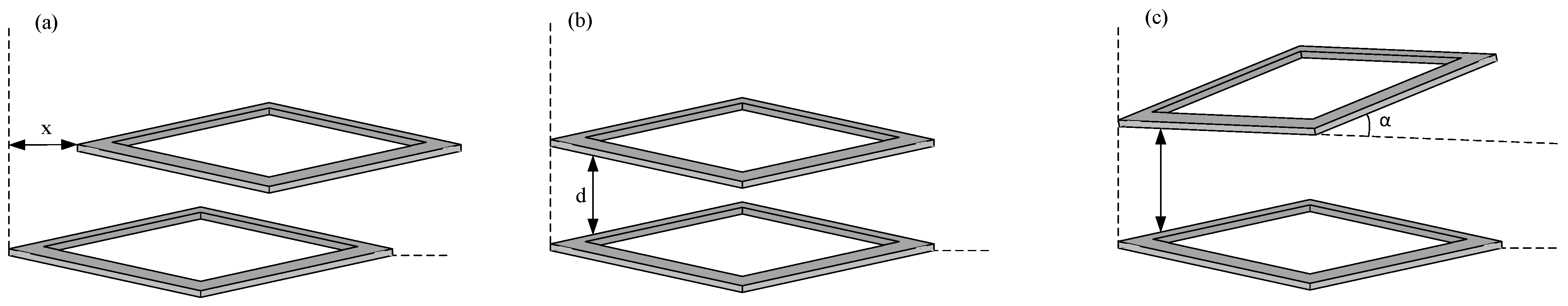
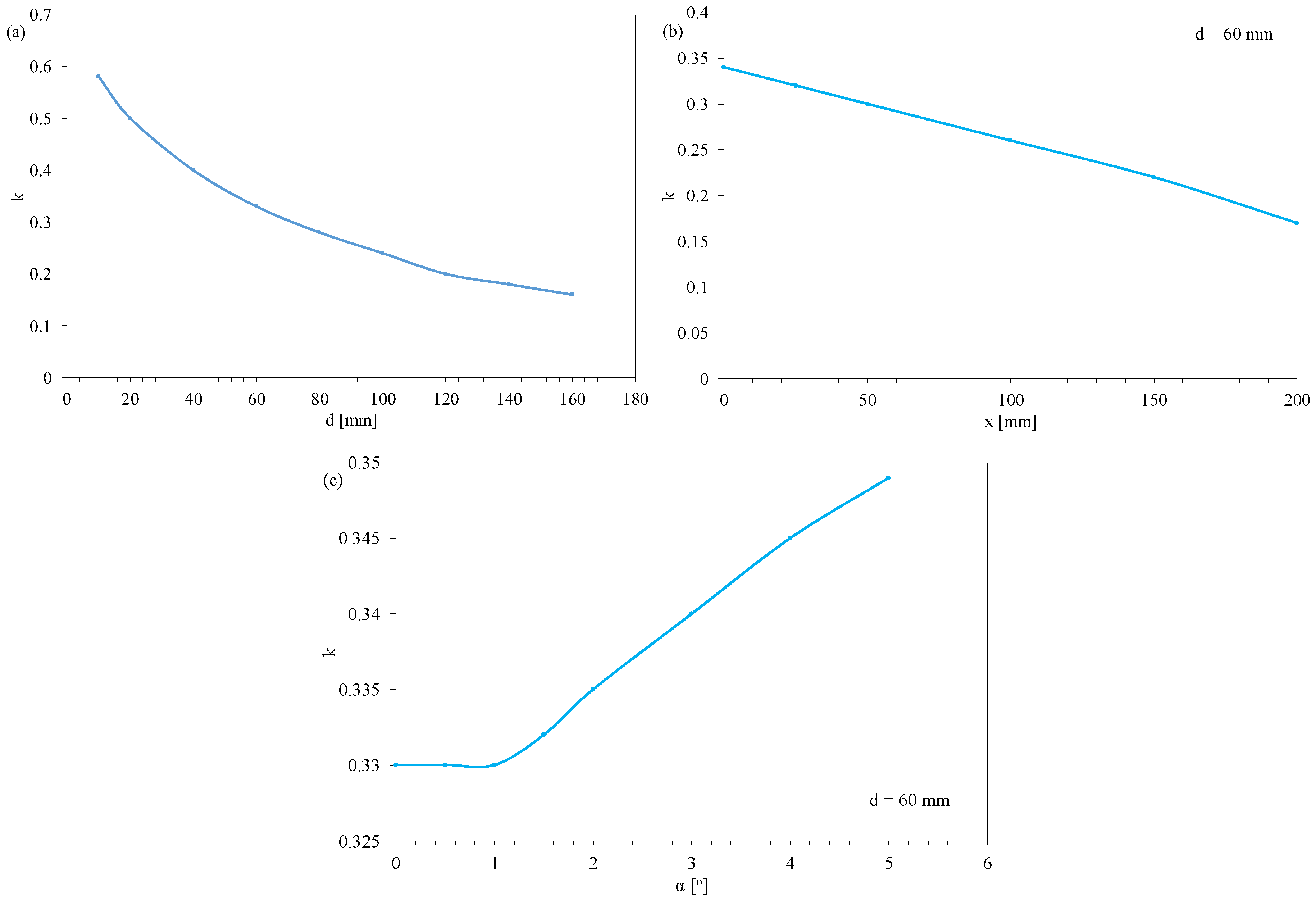
As presented in [47], the change of position between the transmitting and receiving coils of wireless energy transmission systems significantly influences the coupling coefficient between these coils, which, in turn, significantly affects the efficiency of energy transmission. Figure 3 shows different configurations for transmitter and receiver arrangement. The authors of the cited paper carried out investigations for coils with a rectangular cross-section. The inner window of the considered coils has a length of 498 mm, width of 10.4 mm, and thickness of 20.2 mm. Each coil contains 12 turns, and the self-inductance of a single coil is 212 µH. The results of investigations into the influence of the distance d, the angle of inclination α, and the position of the receiver in relation to the transmitter on the x-axis, obtained by the authors, on the value of the coupling coefficient k, are shown in Figure 4.
As can be seen (Figure 5), the value of the coupling coefficient between the transmitting and receiving coils decreases with an increase in the distance when the distance is changed vertically and horizontally. It can be observed that an increase in the vertical distance from 15 mm to 160 mm causes an almost threefold reduction in the value of the coupling coefficient. Additionally, increasing the horizontal distance between the coils by approximately 200 mm reduces the coupling coefficient value by approximately 50%. The smallest effect of a change in the position of the receiving coil in relation to the transmitting coil on the value of the coupling coefficient k is observed when changing the inclination of the receiving coil. Changing the slope of the receiving coil from 1 to 5 °C increases the coupling factor by as little as 6%.
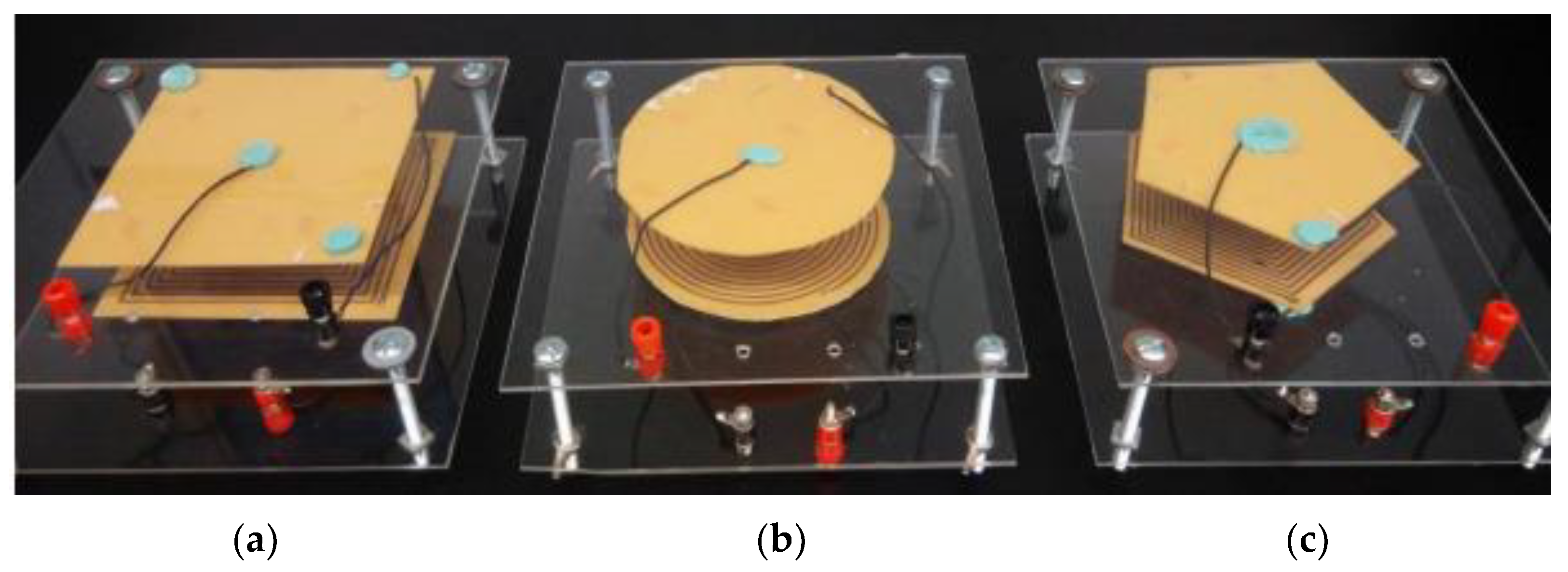
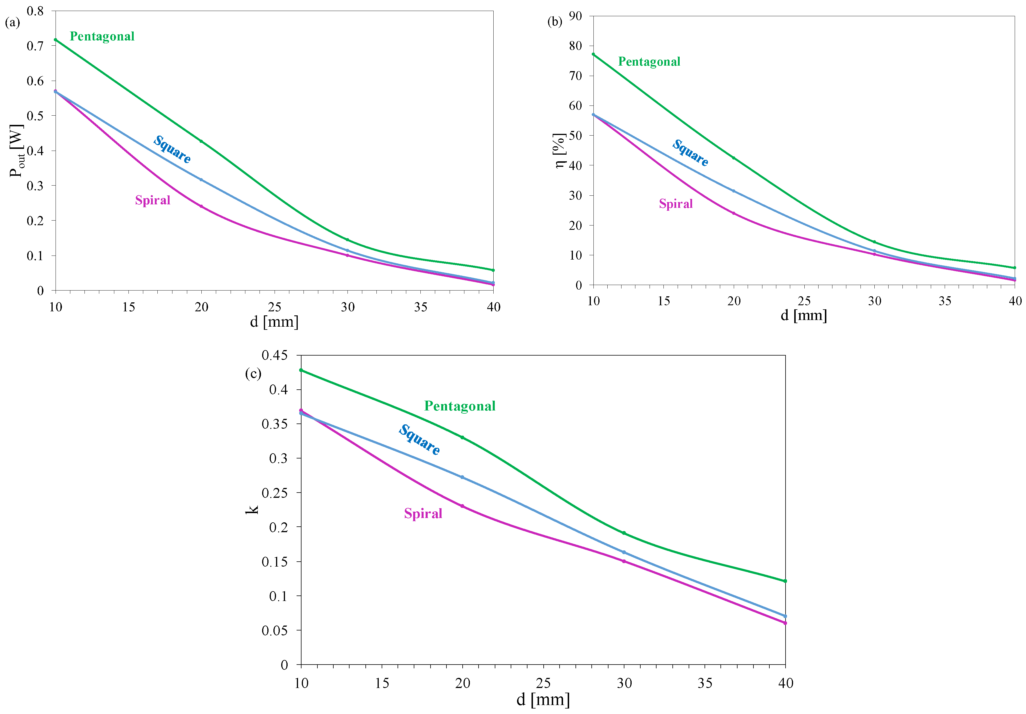
On the other hand, the paper [48] presents the influence of the shape of the coils used for wireless power transmission on such IPT parameters as the output power Pout, the efficiency of power transfer η, and the coupling coefficient k. The oval, square, and pentagonal shapes of the receiving coil were considered. The examples of the transmitter and the receiver coils presented in [48] are shown in Figure 6. The investigated coils have similar sizes, i.e., their surface areas are about 110–120 mm2, and contain a similar number of turns on both windings, i.e., 15 turns for the spiral coil and 14 turns for the coils with the pentagonal and square shapes. The results obtained by the authors of the cited paper are presented in Figure 7.
Figure 7 shows the dependence of the output power Pout (Figure 7a), energy transmission efficiency η (Figure 7b), and the coupling coefficient k (Figure 7c) on the distance between the coils for the oval, square, and pentagonal shapes, respectively.
From the characteristics presented in Figure 7, it can be seen that the values of the three considered parameters decrease with an increase in the distance, even by several times, representing a phenomenon also mentioned in [16,47]. Moreover, it can be observed that the values of these parameters are significantly influenced by the shape of the coil. Interestingly, the lowest value of electric energy transmission efficiency was obtained for oval coils when the distance between them did not exceed 30 mm, while the highest value for this parameter was obtained for pentagonal-shaped coils. In the range of d changes from 10 mm to 20 mm, this value was even 30% higher than the energy transmission efficiency obtained for the other considered coils. It can also be observed that the highest values of the coupling coefficient were obtained for pentagonal-shaped coils over the entire range of variations in the distance between the considered coils. The use of pentagonal coils allowed for increasing the value of the coupling coefficient between the coils by up to 30%.
As shown in the literature [49], the goodness Q of the coils of both the transmitter and the receiver is a very important parameter in wireless power transfer using the phenomenon of magnetic induction. This factor characterizes losses from the coil and depends primarily on the size of the coil, the thickness of the wire, and the material from which it is made—a copper wire, aluminum, etc. The default value for this parameter oscillates around Q = 100. A higher value for this parameter results in better properties of the WPT system.
On the other hand, the paper [50] investigated the influence of the Q factor on the power transmitted between the transmitting and receiving coils and on the efficiency of energy transmission. The results are shown in Figure 8.
From the dependences presented in Figure 8, it can be seen that the power received by the receiving coil increases with an increase in factor Q. Increasing this factor from 20 to 110 causes more than a threefold increase in power. In turn, from the dependence on energy transmission efficiency (Figure 8b), it can be seen that an increase in Q from 20 to 110 causes a reduction in the efficiency of electricity transmission by approximately 10%. It is worth noting that the applied system allowed a very high efficiency of electricity transmission—almost 90%—to be achieved.
The paper [51] described the influence of the ferromagnetic material and the frequency of the transmitted voltage on the efficiency of wireless power transfer. In the cited paper, four ferromagnetic cores were analyzed, made of such materials as ferrite, sendust, iron dust, and NiZn alloy. These had external diameters of 36, 27, 27, and 31 mm, internal diameters of 23, 14.35, 14.5, and 19, and thicknesses of 10, 12, 14.6, and 13 mm, respectively. The investigations were carried out in the frequency range from 10 to 140 kHz.
Figure 9 shows the dependence of the efficiency of energy transmission for the mentioned materials on the frequency [51].
As shown in Figure 9, the frequency does not significantly influence the efficiency of energy transmission with the use of irondust material. However, the use of this material produces a value for the considered parameter up to 10 times lower than in the case of the ferrite material and four times lower than in the case of the NiZn material in the range of higher-frequency values. The highest efficiency was obtained with the use of the ferrite material. An increase in the frequency from 10 to 140 kHz resulted in an almost twofold increase in the efficiency of energy transmission when using the core made of ferrite material for the construction of the transmitter and the receiver.
2.2.2. Capacitive Power Transfer
Capacitive power transfer technology uses capacitive coupling between the transmitter and the receiver, which are electrodes of the capacitor in the form of metal covers (plate). The transmitter system is powered by an alternating voltage source, which causes the appearance of an alternating potential transmitted to the load on the receiver covers. CPT technology is cheaper than IPT, but its significant limitation is the very short distance required between the transmitter and the receiver [36,38,52]. In addition, CPT is a less secure technology, but it is occasionally used in small-sized applications, such as medical implants. In addition, due to its flexibility and small size, this technology is sometimes used in reconfigurable systems or robot arms. An exemplary CPT system is shown in Figure 10 [53,54,55].
In the system shown in Figure 10, the same blocks on the transmitter and the receiver sides can be distinguished, as in the system shown in Figure 3. The functions performed by these blocks are identical to their functions discussed earlier. An important difference between these two systems is the output of the transmitter and the input of the receiver, which in this case, are represented by two plates of a flat capacitor.
3. Advantages and Disadvantages of Wireless Power Transfer Systems
Section 2 presented the classification of wireless power transfer systems and discussed their properties and differences between them, indicating their areas of application. This section presents the advantages and disadvantages of the previously discussed technologies. Table 1 presents selected parameters of the IPT technology, while Table 2 compares all the WPT technologies.
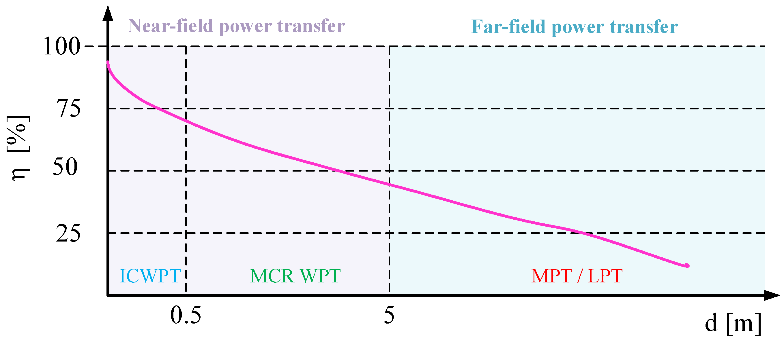
In turn, Figure 11 shows the dependence of the energy efficiency η on the distance d for the technologies discussed in Section 2 [16].
As was mentioned earlier and illustrated in Figure 11, the value of energy-transfer efficiency decreases with an increasing distance. It can be seen that in the range of short distances, this efficiency is the highest (between 68% and 95%), best obtained using the IWPT technology. Increasing the distance between the transmitter and the receiver requires a change in the technology of energy transfer and results in a reduction in energy efficiency to 45–65%. The lowest energy-transfer efficiency values are obtained using the far-field power transfer technology, where the efficiency value is significantly influenced by additional factors, e.g., weather conditions, the construction of the transmitter and the receiver, the type of metamaterials used to build components of the long-distance wireless energy-transfer system, etc.
As can be seen from the data summarized in Table 1, the highest value of the coupling coefficient occurs in the technology that uses the electric field to transmit electrical energy, but the distance in which it is possible to transmit this energy is the shortest. On the other hand, the technology that uses the resonance frequency to transfer power is characterized by the highest values of the operating frequency and no hysteresis losses, but unfortunately, it has a lower value of transmission efficiency than the IWPT. Additionally, with the MCR WPT technology, the factor that reduces the value of the considered efficiency is the significant losses incurred due to the eddy currents that arise. MCR WPT could operate at a lower signal frequency value, but as presented in the paper [57], that causes a decrease in the efficiency of the system and a decreased Q factor. The optimal value range for the frequency, at which a high efficiency can be obtained, is from 5 to 20 MHz.
On the other hand, it can be seen from the advantages and disadvantages of using various energy-transfer technologies, as summarized in Table 2, that the technology with the greatest potential is the IPT technology. Accordingly, that is the most frequently used electric energy-transfer technology due to the possibility of obtaining the highest transmission efficiency. Although IPT is characterized by the transfer of energy over short distances, its significant advantage is the possibility of transmitting energy of up to several kW. The second interesting technology that is still being developed is the CPT technology. However, it is currently characterized by a much lower efficiency of energy transfer than IPT and a shorter distance at which energy can be efficiently transmitted. Yet, this technology is still being developed, and in the literature, there are examples of CPT characterized by a high value of transmitted power. For example, the paper [58] presented a solution where using four instead of two plates of the capacitor and increasing their surface area obtained a power equal to 1.5 kW.
The other indicated technologies—belonging to the far-field power transfer group, such as MPT—are characterized by a very low efficiency of energy transfer. Additionally, the construction of the transmitter and the receiver is so expensive that they are currently not technologies with commercial potential.
4. Standards for Wireless Power Transfer
Even at the beginning of the 21st century, there was a lack of power standards for portable devices such as mobile phones. This resulted in different plugs for each phone model. To prevent such problems, attempts were made to introduce a single standard for wireless powering of electronic devices [59,60]. However, success in this area was achieved only partially, since, by 2015, three standards for wireless energy transfer had been developed:
- -
- QI standard [59];
- -
- PMA (Power Matters Alliance);
- -
- A4WP (Alliance for Wireless Power).
However, in 2015, PMA and A4WP then merged to form an organization, the AirFuel Alliance standard [61].
4.1. Qi Standard
The Qi standard (a Chinese name meaning the flow of life energy) was the first standard for wireless energy transfer, developed by the Wireless Power Consortium and introduced to the market in 2008 [60,62]. An improved version of this standard was then made available in 2010, and the manufacturer that promoted this standard was Nokia [58]. Later, other companies joined this standard, such as Toyota, LG, Samsung, Philips, Sony, Microsoft, Apple, Huawei, etc. [22,59].
This standard is the leading energy transfer standard and is dedicated to such transfer based on IPT technology [59,62,63]. This standard allows you to charge devices with a power from 5 to 15 W, for instance, smartphones. However, efforts are being made to increase the charging power from 30 to 60 W, which will allow for the wireless power supply of electronic devices requiring more power, e.g., laptops and tablets [54]. Yet, the limitations of this standard are heating, given the influence of temperature on the efficiency of energy transmission, the need to make adjustments (e.g., equalization of the transmitter and the receiver), and the possibility of charging only a single device.
The Qi standard distinguishes three types of transmitters that allow for obtaining the desired charging effect [59]: guided positioning, free positioning (moving the primary coil), and free positioning (the Qi coil matrix).
4.1.1. Guided Positioning
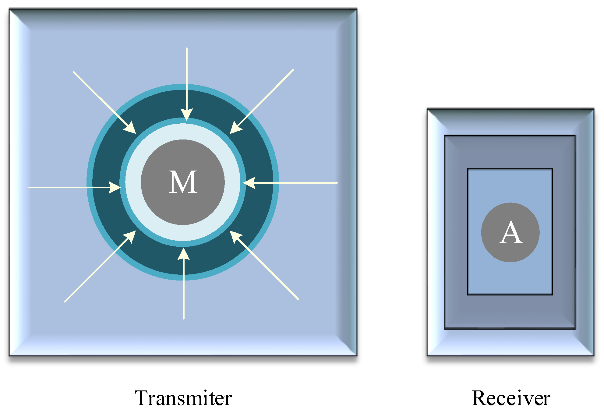
This is a standard that informs the user about the matching of the transmitter’s and the receiver’s positions. In the event of a mismatch, the user is informed how to move the receiver in relation to the transmitter to return them to their correct position for the most efficient charging [54]. Proper matching is possible thanks to the magnet inside the transmitter, which attracts the receiver containing the magnetic attractor. An example of this type of transmitter is shown in Figure 12.
This figure illustrates a typical configuration of the transmitter and the receiver for transmitting energy according to the Qi-guided positioning standard. As can be seen, in the central part of the transmitter, inside the coil, there is a magnet M, which is tasked with attracting the attractor contained in the receiver inside the coil. In this case, the aim is to place the attractor directly above the magnet, which will ensure a perfect match of both coils.
4.1.2. Free Positioning—Moving the Primary Coil
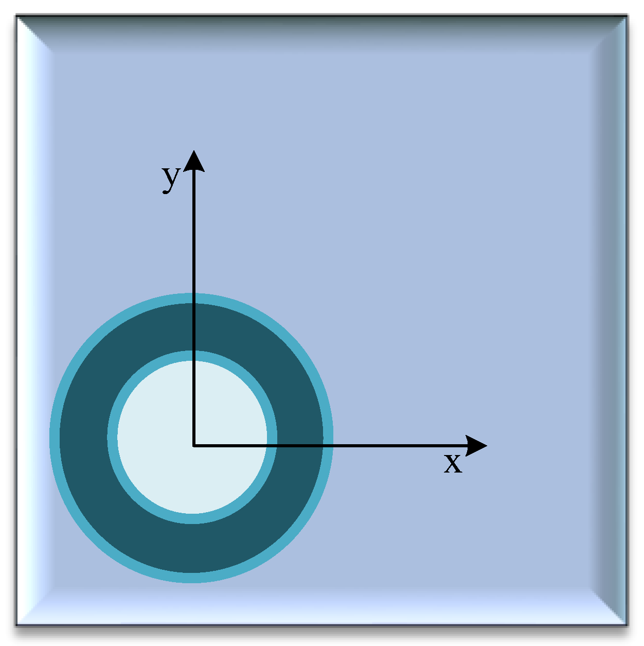
In this case, the positioning of the receiver in order to properly match the transmitter and the receiver is performed by changing the position of the primary coil to move it toward the receiver (Figure 13). To that end, the transmitter is equipped with a receiver detection and locating system. After detecting the receiver, the transmitter moves the coil on the side of the primary winding toward the receiver. The advantage of this solution, as in the case of guided positioning, is the use of only one coil in the transmitter. The accurate adjustment of the position between the coils requires the use of an appropriate mechanism that allows for changing the horizontal position of the coil in the transmitter [59].
As can be seen, the x- and y-axes indicate the possibility of moving the coil horizontally and vertically depending on the location of the receiver.
4.1.3. Free Positioning—Coil Matrix
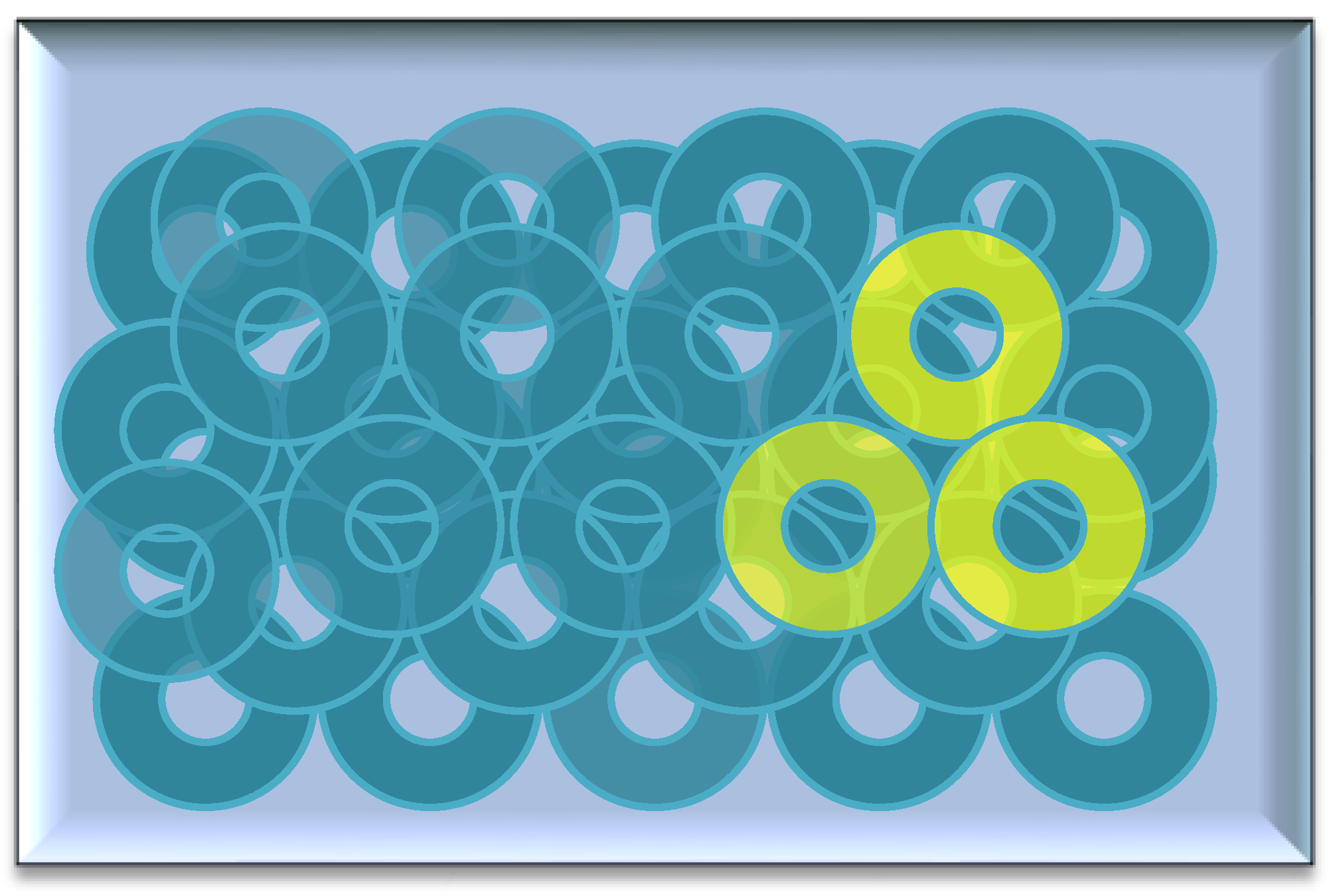
This type of transmitter includes an array of coils distributed over the entire surface of the transmitter. In this case, the arrangement of the transmitter and the receiver is more relaxed. To obtain a homogeneous distribution of the magnetic force, the coils are stacked in layers, generally forming three layers. The magnetic field generated by the sandwich coils is similar to the magnetic field generated by the previously described solutions. An advantage of this type of transmitter is that the positions of the transmitter and the receiver can be arbitrary, so long as they are within the magnetic force, meaning no precise alignment of the position between the transmitter and the receiver is required. However, a disadvantage of this solution is the challenge of implementing serial and layered positioning of the transmitter coils on the PCB, thereby keeping the quality at a satisfactory level [59]. An example of the implementation of a transmitter containing coils arranged in layers is shown in Figure 14.
This figure illustrates the transmitter consisting of a plurality of layered coils spread over the entire surface of its housing. These coils cannot move toward the receiver. On the other hand, when the receiver is within the range of the magnetic field generated by some of the transmitting coils (for example, marked in yellow), the transfer of electricity begins.
4.2. AirFuel Standard
The Power Matters Alliance Standard was introduced by the PMA, a non-profit organization that developed an energy transfer process using both IPT technologies [22]. Recently, as mentioned earlier, in a merger of the PMA organization with the A4WP, the AirFuel Alliance [61] standard was created. This standard has been adopted by such companies as Duracell, Starbucks, Flextronics, Samsung Electronics, Toshiba Corporation, etc. [61].
At present, the AirFuel Standard specializes mainly in AirFuel Resonant and RF energy resonance technologies. The advantage of the AirFuel Resonant standard is the fact that it is easy to install and scale and it costs less compared to an inductive power transfer solution. It was observed that AirFuel Resonant technology is implemented in public and private infrastructure in Asia [62]. This technology enables the transmission of energy over long distances (up to several meters) between the transmitter and the receiver at a frequency of 6.78 MHz [61].
5. Selected WPT Applications
As mentioned earlier, in recent years, there has been a significant increase in the interest in wireless charging. This technology is beginning to be widely used in various industries, such as automotive, electronic equipment (telephones, laptops), medicine, the military, and space. The type of energy transfer used is determined by a number of parameters that must be adapted to the device that requires a wireless power supply, e.g., size, the distance between the device containing the receiver and the transmitter, and the rated power [64]. From the point of view of power transfer over very long distances, it is additionally important to design an appropriate metamaterial that allows for increasing the efficiency of this transfer, characterized by the appropriate transmittance, permeability, and chirality [64]. In this subsection, as an example, the principle of wireless power transfer in the automotive industry is discussed.
Wireless Power Transfer in Electrical Vehicles
Currently, the dominant means of transport are vehicles with an internal combustion engine, which is the main cause of environmental pollution [65]. Taking into account the current problem with the availability of crude oil and gas, and striving to reduce the air pollution coefficient, electric cars (EVs) are becoming a good alternative. Electric cars are typically divided into two categories: hybrid electric vehicles (HEVs) and all-electric vehicles (AEVs). In the remainder of this section, we will focus only on all-electric cars. Typically, these cars use batteries, supercapacitors, and fuel cells as energy sources. Depending on the type of electric vehicle, it is possible to use one or more of the aforementioned sources. In turn, depending on the power source, they can be divided into battery-operated (BEV) vehicles requiring an external charging system, and fuel-cell-powered vehicles that do not require an external charging system.
In the literature, many papers are devoted to electric vehicles and their classification, configuration, standards for wired charging, etc. [65,66,67,68]. However, increasing attention is devoted to the wireless powering of electric vehicles [64]. This process most often uses the IPT method.
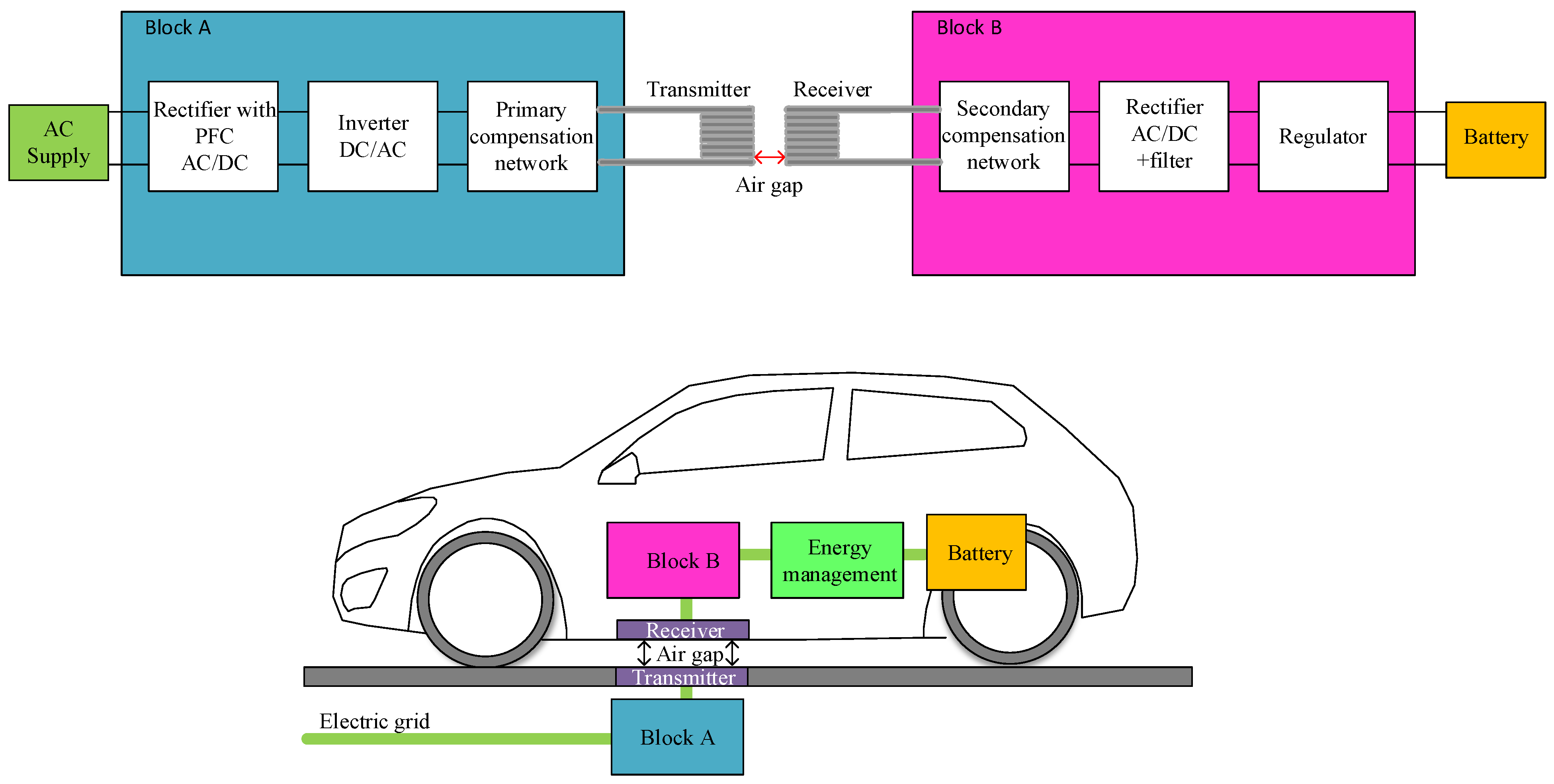
Figure 15 shows a typical wireless power supply topology dedicated to electric vehicles.
This system consists of the receiver located in the chassis of an electric car, while the transmitter is located under the road surface, parking lot, etc. The transmitter includes a low-frequency energy source, a converter with a power-factor correction system and a high-frequency inverter, a compensation coil, and a transmitting coil, also called the primary coil. In turn, the receiver circuit includes a resonant circuit that supplies power to the high-frequency rectifier, filter, and battery. The distance between the transmitter and the receiver depends on the type of vehicle, the thickness of the road surface, and the ground clearance, and usually does not exceed 0.4 m. The resonant frequency of the compensation system of the transmitting and receiving coils determines the required switching frequency of the inverters and usually ranges from 20 to 100 kHz [64]. In addition, as was described in the cited work, the efficiency of power transfer depends on the design of the coils (round, flat solenoid, bipolar, three-pole, zigzag) and the topology of the compensation system. This was widely described, inter alia, in [40,41,42]. In the paper [64], it was also pointed out that from an economic point of view, the most suitable topology of the compensation system for high-power systems is the topology of SS (series—series) and SP (series—parallel) [59]. An important block in the wireless power supply system for electric vehicles is also the block responsible for communication between the circuits to manage the demand for power [64].
The development of electric vehicles has created new opportunities in transport and electricity. However, for this new technology to work uniformly around the world, every aspect of it needs to be standardized. Standardization related to charging electric vehicles can be divided into three areas: standards for electric vehicle charging components, standards for integration with the EVGI (Electric Vehicle Grid Integration) network, and safety standards [64,65,69]. The main organization that standardizes all-electric vehicles is the International Organization for Standardization (ISO), while there are many other organizations that standardize the components of electric vehicle charging systems [65].
There are several standards available in the world for charging the infrastructure for electric vehicles. SAE and IEEE are used by US-based vehicle component manufacturers, while IEC is widely used in Europe [65]. In turn, Japan uses the standards CHAdeMO and China—Guobiao (GB/T). Detailed information on the aforementioned standardization is described, inter alia, in the papers [65,70,71].
The standards defined as IEC/ISO [65,72] apply to the most important standards for wireless power transfer in electric vehicles. These standards are summarized in Table 3.
As can be seen from the data presented in Table 3, there are eight standards for wireless power transfer in electric vehicles. The first standard is a general specification for the WPT and covers, inter alia, electromagnetic compatibility, the electromagnetic field, safety, tests, etc. The second standard is a document containing the recommendations for the design of power-transfer devices allowing for the maintenance of a high quality of power. The third standard is devoted to communication between the transmitter and the receiver and systematizes the types of messages that may be sent.
The fourth standard provides guidelines on how to limit the effects of electric and magnetic fields on human health. The fifth standard defines the procedure for workers with implanted pacemakers. This standard proposes different scenarios for carrying out a risk assessment. If an employee has other active implantable medical devices (AIMDs), these must be assessed separately. A specific approach involves the determination of the risk of exposure to electromagnetic fields for workers with implanted pacemakers.
The sixth standard specifies the requirements and the operation of the vehicle’s onboard equipment, which enables wireless power transfer in a magnetic field for charging electric vehicle traction batteries. It is intended for use in passenger cars and light commercial vehicles. This norm focuses, among others, on the transferred power, the distance between the transmitter and the receiver (clearance), the requirements for interoperability between differently classified EV (electric vehicle) devices and related systems outside vehicles, the performance requirements under different conditions, including these between different manufacturers and classifications, safety requirements, and test procedures.
The seventh standard regulates the method of information and energy exchange between electric cars, energy storage, and the operator’s electricity network. The eighth standard concerns a power supply device for charging electric vehicles using wireless methods with standardized rated voltages in accordance with the IEC 60038 of up to 1000 V AC and up to 1500 V DC. This standard specifies, inter alia, the characteristics and operating conditions of the power supply device, the specification of the required level of electrical safety for the power device, communication between the device and the vehicle to turn on and control the PTO (power take-off), the system performance, the mutual location and other conditions enabling wireless power transfer, and the specific electromagnetic compatibility (EMC) requirements for the supply device.
In the paper [15], it was pointed out that with an increase in the frequency of the WPT resonance system, the problem of big losses resulting from eddy currents may arise, which is the result of the magnetic flux penetrating the car chassis. The parameters of the coil may also change significantly. In such situations, it is worth using ferrite cores and an aluminum plate to shield the electromagnetic field.
In turn, the paper [73] discussed the use of passive and active shielding depending on the level of transferred power. It was shown that the use of passive shielding by a ferrite plate is a more effective method of shielding the electromagnetic field. The highest efficiency was demonstrated by materials with high relative permeability, which include, for example, ferrite material 3C95 offered by the Ferroxcube Company. As an added benefit, this material does not reduce the efficiency of the coils due to its high resistivity, which can minimize the losses due to eddy currents and losses in the core. If this procedure does not allow the magnetic flux density to be limited to a value below 27 µT, active shielding should be used through drift coils at the edges of the vehicle. However, this solution reduces the system’s performance.
On the other hand, the paper [74] presented a designed and implemented high-efficiency WPT system for charging small electric vehicles with a power of 500 W. As indicated, a very high efficiency of power transfer was obtained at a 15 cm air gap.
6. Final Remarks
WPT wireless power supply systems are a revolutionary technology for power transfer over various distances without the need to use the traditional connections: cables. Given the potential this holds, a breakthrough in the design of this type of system may occur in the near future, especially in the context of the components of the entire system. As the analysis we have presented here shows, the issues with these components are addressed increasingly in the literature, and WPT wireless power supply systems are coming to be used in various branches of the industry, ranging from small electronic devices used in medicine and implantology, through to portable devices for common uses, on to applications in the automotive, mining, and military industries.
At present, this technology has disadvantages, which we sought to point out, such as the dependence of the efficiency of electric energy transmission on the distance between the transmitter and the receiver. It was shown that an increase in the vertical distance between the transmitter and receiver results in an up to threefold reduction in the value of the coupling coefficient between the coils. Furthermore, a change in the horizontal position of the receiver in relation to the transmitter may result in a reduction in the value of the above-mentioned parameter by up to 50%.
We also noted how the shape of the coils has a significant influence on the properties of wireless electric-energy-transmission systems. The results of the analysis showed that the best properties, and most importantly of all, the highest value of power transfer efficiency, were obtained when both the transmitter and the receiver had a pentagonal shape. Additionally, it was noted that a high value of power transfer efficiency can be obtained by using ferromagnetic cores made of ferrite materials. The use of the aforementioned cores also allows for a reduction in losses related to the appearance of eddy currents or EMI disturbances. Yet, the potential efficiency still depends on the size of the transmitting and receiving coils, and in high-power systems, its value is significantly influenced by the parameters of the compensation system.
The literature also often refers to a factor limiting the properties of WPT as energy losses resulting from heating the components of this system, but not much work has yet been devoted to the issue. Overall, the issues related to wireless power transfer are topical and determining new areas of the research aimed at increasing the efficiency of power transfer in a safe, low-cost, and possibly less complicated manner.
Looking ahead, it is expected that WPT systems will continue to evolve and find wider applications. The efficiency of power transfer is also expected to increase in the years to come.
Author Contributions
Conceptualization, K.D. and K.G.; resources, K.D.; writing—original draft preparation, K.G. and K.D.; writing—review and editing, K.G. and K.D.; visualization, K.D.; supervision, K.G. All authors have read and agreed to the published version of the manuscript.
Funding
The project was financed under the framework of the program by the Ministry of Science and Higher Education called “Regionalna Inicjatywa Doskonałości” in the years 2019–2022, project number 006/RID/2018/19 (sum of financing: 11,870,000 PLN).
Data Availability Statement
Not applicable.
Conflicts of Interest
The authors declare no conflict of interest.
References
- Shan, D.; Wang, H.; Cao, K.; Zhang, J. Wireless power transfer system with enhanced efficiency by using frequency reconfigurable metamaterial. Sci. Rep. 2022, 12, 331. [Google Scholar] [CrossRef]
- Gore, V.B.; Gawali, D.H. Wireless power transfer technology for medical applications. In Proceedings of the Conference on Advances in Signal Processing (CASP), Pune, India, 9–11 June 2016; pp. 455–460. [Google Scholar] [CrossRef]
- Filipiak, M.; Głuchy, D. Analiza Wybranych Układów w Technice Bezprzewodowego Przesyłu Energii Elektrycznej. Pozn. Univ. Technol. Acad. J. 2013, 74, 227–235. [Google Scholar]
- Barsukov, Y.; Qian, J. Battery Power Management for Portable Devices, Artech House Power Engineering; Artech House: London, UK, 2013. [Google Scholar]
- Abdul-jabbar, T.A.; Obed, A.A.; Abid, A.J. Design of an Uninterrupted Power Supply with Li-Ion Battery Pack: A Proposal for a Cost-Efficient Design with High Protection Features. J. Technol. 2021, 3, 1–10. [Google Scholar] [CrossRef]
- Alam, B.; Islam, N.; Subhan ISarfraz, M. Analysis and Modelling of Basic Wireless Power Transfer Compensation Topology: A Review. In Intelligent Data Analytics for Power and Energy Systems; Lecture Notes in Electrical Engineering; Springer: Singapore, 2022; Volume 802. [Google Scholar] [CrossRef]
- Okoyeigbo, O.; Olajube, A.; Shobayo, O.; Aligbe, A.; Ibhaze, A.E. Wireless power transfer: A review. In IOP Conference Series: Earth and Environmental Science; IOP Publishing: Bristol, UK, 2021; Volume 012032, pp. 1–9. [Google Scholar] [CrossRef]
- Valone, T.F. Geoengineering Tesla’s Wireless Power Transmission, Extra Ordinary Science and Technology. 2017, pp. 31–42. Available online: https://www.researchgate.net/publication/320335847_Geoengineering_Tesla%27s_Wireless_Power_Transmission (accessed on 26 September 2022).
- Schuder, J.C.; Stephenson, H.E.; Townsend, J.F. High level electromagnetic energy transfer through a closed chestwall. IRE Int. Conv. Rec. 1961, 9, 119–126. [Google Scholar]
- Brown, W.C. The history of wireless power transmission. Solar Energy 1996, 56, 3–21. [Google Scholar] [CrossRef]
- Ongaro, F.; Summerer, L. Peter Glaser lecture: Space and a sustainable 21st century energy system. In Proceedings of the 57th International Astronautical Congress, Valencia, Spain, 3 October 2006. Paper IAC-06-C3.1.01. [Google Scholar]
- Kurs, A.; Karalis, A.; Moffatt, R.; Joannopoulos, J.D.; Fisher, P.; Soljacic, M. Wireless power transfer via strongly coupled magnetic resonances. Science 2007, 6, 86. [Google Scholar] [CrossRef] [Green Version]
- Rim, C.T.; Mi, C. Wireless Power Transfer for Electric Vehicles and Mobile Devices; John Wiley and Sons: West Sussex, UK, 2017. [Google Scholar]
- Qiu, C.; Chau, K.T.; Liu, C.; Chan, C.C. Overview of wireless power transfer for electric vehicle charging. In Proceedings of the 2013 World Electric Vehicle Symposium and Exhibition (EVS27), Barcelona, Spain, 17–20 November 2013; pp. 1–9. [Google Scholar] [CrossRef]
- Li, S.; Mi, C.C. Wireless Power Transfer for Electric Vehicle Applications. IEEE J. Emerg. Sel. Top. Power Electron. 2015, 3, 4–17. [Google Scholar] [CrossRef]
- Mohsan, S.A.H.; Khan, M.A.; Rokia LS, R.; Islam, A.; Mahmood, A.; Mazinani, A.; Amjad, H. A review on Research Challenges, Limitation and Practical Solution for Underwater Wireless Power Transfer. Int. J. Adv. Comput. Sci. Appl. 2020, 11, 554–562. [Google Scholar] [CrossRef]
- Coca, E. Wireless Power Transfer Fundamentals and Technologies; InTechOpen: London, UK, 2016. [Google Scholar]
- Moore, J.; Castellanos, S.; Xu, S.; Wood, B.; Ren, H.; Tse, Z.T.H. Applications of Wireless Power Transfer in Medicine: State-of-the-Art Reviews. Ann. Biomed. Eng. 2018, 47, 22–38. [Google Scholar] [CrossRef] [PubMed] [Green Version]
- Barbruni, G.L.; Ros, P.M.; Demarchi, D.; Carrara, S.; Ghezzi, D. Miniaturised Wireless Power Transfer Systems for Neurostimulation: A Review. IEEE Trans. Biomed. Circuits Syst. 2020, 14, 1160–1178. [Google Scholar] [CrossRef]
- Kim, J.D.; Sun, C.; Suh, I.S. A proposal on wireless power transfer for medical implantable applications based on reviews. In Proceedings of the 2014 IEEE Wireless Power Transfer Conference, Jeju, Korea, 19 June 2014; pp. 166–169. [Google Scholar] [CrossRef]
- Kuka, S.; Ni, K.; Alkahtani, M. A review of method and challenges for Improvement in Efficiency and Distance for Wireless Power Transfer. Power Electron. Driv. 2020, 5, 1–25. [Google Scholar] [CrossRef]
- Sidiku, M.B.; Eronu, E.M.; Ashigwuike, E.C. Review On Wireless Power Transfer: Concepts, Implementations, Challenges, and Mitigation. Niger. J. Technol. 2020, 39, 1206–1215. [Google Scholar] [CrossRef]
- Zhang, Z.; Pang, H.; Georgiadis, A.; Cecati, C. Wireless Power Transfer—An Overview. IEEE Trans. Ind. Electron. 2019, 66, 1044–1058. [Google Scholar] [CrossRef]
- Foote, A.; Onar, O.C. A review of high-power wireless power transfer. In Proceedings of the 2017 IEEE Transportation Electrification Conference and Expo (ITEC), Chicago, IL, USA, 22 June 2017; pp. 234–240. [Google Scholar] [CrossRef]
- Popovic, Z. Near- and Far-Field Wireless Power Transfer. In Proceedings of the 2017 13th International Conference on Advanced Technologies, Systems and Services in Telecommunications (TELSIKS), Nis, Serbia, 18–20 October 2017. [Google Scholar]
- Lin, W.; Ziolkowski, R.W. Far field wireless power transfer for IoT applications enabled by an ultra-compact and highly-efficient Huygens rectenna. In Proceedings of the 2020 IEEE Wireless Power Transfer Conference (WPTC), Seoul, Korea, 24 December 2020; pp. 69–71. [Google Scholar] [CrossRef]
- Zhang, H.; Shlezinger, N.; Guidi, F.; Dardari, D.; Imani, M.F.; Eldar, Y.C. Near-Field Wireless Power Transfer for 6G Internet of Everything Mobile Networks: Opportunities and Challenges. IEEE Commun. Mag. 2022, 60, 12–18. [Google Scholar] [CrossRef]
- Wang, C.; Xu, W.; Zhang, C.; Wang, M.; Wang, X. Microwave wireless power transmission technology index system and test evaluation methods. EURASIP J. Adv. Signal Process. 2022, 16, 2478. [Google Scholar] [CrossRef]
- Jin, K.; Zhou, W. Wireless Laser Power Transmission: A Review of Recent Progress. IEEE Trans. Power Electron. 2018, 34, 3842–3859. [Google Scholar] [CrossRef]
- Zhang, Q.; Fang, W.; Liu, Q.; Wu, J.; Xia, P.; Yang, L. Distributed Laser Charging: A Wireless Power Transfer Approach. IEEE Internet Things J. 2018, 5, 3853–3864. [Google Scholar] [CrossRef] [Green Version]
- Wang, X.; Lu, C.; Wang, C.; Liu, P.; Xu, W.; Zhou, Y.; Wang, F. Methods for testing the performance of long-distance wireless power transmission systems. EURASIP J. Wirel. Commun. Netw. 2020, 2020, 2536. [Google Scholar] [CrossRef]
- Dang, K.; Zhang, J.; Zhou, H.; Huang, S.; Zhang, T.; Bian, Z.; Zhang, Y.; Wang, X.; Zhao, S.; Wei, K.; et al. A 5.8-GHz High-Power and High-Efficiency Rectifier Circuit with Lateral GaN Schottky Diode for Wireless Power Transfer. IEEE Trans. Power Electron. 2020, 35, 2247–2252. [Google Scholar] [CrossRef]
- Zheng, S.; Liu, W.; Pan, Y. Design of an Ultra-Wideband High-Efficiency Rectifier for Wireless Power Transmission and Harvesting Applications. IEEE Trans. Ind. Inform. 2019, 15, 3334–3342. [Google Scholar] [CrossRef]
- Liu, H.; Zhang, Y.; Hu, Y.; Tse, Z.; Wu, J. Laser Power Transmission and Its Application in Laser-Powered Electrical Motor Drive: A Review. Power Electron. Drives 2021, 6, 167–184. [Google Scholar] [CrossRef]
- Kim, D.; Abu-Siada, A.; Sutinjo, A. State of the art literature review of WPT: Current limitations and solutions on ITP. Electr. Power Syst. Res. 2018, 154, 493–502. [Google Scholar] [CrossRef]
- Mohammed, S.S.; Ramasamy, K.; Shanmuganantham, T. Wireless Power Transmision—A next generation power transmission system. Int. J. Comput. Appl. 2010, 1, 102–105. [Google Scholar] [CrossRef]
- Theodoridis, M. Effective Capacitive Power Transfer. IEEE Trans. Power Electron. 2012, 27, 4906–4913. [Google Scholar] [CrossRef]
- Covic, G.A.; Boys, J.T. Inductive Power Transfer. Proc. IEEE 2013, 101, 1276–1289. [Google Scholar] [CrossRef]
- Van den Bossche, A.; Valchev, V. Inductor and Transformers for Power Electronic; CRC Press: Boca Raton, FL, USA, 2005. [Google Scholar]
- Wen, F.; Chu, X.; Li, Q.; Gu, W. Compensation Parameters Optimization of Wireless Power Transfer for Electric Vehicles. Electronics 2020, 9, 789. [Google Scholar] [CrossRef]
- Badwey, M.A.; Abbasy, N.H.; Eldallal, G.M. An efficient design of LC-compensated hybrid wireless power transfer system for electric vehicle charging applications. Alex. Eng. J. 2022, 61, 6565–6580. [Google Scholar] [CrossRef]
- Song, S.; Zhang, W.; Jin, Z.; Geng, Q. Analysis of S-S Resonance Compensation Circuit of Electric Vehicle Wireless Power Transfer System. In Proceedings of the IEEE 4th Conference on Energy Internet and Energy System Integration (EI2), Wuhan, China, 15 February 2020; pp. 619–622. [Google Scholar] [CrossRef]
- Rakhymbay, A.; Bagheri, M.; Lu, M. A simulation study on four different compensation topologies in EV wireless charging. In Proceedings of the International Conference on Sustainable Energy Engineering and Application (ICSEEA), Jakarata, Indonesia, 23–24 October 2017; pp. 66–73. [Google Scholar] [CrossRef]
- Wang, H.S.; Cheng, K.W.E.; Hu, J.F. An Investigation of Compensation Networks for Three-coil Wireless Power Transfer. In Proceedings of the 8th International Conference on Power Electronics Systems and Applications (PESA), Hong Kong, China, 7–10 December 2020; pp. 1–6. [Google Scholar]
- Geng, Y.; Sun, H.; Yang, Z.; Li, B.; Lin, F. A High Efficiency Charging Strategy for a Supercapacitor Using a Wireless Power Transfer System Based on Inductor/Capacitor/Capacitor (LCC) Compensation Topology. Energies 2017, 10, 135. [Google Scholar] [CrossRef]
- Moradewicz, A.; Miśkiewicz, R. Systemy bezstykowanego zasilania komputerów przenośnych. Pr. Inst. Elektrotechniki 2008, 236, 47–62. [Google Scholar]
- Marcinek, M. Rezonansowy układ przekształtnikowy z aktywną stabilizacją punktu pracy w systemach bezstykowego przekazywania energii. Ph.D. Thesis, Zachodniopomorski Uniwersytet Technologiczny w Szczecinie, Szczecin, Poland, 2015. [Google Scholar]
- Kevin, L. Comparative Study of Different Coil Geometries for Wireless Power Transfer. 2016. Available online: https://www.google.com/url?sa=t&rct=j&q=&esrc=s&source=web&cd=&ved=2ahUKEwiXof739aX6AhUBtYsKHbwWDMYQFnoECAgQAQ&url=http%3A%2F%2Futpedia.utp.edu.my%2F17133%2F1%2FFinal%2520Dissertation%2520%2528Final%2529%2520-%2520Lau%2520Kevin%252016392.pdf&usg=AOvVaw3IoxNm3qaKiYuzHRc362S9 (accessed on 26 September 2022).
- Filipiak, M.; Głuchy, D.; Godek, M. Wpływ technologii stosowanych w ładowarkach bezprzewodowych na proces ładowania urządzeń mobilnych. Pozn. Univ. Technol. Acad. J. Electr. Eng. 2019, 41–51. [Google Scholar] [CrossRef]
- Murakami, R.; Inamori, M.; Morimoto, M. Effects of Q factor on wireless power transmission by magnetic resonant coupling. In Proceedings of the IEEE International Conference on Power and Renewable Energy (ICPRE), Shanghai, China, 21–23 October 2016; pp. 139–143. [Google Scholar] [CrossRef]
- Wen, H.; Zhang, C. Investigation on transmission efficiency for magnetic materials in a wireless power transfer system. In Proceedings of the IEEE 11th International Conference on Power Electronics and Drive Systems, Sydney, Australia, 9–12 June 2015; pp. 249–253. [Google Scholar] [CrossRef]
- Lu, F.; Zhang, H.; Mi, C. A Review on the Recent Development of Capacitive Wireless Power Transfer Technology. Energies 2017, 10, 1752. [Google Scholar] [CrossRef] [Green Version]
- Panchal, C.; Stegen, S.; Lu, J.-W. Review of static and dynamic wireless electric vehicle charging system. Eng. Sci. Technol. Int. J. 2018, 21, 922–937. [Google Scholar] [CrossRef]
- Lecluyse, C.; Minnaert, B.; Kleemann, M. A Review of the Current State of Technology of Capacitive Wireless Power Transfer. Energies 2021, 14, 5862. [Google Scholar] [CrossRef]
- Al-Saadi, M.; Al-Bahrani, L.; Al-Qaisi, M.; Al-Chlaihawi, S.; Crăciunescu, A. Capacitive Power Transfer for Wireless Batteries Charging. Electroteh. Electron. Autom. 2018, 66, 40–51. [Google Scholar]
- Mou, X.; Sun, H. Wireless Power Transfer: Survey and Roadmap. In Proceedings of the IEEE 81st Vehicular Technology Conference (VTC Spring), Glasgow, UK, 11–14 May 2015; pp. 1–5. [Google Scholar] [CrossRef]
- Pham, T.S.; Nguyen, T.D.; Tung, B.S.; Khuyen, B.X.; Hoang, T.T.; Ngo, Q.M.; Hiep, L.T.H.; Lam, V.D. Optimal frequency for magnetic resonant wireless power transfer in conducting medium. Sci. Rep. 2021, 11, 18690. [Google Scholar] [CrossRef] [PubMed]
- Olszyna, J.; Winiecki, W. Metody pozyskiwania energii dla autonomicznych bezprzewodowych sieci czujników. Pomiary Autom. Kontrola 2012, 58, 837–839. [Google Scholar]
- Van Wageningen, D.; Staring, T. The Qi Wireless Power Standard. In Proceedings of the 14th International Power Electronics and Motion Control Conference (EPE-PEMC 2010), Ohrid, Macedonia, 6–8 September 2010; pp. 15–25. [Google Scholar]
- El Rayes, M.M.; Nagib, G.; Ali Abdelaal, W.G. A Review on Wireless Power Transfer. Int. J. Eng. Trends Technol. 2016, 40, 272–280. [Google Scholar] [CrossRef]
- Airfuel Standard Consorcium Website. Available online: https://airfuel.org/ (accessed on 26 September 2022).
- Houran, M.A.; Yang, X.; Chen, W.; Samizadeh, M. Wireless Power Transfer: Critical Review of Related Standards. In Proceedings of the 2018 International Power Electronics Conference (IPEC-Niigata 2018-ECCE Asia), Nagatiia, Japan, 20–24 November 2018; pp. 1062–1066. [Google Scholar] [CrossRef]
- Article available online: Wired, Qi Wireless Charging: What Is It And How Does It Work In Nokia’s Lumia 920? Available online: https://www.wired.co.uk/article/what-is-qi-wireless-charging (accessed on 5 September 2012).
- Iqteit, N.; Yahya, K.; Khan, S.A. Wireless Power Charging in Electrical Vehicles; Intechopen: London, UK, 2021. [Google Scholar] [CrossRef]
- Das, H.S.; Rahman, M.M.; Li, S.; Tan, C.W. Electric vehicles standards, charging infrastructure, and impact on grid integration: A technological review. Renew. Sustain. Energy Rev. 2020, 120, 109618. [Google Scholar] [CrossRef]
- Tie, S.F.; Tan, C.W. A review of energy sources and energy management system in electric vehicles. Renew Sustain. Energy Rev. 2013, 20, 82–102. [Google Scholar] [CrossRef]
- Hannan, M.; Azidin, F.; Mohamed, A. Hybrid electric vehicles and their challenges: A review. Renew Sustain. Energy Rev. 2014, 29, 135–150. [Google Scholar] [CrossRef]
- Hannan, M.; Hoquebc, M.M.; Mohamedb, A.; Ayobb, A. Review of energy storage systems for electric vehicle applications: Issues and challenges. Renew Sustain. Energy Rev. 2017, 69, 771–789. [Google Scholar] [CrossRef]
- Morrissey, P.; Weldon, P.; O’Mahony, M. Future standard and fast charging infrastructure planning: An analysis of electric vehicle charging behaviour. Energy Policy 2016, 89, 257–270. [Google Scholar] [CrossRef]
- Electric Vehicle Standards Website. Available online: https://0-standards-ieee-org.brum.beds.ac.uk/products-programs/icap/programs/ev/ (accessed on 26 September 2022).
- Arif, S.; Lie, T.; Seet, B.; Ayyadi, S.; Jensen, K. Review of Electric Vehicle Technologies, Charging Methods, Standards and Optimization Techniques. Electronics 2021, 10, 1910. [Google Scholar] [CrossRef]
- Ahmad, A.; Alam, M.S.; Chabaan, R. A Comprehensive Review of Wireless Charging Technologies for Electric Vehicles. IEEE Trans. Transp. Electr. 2017, 4, 38–63. [Google Scholar] [CrossRef]
- Zhang, B.; Carlson, R.B.; Smart, J.G.; Dufek, E.J.; Liaw, B. Challenges of future high power wireless power transfer for light-duty electric vehicles—Technology and risk management. eTransportation 2019, 2, 100012. [Google Scholar] [CrossRef]
- Hsieh, Y.C.; Lin, Z.R.; Chen, M.C.; Hsieh, H.C.; Liu, Y.C.; Chiu, H.J. High-Efficiency Wireless Power Transfer System for Electric Vehicle Applications. IEEE Trans. Circuits Syst. II Express Briefs 2017, 64, 942–946. [Google Scholar] [CrossRef]
Figure 1.
Classification of wireless power transfer.

Figure 2.
Wireless power transfer using inductive technology.

Figure 3.
Wireless power transfer system—IPT.

Figure 4.
Changing the position: horizontally (a), vertically (b), and at the angle (c) of the transmitting and receiving coils with a rectangular cross-section.
Figure 4.
Changing the position: horizontally (a), vertically (b), and at the angle (c) of the transmitting and receiving coils with a rectangular cross-section.

Figure 5.
Influence of changing the horizontal position (a), vertical position (b), and the angle (c) of the transmitting and receiving coils with a rectangular cross-section on the coupling factor.
Figure 5.
Influence of changing the horizontal position (a), vertical position (b), and the angle (c) of the transmitting and receiving coils with a rectangular cross-section on the coupling factor.

Figure 6.
Circuits for wireless power transmission containing the transmitting and receiving coils in (a) square, (b) oval, and (c) pentagonal shapes.
Figure 6.
Circuits for wireless power transmission containing the transmitting and receiving coils in (a) square, (b) oval, and (c) pentagonal shapes.

Figure 7.
Dependence of the output power (a), energy transmission efficiency (b), and coupling coefficient (c) on the distances between the coils of different shapes.
Figure 7.
Dependence of the output power (a), energy transmission efficiency (b), and coupling coefficient (c) on the distances between the coils of different shapes.

Figure 8.
Dependence of the transmitted power between the transmitting and receiving coils (a) and the efficiency of energy transmission (b) on the quality factor of the coils.
Figure 8.
Dependence of the transmitted power between the transmitting and receiving coils (a) and the efficiency of energy transmission (b) on the quality factor of the coils.

Figure 9.
Dependence of the efficiency of energy transmission on the frequencies of various ferromagnetic materials.
Figure 9.
Dependence of the efficiency of energy transmission on the frequencies of various ferromagnetic materials.

Figure 10.
Wireless power transfer—CPT.

Figure 11.
Efficiency of wireless energy-transfer systems depending on the distance between the transmitter and the receiver.
Figure 11.
Efficiency of wireless energy-transfer systems depending on the distance between the transmitter and the receiver.

Figure 12.
Transmitter with guided positioning.

Figure 13.
Transmitter with free positioning—moving the coil.

Figure 14.
Transmitter with free positioning—matrix coil.

Figure 15.
Wireless charging system designed for electric vehicles.


Table 1.
Comparison of parameters of various IPT technologies [56].
Table 1.
Comparison of parameters of various IPT technologies [56].
| Parameter | MCR WTP | IWPT | CTP |
|---|---|---|---|
| Operating frequency | Very high | High | Medium |
| Hysteresis losses | None | Appear | Appear |
| Eddy current losses | High | Medium | Low |
| Coupling coefficient | <0.25 | >0.5 | ~1 |
| Efficiency | Medium | High | Medium |
| Distance | Medium | Medium | Low |
Table 2.
Advantages and disadvantages of the WPT technology [29].
Table 2.
Advantages and disadvantages of the WPT technology [29].
| CTP | ITP | MPT | LPT | |
|---|---|---|---|---|
| Advantages | High power transfer (up to several kW) | Possible to obtain a higher efficiency (90%) | Long effective transmission distance of up to several km | Long effective transmission distance of up to several km |
| Transfers power without generating an eddy current | High power transfer (for several kW) | Suitable for mobile phones | Suitable for mobile phones | |
| Reduces costs by using metal plates as the transmitter and receiver | Good galvanic isolation | Has the potential to transfer several kW | Has the potential to transfer several kW | |
| Very good for small applications but can also be used in large applications such as electric vehicles | Can be applied from small (phone) to large devices (electric vehicles) | |||
| Disadvantages | Limited efficiency in the range of 70–80% | Limited transmission distance from cm to m | Low efficiency, less than 10% | Low efficiency, less than 20% |
| Short transmission distance (max. 100 mm) | The significant eddy current losses limit the application area | Complex implementation | The line of sight to the receiver | |
| Some challenges as a result of conflict between the transfer distance, power, and capacitance value |
| No. | Standard | Description |
|---|---|---|
| 1. | SAE J2954 | Wireless power transfer for light-duty plug-in/electric vehicles and alignment methodology |
| 2. | SAE J2894/1 | Power quality requirements for plug-in electric vehicle chargers |
| 3. | SAE J2847/6 | Communication between wireless charged vehicles and wireless EV chargers |
| 4. | SAE J2931/6: ICNIRP 2010 | ICNIRP guidelines for limiting exposure to time-varying electric and magnetic fields (1–100 kHz) |
| 5. | ISO 14117:2012 | Active implantable medical devices—Electromagnetic compatibility—EMC test protocols for implantable cardiac pacemakers, implantable cardioverter defibrillators, and cardiac resynchronization devices |
| 6. | ISO/PAS 19363:2017 | Electrically propelled road vehicles—Magnetic field wireless power transfer—Safety and interoperability requirements |
| 7. | ISO 15118 | Road vehicles—Vehicle-to-grid communication interface |
| 8. | IEC61980–1 | Electric vehicle wireless power transfer (WPT) systems—Part 1: General requirements |
Publisher’s Note: MDPI stays neutral with regard to jurisdictional claims in published maps and institutional affiliations. |
© 2022 by the authors. Licensee MDPI, Basel, Switzerland. This article is an open access article distributed under the terms and conditions of the Creative Commons Attribution (CC BY) license (https://creativecommons.org/licenses/by/4.0/).
Share and Cite
MDPI and ACS Style
Detka, K.; Górecki, K. Wireless Power Transfer—A Review. Energies 2022, 15, 7236. https://0-doi-org.brum.beds.ac.uk/10.3390/en15197236
AMA Style
Detka K, Górecki K. Wireless Power Transfer—A Review. Energies. 2022; 15(19):7236. https://0-doi-org.brum.beds.ac.uk/10.3390/en15197236
Chicago/Turabian StyleDetka, Kalina, and Krzysztof Górecki. 2022. "Wireless Power Transfer—A Review" Energies 15, no. 19: 7236. https://0-doi-org.brum.beds.ac.uk/10.3390/en15197236
Note that from the first issue of 2016, this journal uses article numbers instead of page numbers. See further details here.