
Frequency Fluctuation Mitigation in a Single-Area Power System Using LQR-Based Proportional Damping Compensator


1
Department of Electronics & Telecommunication Engineering, Rajshahi University of Engineering & Technology, Rajshahi 6204, Bangladesh
2
School of Electrical, Computer and Telecommunication Engineering, University of Wollongong, Wollongong, NSW 2522, Australia
*
Author to whom correspondence should be addressed.
Energies 2023, 16(12), 4804; https://0-doi-org.brum.beds.ac.uk/10.3390/en16124804
Submission received: 31 May 2023
/
Revised: 15 June 2023
/
Accepted: 18 June 2023
/
Published: 19 June 2023
(This article belongs to the Special Issue Planning, Operation and Control of Renewable Energy Sources and Energy Storage Devices Assisted Hybrid Power System)
Abstract
:To maintain the stability of the power system, frequency fluctuations must be reduced in the shortest possible timeframe. Load frequency control (LFC) plays a critical role in achieving this objective by regulating the system frequency and the desired demand or output power in an interconnected network, thereby enabling the system to adapt the load disturbances. In order to effectively mitigate the frequency fluctuation caused by load variation in a single-area power system, a new control strategy integrating a linear quadratic regulator (LQR), a proportional controller, and a damping compensator is proposed in this paper. The proposed controller is named as the LQR-based proportional damping compensator which mitigates the frequency fluctuation of a single-area power system. MATLAB/Simulink simulation is conducted on a single-area power system to demonstrate the efficacy of the proposed control technique. The simulation results demonstrate that the proposed method successfully reduces frequency variations, maintains system frequency within reasonable limits, and substantially reduces the settling time as compared to other existing control techniques. Apart from the simulation analysis, to experimentally validate the performance of the proposed controller, a hybrid multiprocessor-based processor-in-loop (PIL) technique is also introduced in the paper. Both the simulation and experimental results prove the promising performance of the proposed controller for mitigating the frequency fluctuation of a single-area power system.
1. Introduction
Maintaining the frequency of a power system within acceptable limits is essential for a power system to be stable and to operate with reliability. Due to the fluctuation in consumer demand, the power varies and any change in real power mostly influences the system frequency. A synchronous generator (SG) is used in conventional power generating stations, particularly in steam, hydro, gas, or combined-cycle power plants, to produce electricity with the aid of a turbine and speed governor [1]. Under both static and dynamic conditions, the generators in the control zone periodically change their combined speeds (acceleration or deceleration) to maintain the frequency and the corresponding power angle at predetermined levels [2,3]. Load frequency control (LFC) refers to the issue of regulating the actual electrical output of producing units in response to alterations in system frequency and the exchange of patch line power within predetermined constraints. The LFC stabilizes the frequency and power profile of the connection line after controlling power generation in the demand-load line to reduce the temporal average of the zone control error [4,5].
Automatic generation control (AGC), pole placement design, and optimal control design are currently the most advanced techniques for preserving the power system’s frequency against variations in active power load. In optimal control design, the control system employs the state-variable feedback technique, which is implemented by diminishing the system variables’ performance indices [6]. Proportional–integral–derivative (PID) controller, linear quadratic regulator (LQR), model predictive control (MPC), and sliding mode control (SMC) are some optimal controllers which can be used for load frequency control [7,8,9,10]. Additionally, a variety of artificial intelligence methods have been developed for implementation in LFC, with fuzzy logic and artificial neural networks (ANN) being the most frequently used.
To enhance the overall system dynamics, a PID controller was suggested in [11]. The suggested controller had a negligible overshoot but the settling time required was approximately 6 s. However, there is a zero steady-state error in a PID-controlled system. It was shown that the frequency response would stabilize significantly more quickly than a PID-controlled system by using an advanced optimization technique. In [12], a novel stability criterion was developed with a proportional–integral (PI)-based LFC to assess the influence of the time-varying delay on the stability of power systems. Active disturbance rejection control (ADRC) for a wind-integrated power system LFC was presented in paper [13] considering delays in communication. In order to enhance the stability of frequency control, equivalent input disturbance (EID) compensation is utilized to eliminate the impact of load variation. Based on a frequency-domain approach, paper [14] presented a fractional-order PID controller cascaded with a first-order filter for the delayed LFC system. In order to stabilize the system, a PID-based secondary controller was suggested using a modified variant of particle swarm optimization in [15]. In [16], authors analyzed the methods for dealing with the uncertainty of renewable energy and controller for a multi-area power system. In [17], a tuning-free PID control method was presented for a second-order plus time delay (SOPTD) system. In paper [18,19,20], an LFC power system was implemented with a PI-type SMC. Because of the use of PI, the required settling time is comparatively high.
Thus, by replacing PID controllers with optimal control techniques, the system response could be improved more in terms of robustness. To avoid the issues faced by a classical I or PI or PID controller, an optimal control may be used to control the system. In [10], an optimal control method called a linear quadratic regulator (LQR) was suggested where the transient responses of the control system were significant as the required settling time was approximately 0.7 s. Despite offering better settling time performance, the LQR controller has a notable steady-state error.
Furthermore, the application of the aforementioned controllers is not limited to the LFC of conventional power systems. A new optimization technique named the African Vulture Optimization Algorithm was presented to ensure the performance of a cascaded controller in [21]. To mitigate the problem of the renewable energy source (RES) for a two-area interconnected network, this controller was introduced. Including battery and pump hydro as new applications, ref. [22] described the frequency and power control of a microgrid power system. For the control technique, the optimal tuning of the PI controller using the quasi-Newton method was considered. In [23], the quasi-Newton algorithm for hybrid power plant operation was presented and contrasted to a standard PID controller. In [24], the fractional-order proportional–integral–derivative (FOPID) controllers were proposed in relation to regulating the temperature in ambulances, regulating bioreactors, induction heating systems, and the advancement of temperature control systems. This optimal PID performs better than traditional PID in terms of responses according to the timing information. The LQR controller has additional applications beyond LFC. In [25], an energy management system for battery supercapacitor hybrid systems containing a battery (lithium-ion) and a supercapacitor along with a bidirectional DC-DC converter was presented. For three-area power systems, ref. [26] analyzed the performance of model-based LQR and data-driven fuzzy controllers. Based on the comparison, it can be seen that the LQR strategy outperforms the fuzzy control strategy.
For the effective control of system frequency with respect to frequency deviation, steady-state error, and settling time, a new optimal control technique is proposed in this paper for the mitigation of frequency fluctuations in a single-area power system implementing an LQR-based proportional damping compensator.
The proposed control technique comprises a proportional controller, a damping compensator, and an LQR. To enhance the system’s tracking performance, an optimal state feedback controller is designed using the LQR, and damping compensator, and it is then paired with a proportional controller. The damping compensator’s purpose is to minimize low-frequency oscillations that occur due to load variations. Based on the relevant literature survey and the proposition of the paper, it is evident that this article brings a new look to the existing literature in the following areas: (I) introduction of robust hybrid control technique (II) experimental analysis of complicated power system model, and (III) wide range of responses of a power system model. The key contributions of the paper are summarized as follows:
- A new LQR-based proportional damping compensator is proposed to mitigate the frequency fluctuation of a single-area power system;
- A hybrid multiprocessor-based processor-in-loop (PIL) technique is introduced in the paper to validate the performance of the proposed control strategy; and
- The performance of the proposed controller is evaluated both in simulation and experimental environments in terms of frequency deviation, settling time, and steady-state error for various load conditions.
The rest of the paper is organized as follows: the modeling of the single-area power system is presented in Section 2, while Section 3 describes the design of the proposed controller; simulation result analysis is presented in Section 4 and experimental analysis is included in Section 5; finally, Section 6 concludes the paper.
2. Modeling of the Single-Area Power System
LFC is a crucial control problem because it controls the system frequency and inter-area tie-line power to determine the quality of power generation [27]. The single-area power system stands for a power system network consisting of a governor, turbine, and rotating mass with load. This is the basic unit of a power system network. If more than one single-area network is connected in a cascaded manner, the resulting power system network is said to be a multi-area power system. In this work, the mitigation of frequency fluctuation is targeted on a single area network using an LQR-based proportional damping compensator-based control technique.
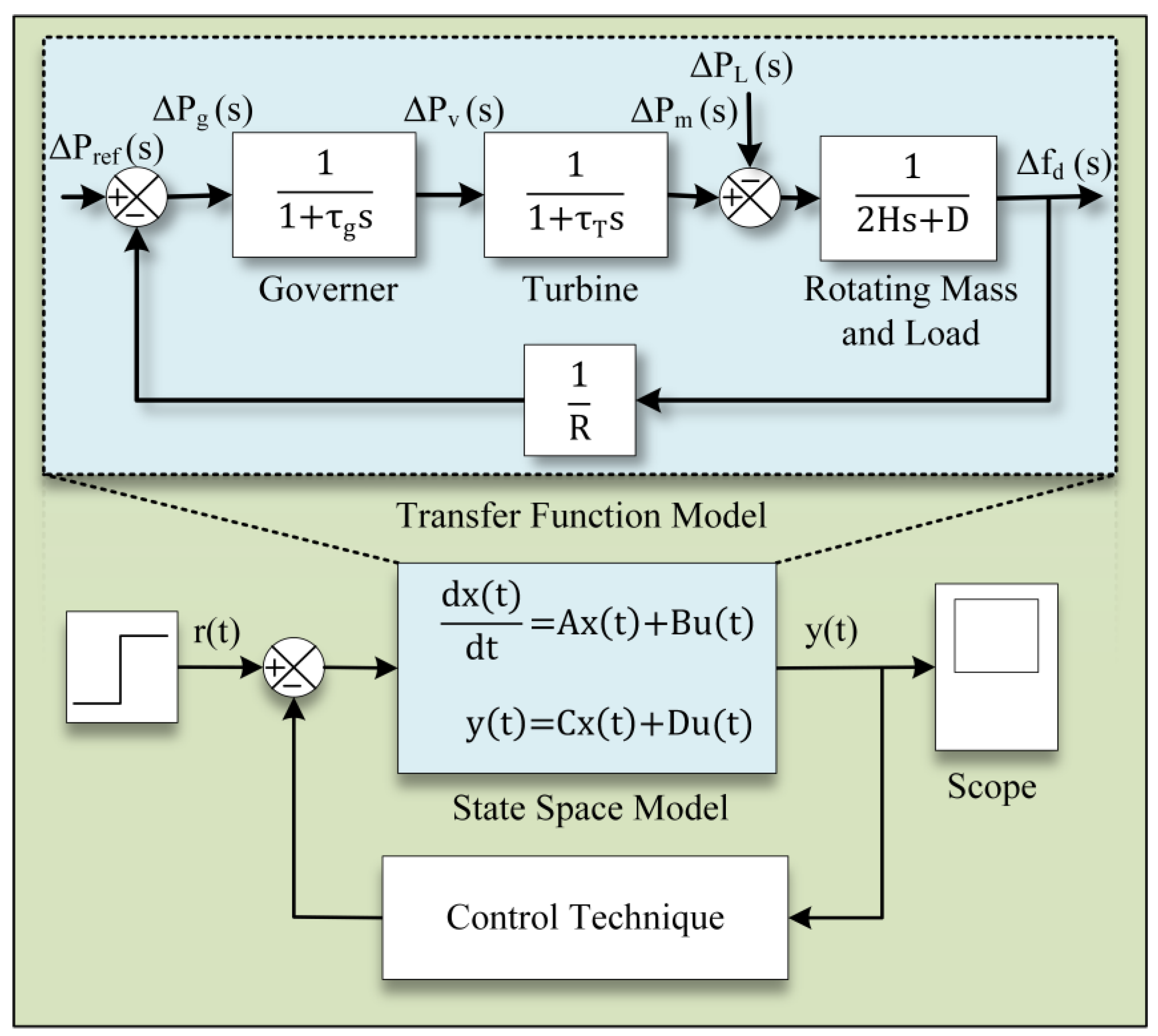
The key characteristic of a single-area power system is that it is not directly connected to other power systems or a large grid. It can operate independently and does not share electrical power with neighboring areas or the grid. The fundamental components of a single-area power system are the governor, turbine, alternator, rotating mass, and load. Figure 1 depicts the plant model of a single-area power system consisting of a governor, speed regulator of the governor (R), turbine, mass, and load connected in a closed-loop network. This system is called a single-area power system which is the basic unit of an interconnected power system network.
Among the three categories of turbines used in power systems: non-reheat, reheat, and hydraulic turbines, non-reheat turbines are represented here. By using turbines, renewable energy sources such as steam or water can be converted into mechanical power, which can then be directly supplied to the generator. Based on each type, the following transfer function models are provided:
The turbine’s mechanical energy is transferred to generators, where it is transformed into electrical energy. By adjusting the turbine inputs, such as the characteristic for speed regulation (R) and the governor time constant (τg), governors are utilized in power systems to detect frequency biases caused by fluctuations in load and eradicate them.
The open-loop transfer function of the block diagram for the single-area power system and the closed-loop transfer function relating the load change, ΔPL, to the frequency fluctuation, Δfd, are provided below.
The nomenclature section presents the details of LFC model parameters utilized for a single-area power system. The values of the turbine and governor time constant are τT = 0.5 s and τg = 0.2 s, respectively. The governor inertia constant (H) is set to 5 s and the frequency sensitive load coefficient (D) is set to 0.8. Load change varies from 0.2 p.u. to 1 p.u. throughout the simulation study.
The development of the state-space model of a single-area power system is described here. For isolated turbo-generator power systems, the state-space equations are developed as follows.
The state-space matrix is constructed as shown below from the above-mentioned three equations.
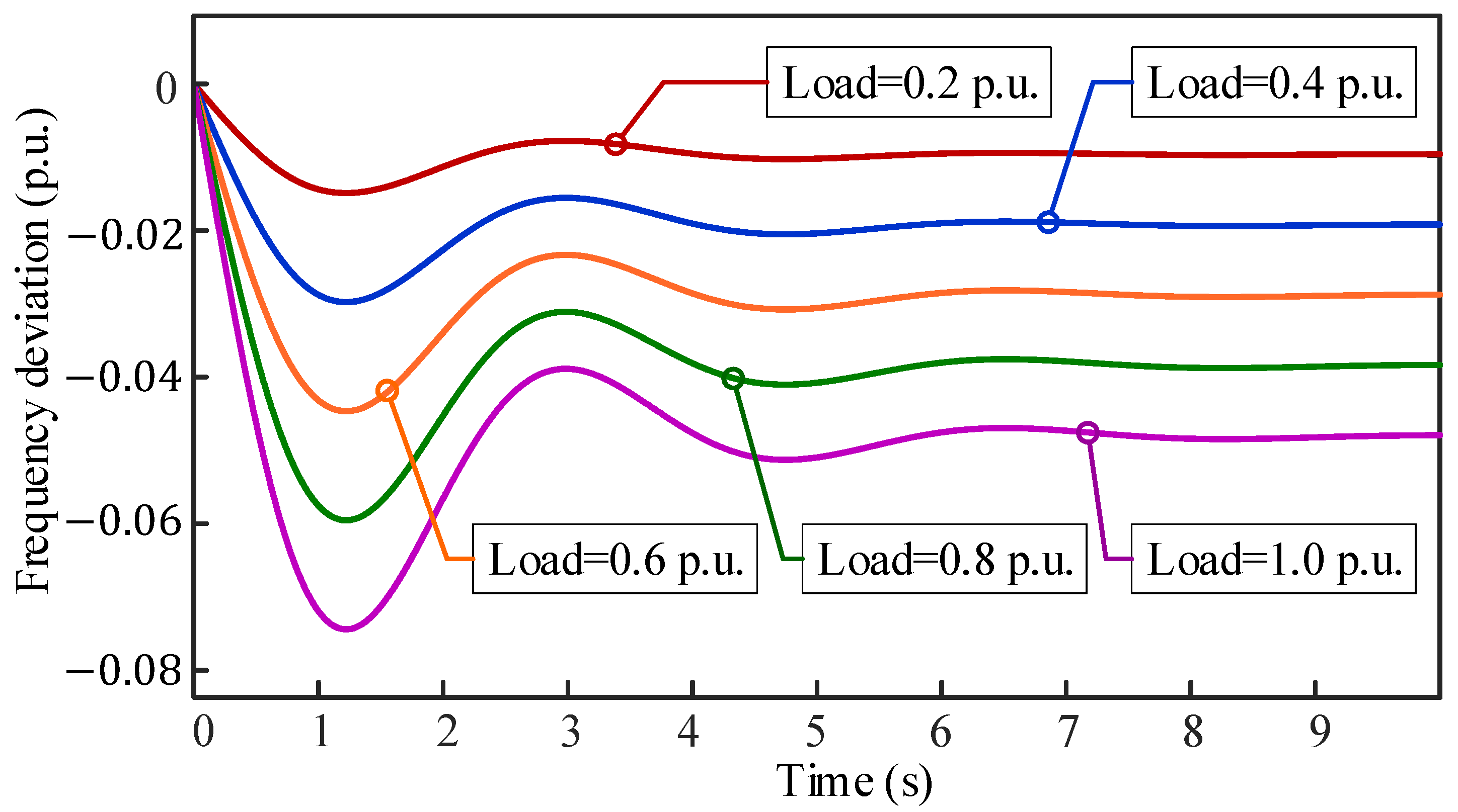
The power system frequency fluctuates as a result of variations in load. The impact of changing the load on an open-loop isolated power system’s frequency fluctuation is illustrated in Figure 2. It is notable from Figure 2 that, in an open-loop scenario, the frequency fluctuation varies according to the load applied. So, it is expected to mitigate the frequency deviation of single-area power system using a closed-loop control strategy. This is the main motivation of the work.
3. Design of the Proposed Controller
The design of the proposed controller has three steps. Firstly, the LQR has to be designed. After that, the proportional damping compensator will be designed. Finally, the LQR has to be integrated with the proportional damping compensator to obtain the proposed controller.
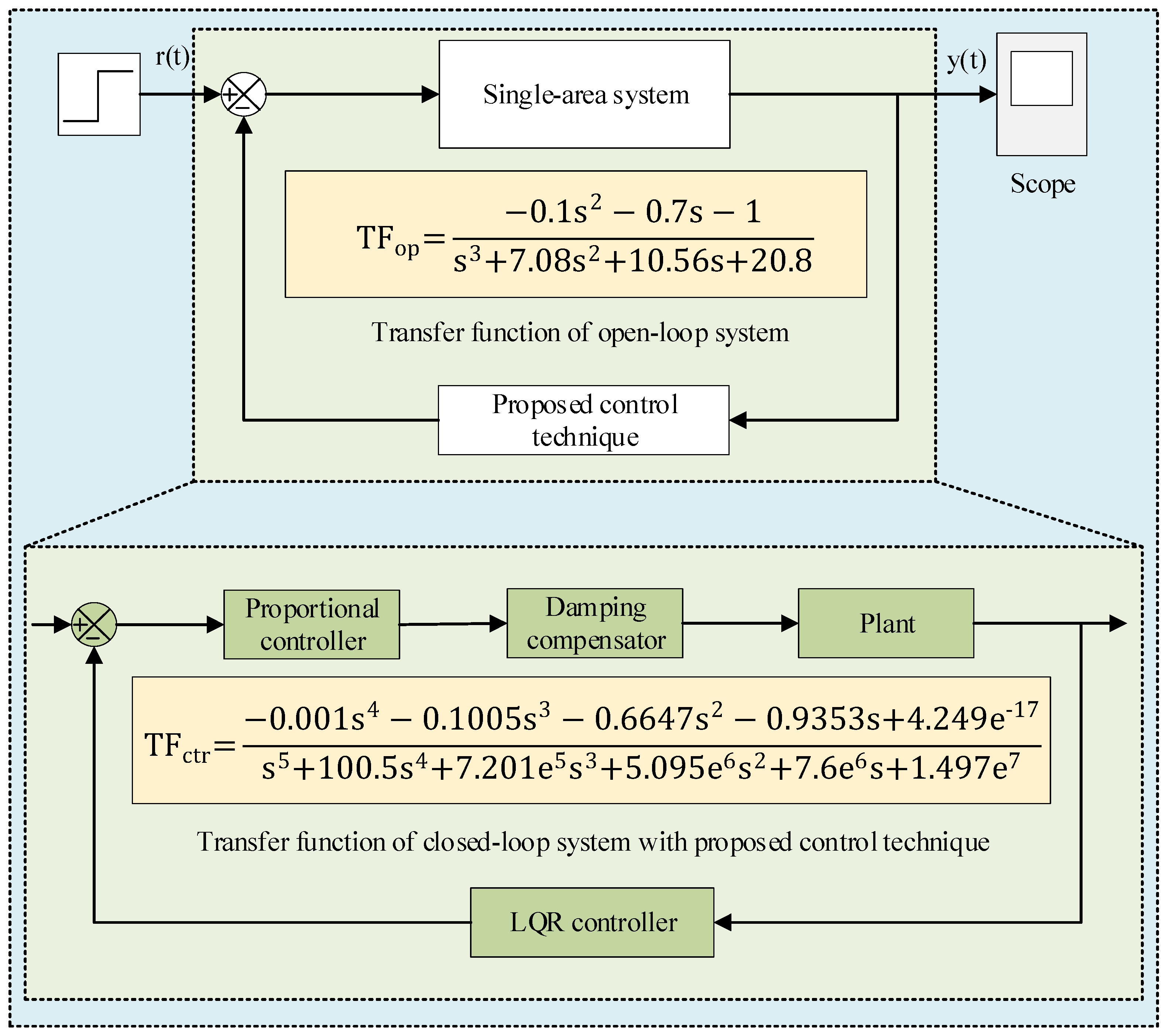
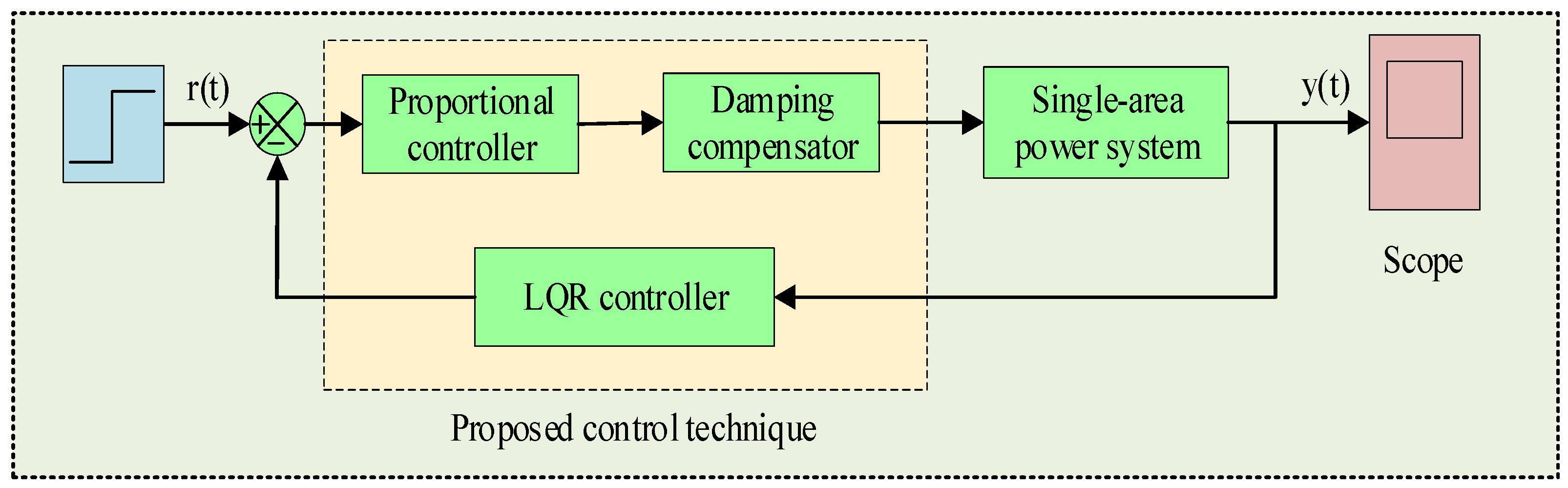
Figure 3 depicts the mathematical development of the proposed control technique for a single-area power system. In the proposed technique, the LQR controller is connected in a feedback loop. Both the proportional controller and damping compensator are connected in a series with the plant. Integrating the LQR with the proportional controller and damping compensator forms the proposed controller which significantly improves the system response in terms of frequency deviation, settling time, and steady-state error.
3.1. Design of the LQR
The LQR controller is an idealized control regulator that considers an appropriate control law to minimize a quadratic objective function while enhancing system dynamics by using a feedback gain. It uses a set of linear differential equations to model system dynamics, and the performance indicator is provided by a quadratic function, hence the name LQR. The single-area plant can be described as follows:
where, is the state vector’s derivation and U(t), and Y(t) are input and output vectors, respectively, and the ranges are , , and .
For LQR controller, the quadric objective function is mentioned below.
The value of P and K is established through the appropriate selection of the Q and R matrices where Q is state-weighting matrix and R is the control-weighting matrix. The selection of the Q and R matrices during the LQR design process is crucial and is determined by the control objectives and system characteristics. Tuning the values of Q and R matrices typically involves trial and error, engineering discretion, and system knowledge. Matrix A is the state matrix of order , matrix B is the input matrix of order , C and D are the output matrix of order , and feedforward matrix of order respectively. The values of the above-mentioned matrix for this plant are
Matrix D is considered a zero-matrix due to the absence of a direct feedforward mechanism. The value of K(t) significantly affects the output of the load frequency control. The roots of the system will be positioned in the most precise location with the assistance of LQR. Thus, by minimizing a cost function, the LQR controller provides optimal performance, ensuring a rapid response to load changes and stable frequency regulation. It provides disturbance resistance and maintains stable frequency regulation even in the presence of uncertainty. The LQR controller is adaptable and flexible, allowing for simple tuning to satisfy specific control objectives and system requirements in load frequency control.
3.2. Design of the Proportional Damping Compensator
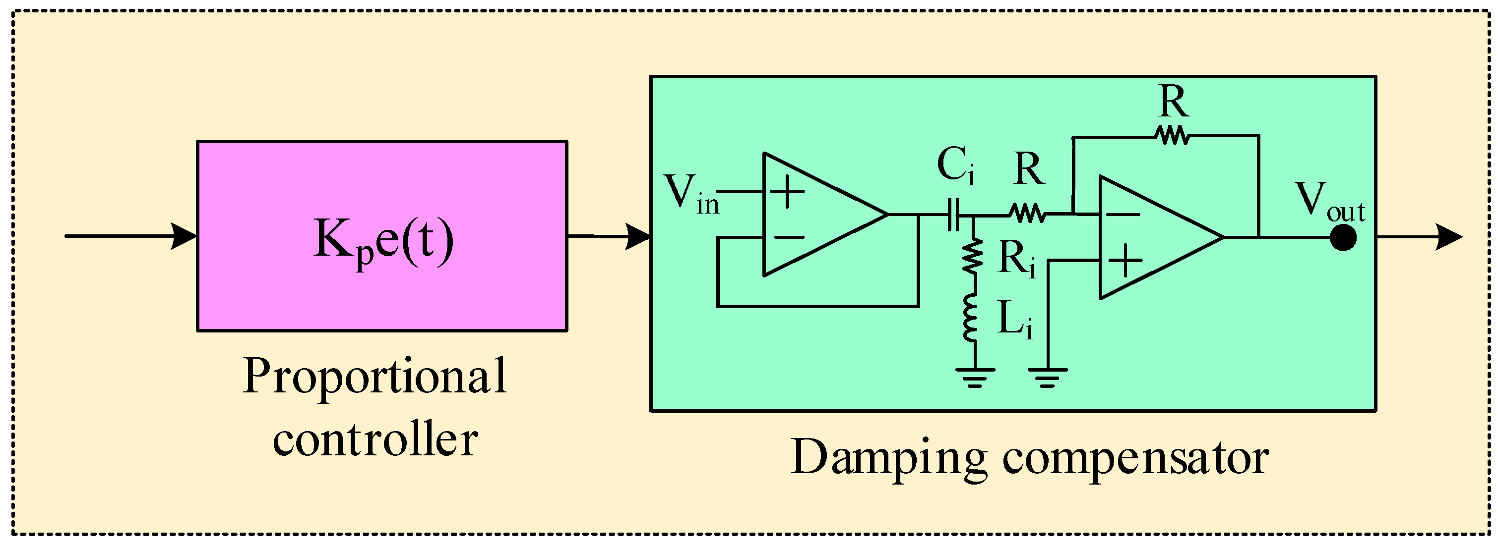
A damping compensator is a control mechanism used in power systems to improve the stability of the system by providing additional damping to oscillations. Figure 4 shows the proportional damping compensator where the op-amp structure of a basic damping compensator is connected in a series with the proportional controller.
In the majority of instances, the compensator is designed as a feedback control loop that modifies the power system’s parameters in response to shifting system conditions. The transfer function of a damping compensator is provided as follows:
The LFC loop can be improved by selecting proper values for the resistor (Ri), capacitor (Ci), and inductor (Li). To analyze the effects of the resistor, capacitor, and inductor, three compensators are considered with different values for Ri, Ci, and Li [28].
3.3. Integrating the LQR with Proportional Damping Compensator
The proportional (P) controller is a form of feedback controller that modifies the output based on the discrepancy between the actual and target system frequency and the damping compensator’s goal is to increase the system’s damping ratio, which is a gauge of its capacity to withstand oscillations and return to its stable equilibrium condition following a disturbance. To improve the stability and performance of the system and the further development of the performance of the control technique, a proportional controller is incorporated with a proportional damping compensator along with the LQR.
In the proposed control technique, the proportional compensator and the damping compensator are connected in a series but the LQR is incorporated as a feedback loop as depicted in Figure 5. The transfer function of the open-loop system is given as
By combining the benefits of the LQR, P-controller, and the damping compensator, the proposed controller is formed.
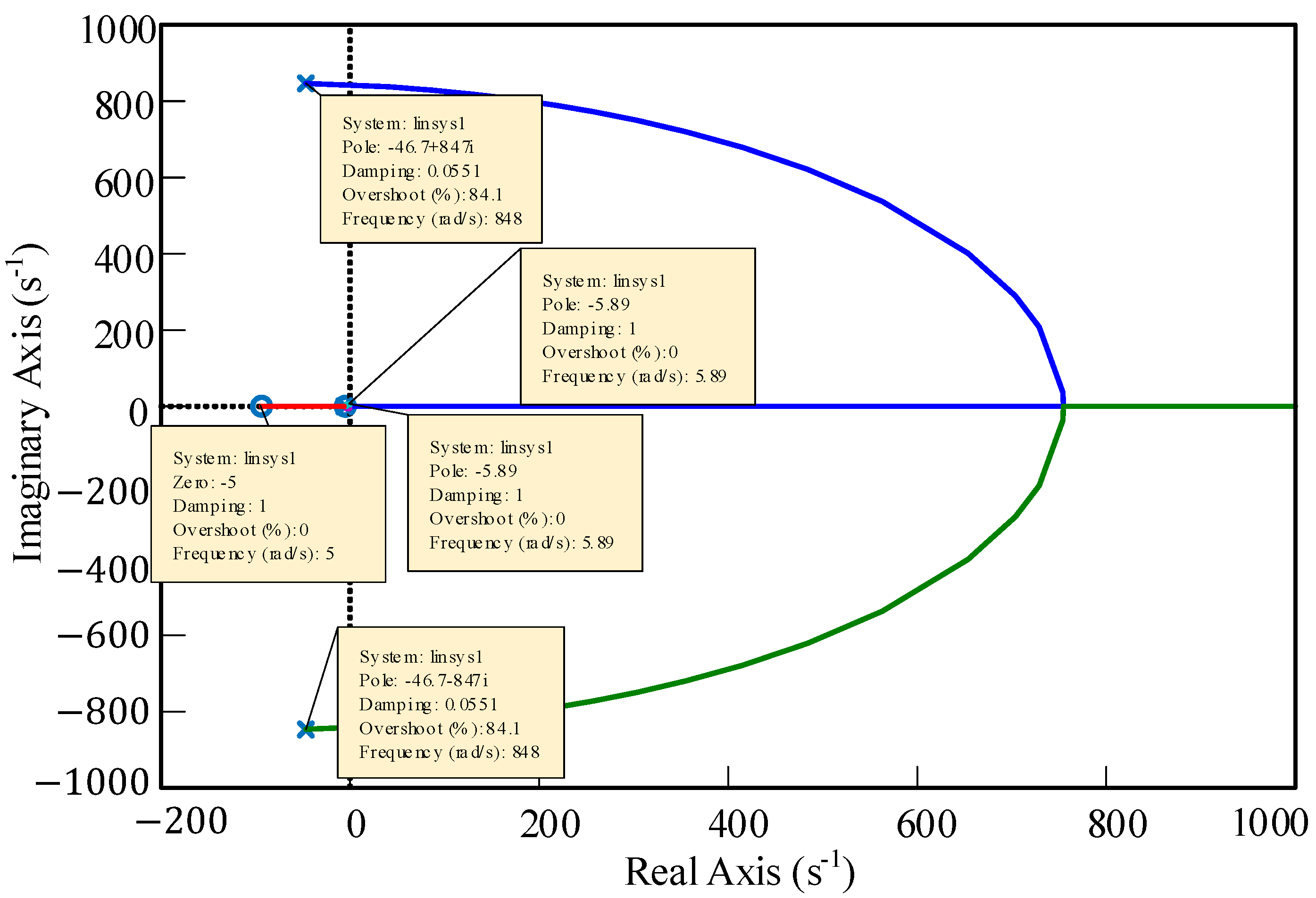
It has been demonstrated that using the LQR-based proportional damping compensator in LFC boosts transient performance, dampens frequency oscillations better, and increases robustness to changes in load and system parameters. Figure 6 shows the root locus diagram of a closed-loop system with a proposed control technique. The figure shows that the poles and zeros of the closed-loop system lie on the left side of the real axis which indicates the system’s stability. The transfer function of the closed-loop single-area power system with proposed control technique is calculated.
4. Simulation Results Analysis
4.1. Response of the Single-Area Power System with LQR
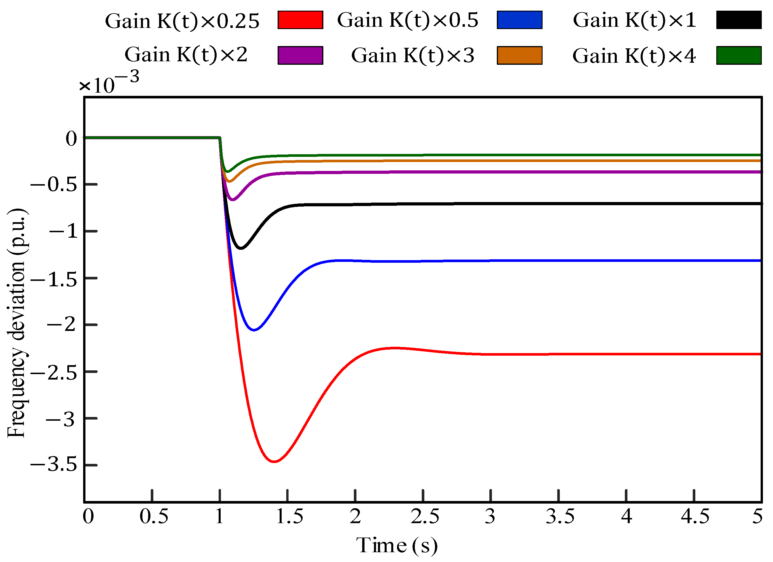
Figure 7 depicts the response of the single-area power system with LQR controller only. The gain, K(t), is varied for obtaining the result of Figure 7. It is noticed from Figure 7 that the frequency deviation is highest at gain = K(t) 0.25 and lowest at for gain = K(t) 4.
As can be also seen from Figure 7, increasing the feedback gain in an LQR controller can enhance the system’s tracking performance, response time, and overshoot. Nevertheless, increasing the feedback gain can also increase the system’s sensitivity to disturbances and noise, leading to instability and oscillations.
4.2. Response of the Single-Area Power System with LQR and Damping Compensator
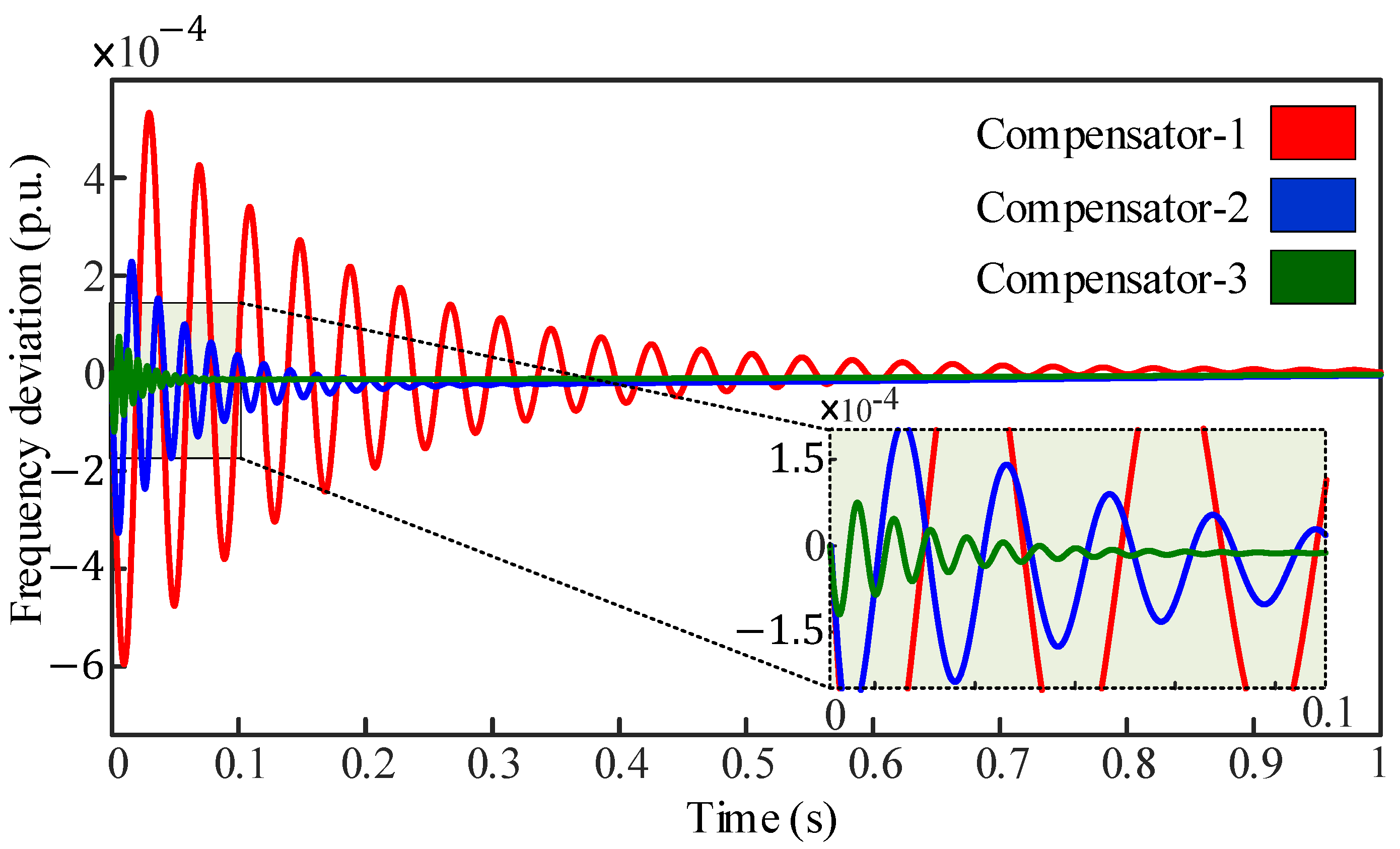
To investigate the response of the single-area power system with the LQR-integrated damping compensator, three different compensators are considered here. These are compensator-1, compensator-2, and compensator-3, based on Equation (17). The transfer function of these compensators is
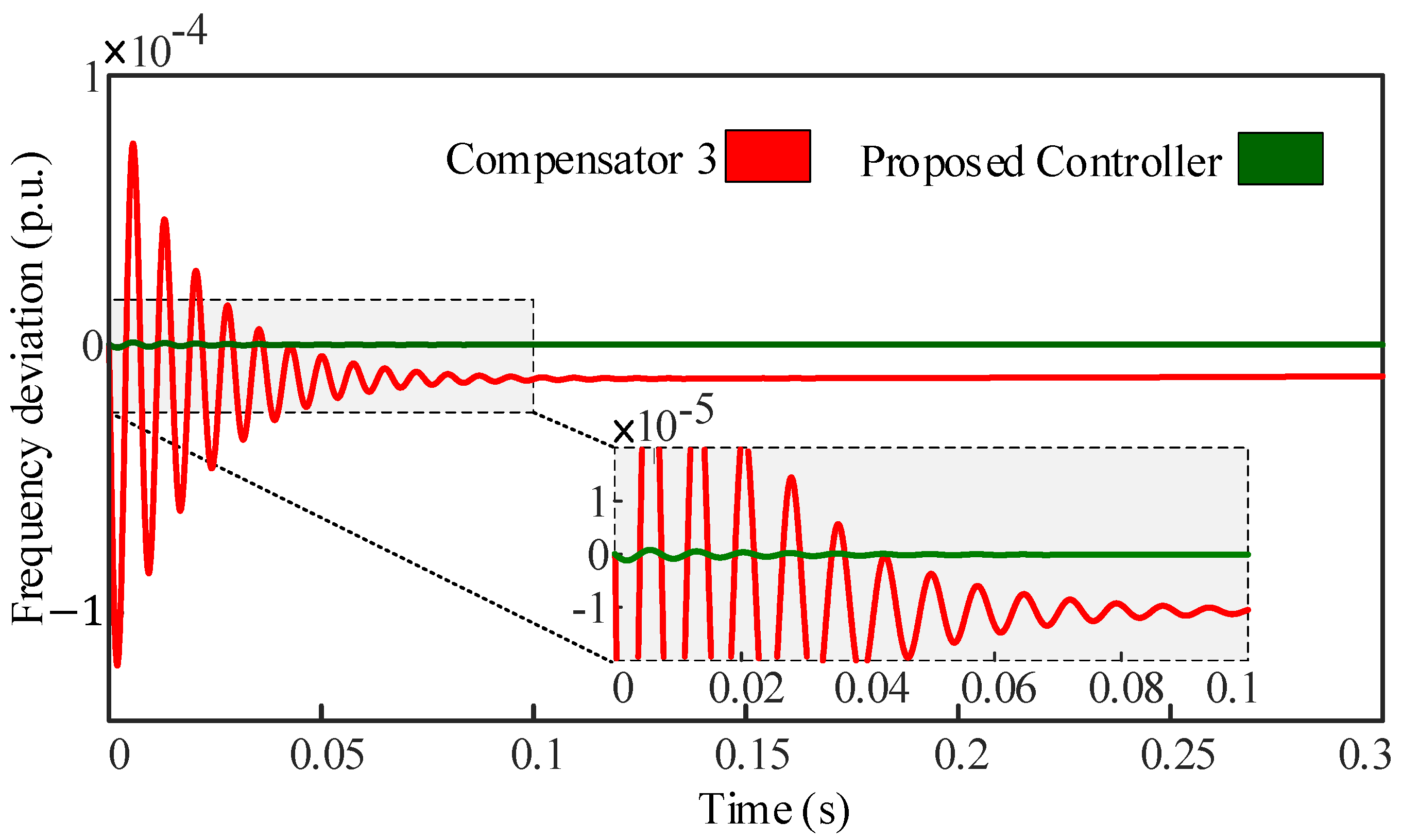
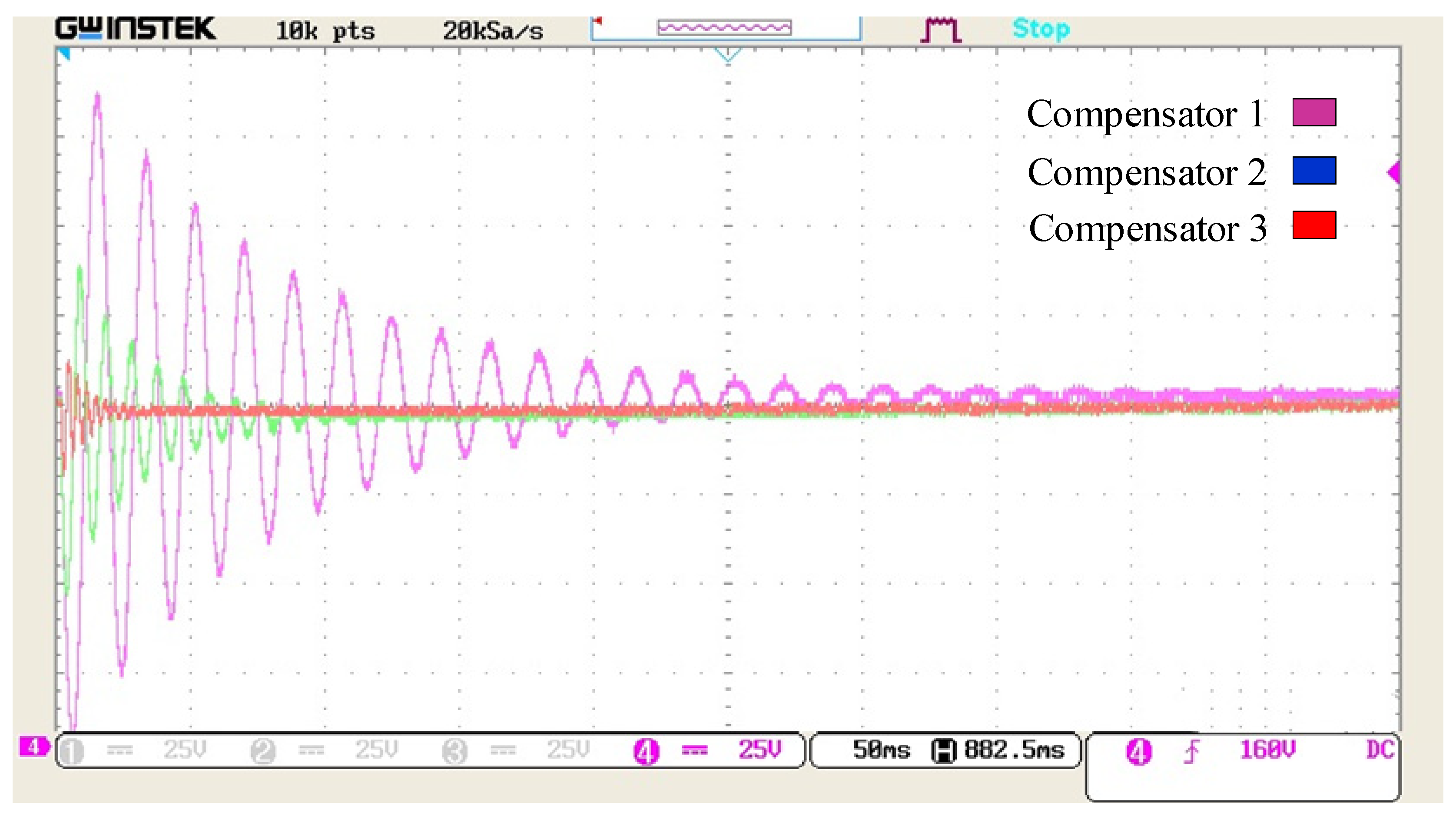
Figure 8 shows the performance of all three compensators integrated with LQR in an isolated LFC area for 1 p.u. of the load applied at t = 0 s. From Figure 8, it can be seen that compensator-3 shows better performance in terms of both frequency deviation and settling time compared to the other two compensators. The frequency deviation of compensator-3 is significantly less and the required settling time is smaller than the rest of the compensators.
4.3. Response of the Single-Area Power System with the Proposed LQR-based Proportional Damping Compensator
For the single-area power system of Figure 1, a series of simulations are conducted to analyze the LFC for both open-loop and closed-loop conditions, and a new control technique is proposed, named as the LQR-based proportional damping compensator. Figure 9 displays the performance of both the proposed controller and compensator-3, where 1 p.u. of the load variation is applied at time t = 0 s. In terms of frequency deviation and steady-state error, the proposed controller exhibits substantially superior performance, as cleared from Figure 9.
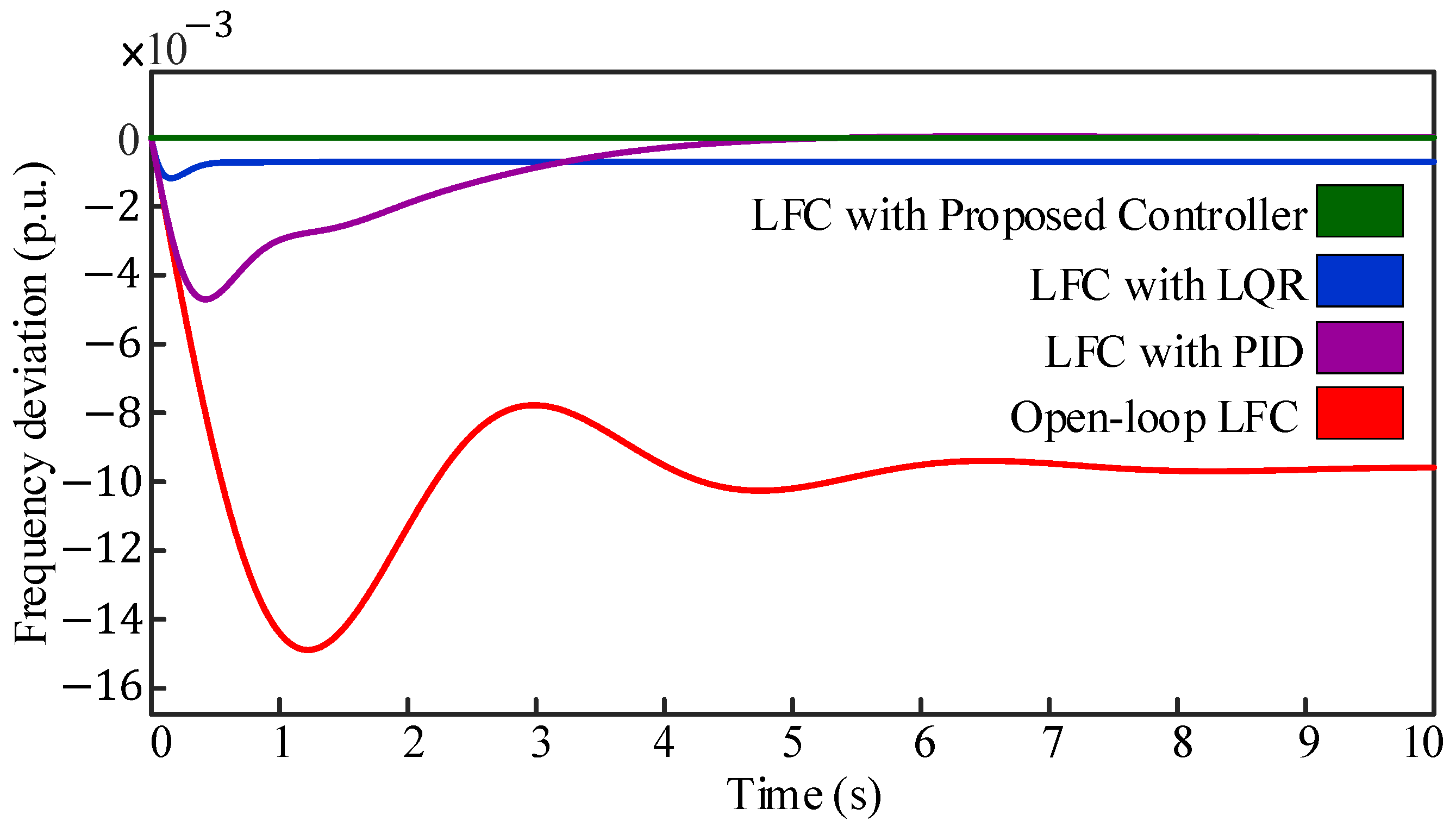
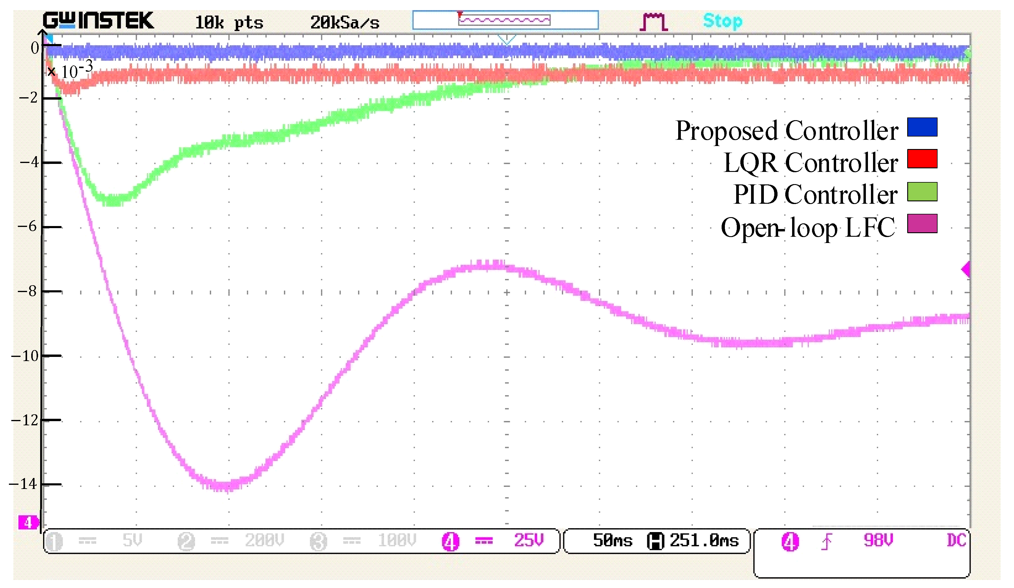
For the closed-loop condition, multiple control techniques including the LQR-based proportional damping compensator are implemented on the single-area network. Figure 10 contrasts the open-loop, PID, LQR, and proposed controller by depicting the frequency deviation of the single-area power system for 1 p.u. of the load variation at time t = 0 s.
Figure 10 demonstrates that an open-loop system exhibits the highest steady-state error for sudden load variation, which results in a considerable loss of power and an extended recovery period of up to 10 s for the system to regain stability. Implementation of the PID controller reduces the steady-state error to zero. However, compared to other controllers, the PID does not perform adequately in terms of frequency deviation and settling time. On the other hand, the LQR shows better performance for all the three parameters: frequency deviation, settling time, and steady-state error. With a p.u. steady-state error, the LQR needs only approximately 0.7 s to stabilize the system. Among the mentioned controller techniques, the proposed controller shows significantly better performance in terms of frequency deviation, settling time, and steady-state error. With only 0.15 s required for settling time, the proposed controller has only p.u. of steady-state error and p.u. of frequency deviation after a sudden load application. Table 1 compares the performance of different controllers in a single-area power system according to various performance parameters.
Form Table 1, it is seen that for frequency deviation, the proposed controller has the minimum value which indicates better performance. The fluctuation in the frequency due to sudden load variation is lower for the LQR-based proportional damping compensator.
Similarly, the proposed controller has a significantly lower settling time which indicates that a sudden load application system takes a comparatively short duration of time to regain its stability. A conventional controller such as the PID needs approximately 6 s and an optimal controller such as the LQR needs 0.7 s to stabilize the system, but the proposed controller needs only 0.15 s which is substantially lower than the PID and LQR. In addition, the steady-state error for the proposed controller is lower among all the above-mentioned controllers except for the PID. Although the PID has a steady-state error of zero, its other parameters, such as frequency deviation and steady-state error, are substantially greater than those of the proposed controller. The proposed controller significantly enhances the frequency response, stability, and transient performance of the system, and the steady-state error is reduced to per unit. Compared to the PID, LQR, and Legendre functions, the proposed controller exhibits a minimal frequency deviation and requires the shortest settling time. The proposed controller outperforms the aforementioned control techniques in terms of frequency deviation, settling time, and steady-state error, as shown in Table 1.
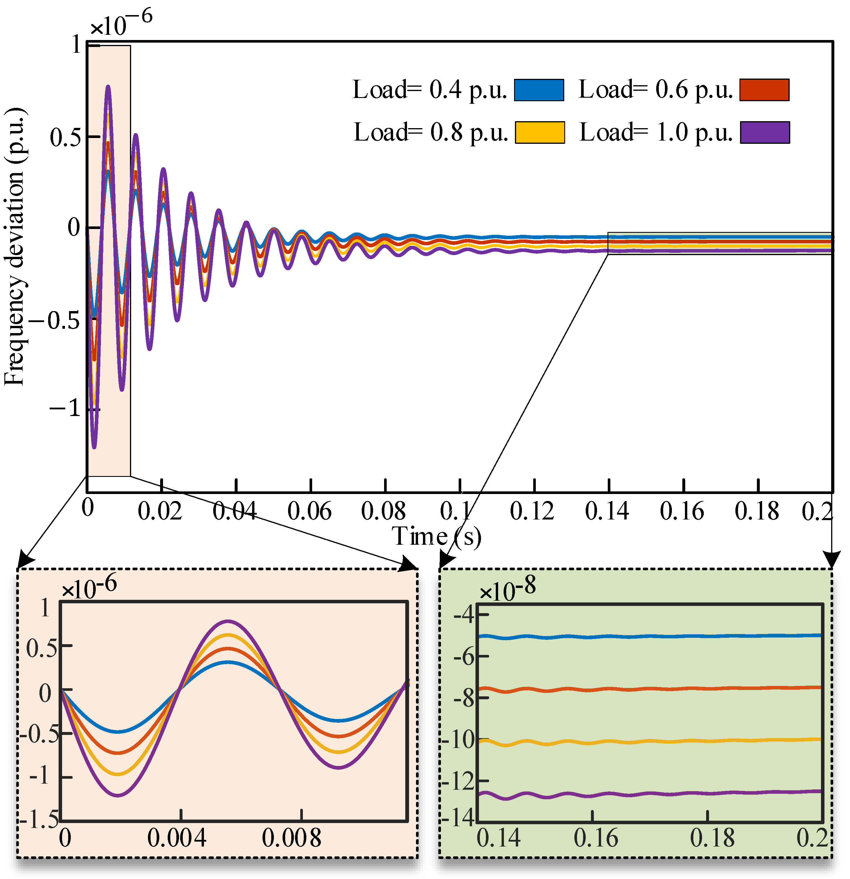
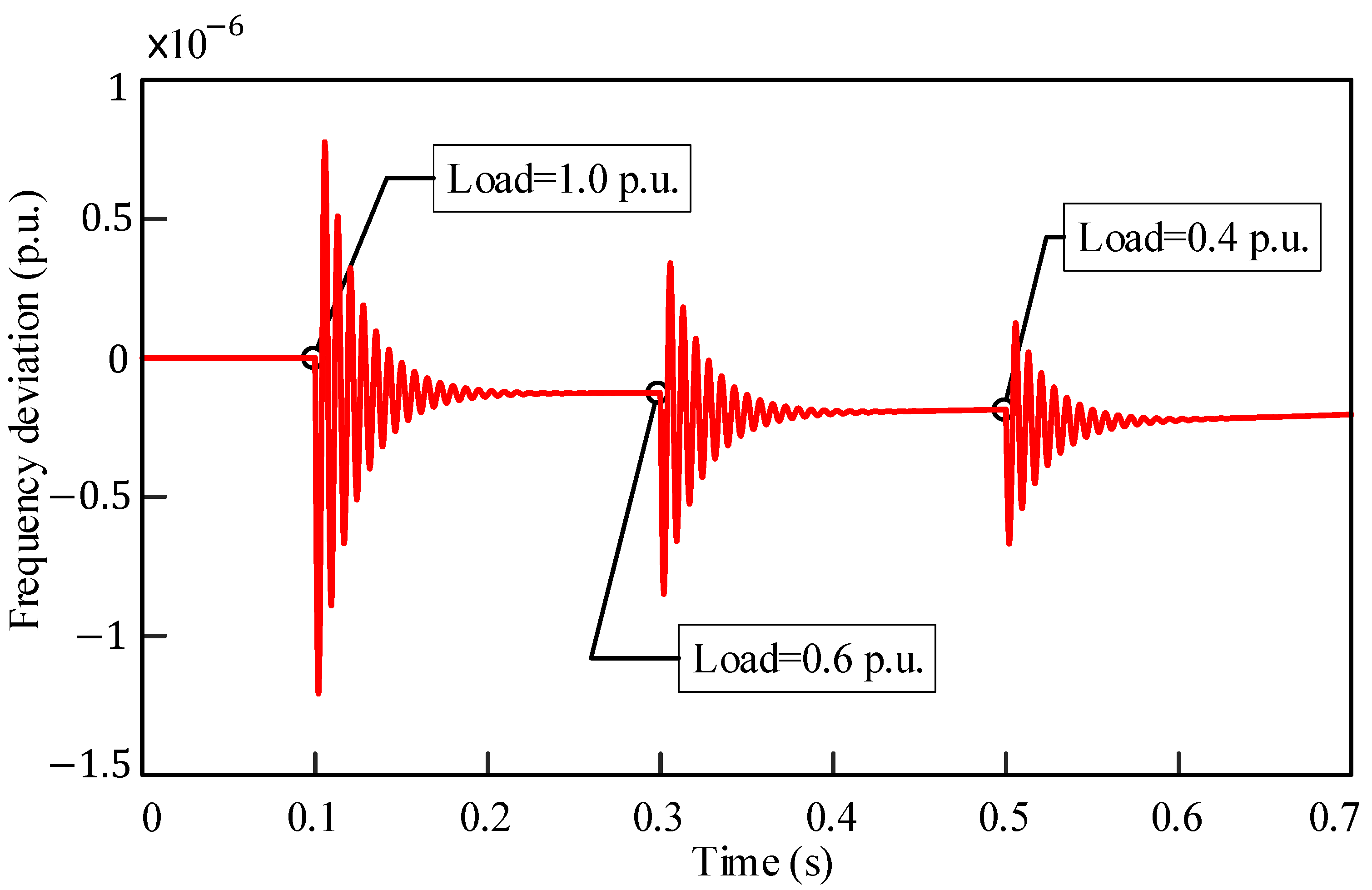
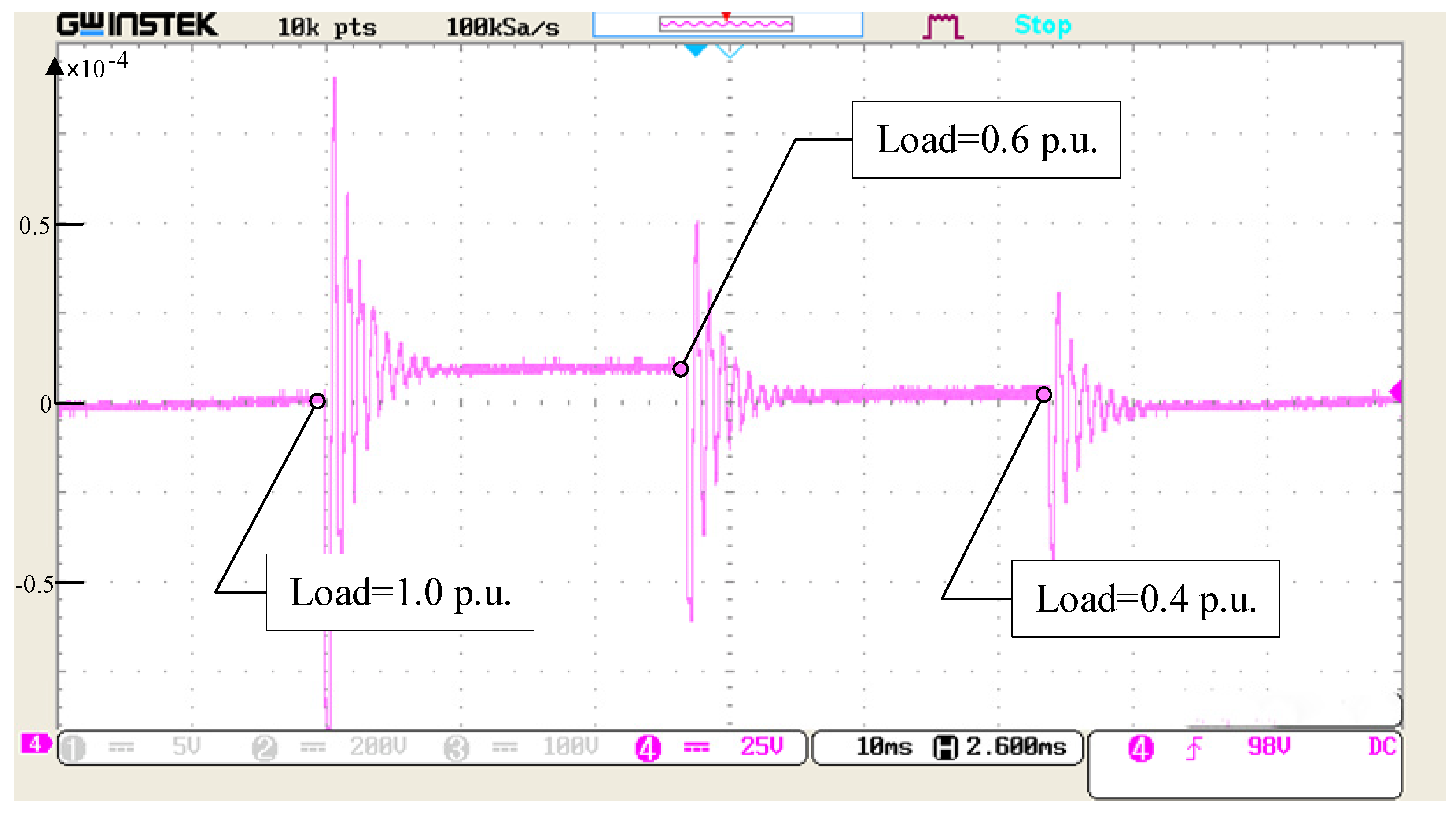
To evaluate the performance of the proposed controller, additional simulations are conducted under various conditions. Figure 11 presents the combined results for the frequency control of the proposed controller in several single-area power systems for various load implementations at time t = 0 s. The applied load varied from 0.4 p.u. to 1.0 p.u. for several systems and merged in one figure, and as the load variation increased, the required time to regain stability increased marginally. In addition, as the load variation increased, the steady-state error increased slightly, but the performance of the proposed controller is significantly preferable than other above-mentioned controllers. In Figure 12, variable loads are administered at various times to a single-area system. At time 0.1 s, 0.3 s, and 0.5 s, loads of 1.0 p.u., 0.6 p.u., and 0.4 p.u., are applied accordingly. Within a timeframe of 0.7 s, three sudden load variations are applied, but the system regained stability 0.15 s after each load application. Variation in frequency depends on the amount of load applied on the system. Thus, it can be seen that the performance of the proposed controller, the proposed LQR-based proportional damping compensator, is more compatible for a single-area power system than conventional controllers.
5. Experimental Analysis
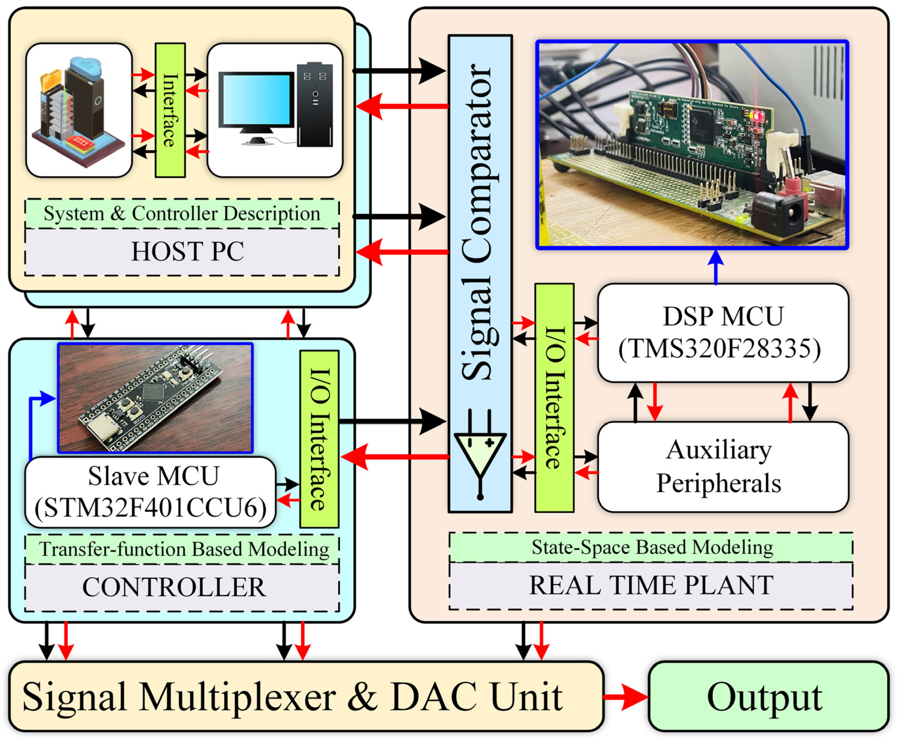
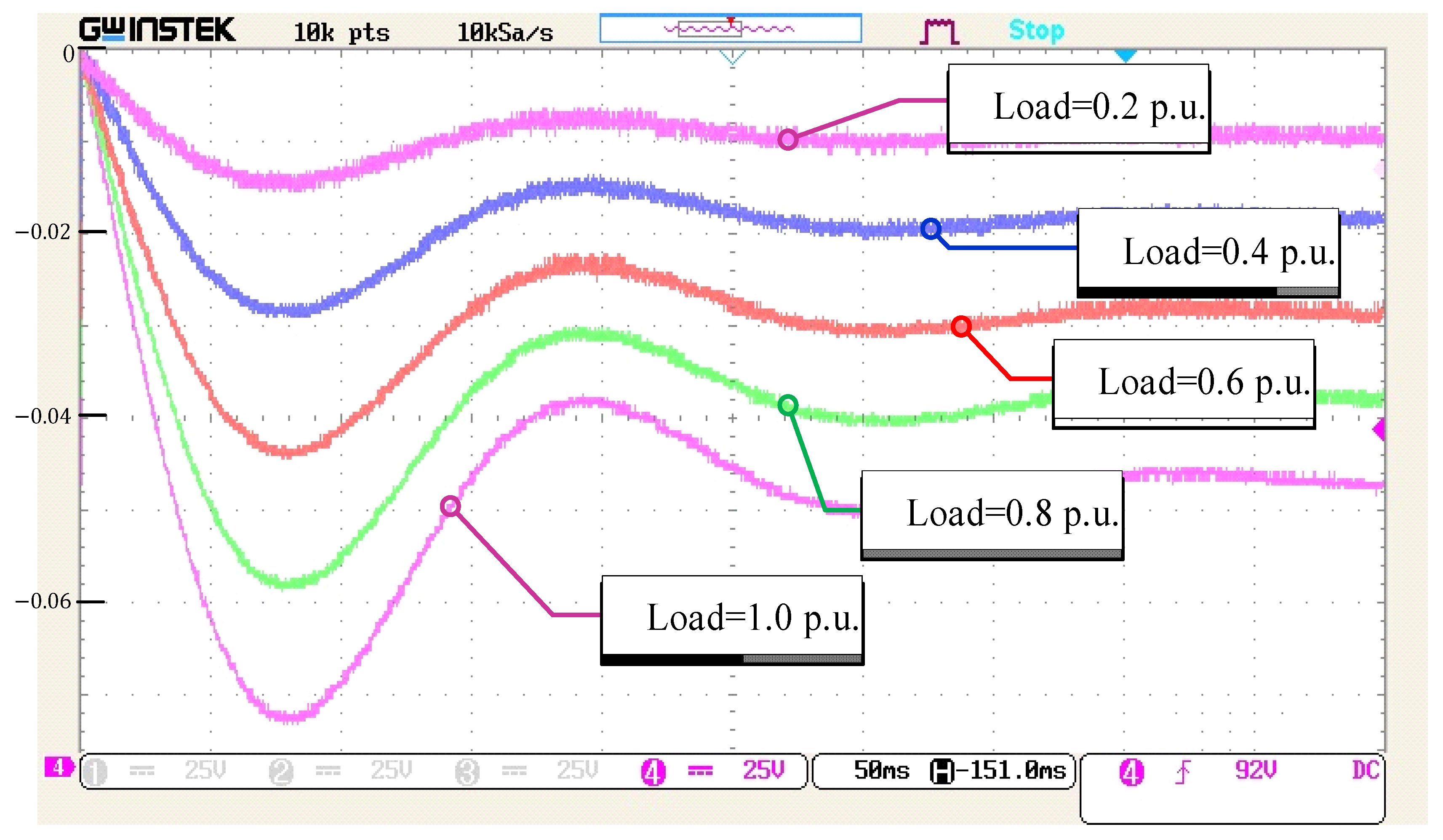
To validate the performance of the proposed controller, a hybrid multiprocessor-based processor-in-loop (PIL) technique is introduced. The presented technique is different from traditional PIL techniques as the presented PIL technique employs multiple single microcontroller units (MCUs) for conducting individual tasks during real-time simulation. The complete setup of the hybrid multiprocessor-based processor-in-loop (PIL) technique is depicted in Figure 10. The step-by-step implementation procedure is described here. At first, the plant model is deployed in TMS320F28335 DSP MCU. The state-space model of the plant is built in MATLAB/Simulink software environment. After that, the corresponding mathematical model is transferred to a code composer studio-integrated development environment (CCS-IDE) and finally deployed to the TMS320F28335 DSP MCU. Secondly, the proposed controller as well as other existing controllers are implemented utilizing slave MCU as depicted in Figure 13. STM32F401CCU6 MCU is chosen as the slave which is connected to the host PC and real-time plant system through the I2C communication protocol. Finally, the digital responses of the plant and controllers are converted into analog signals through a digital to analog converter (DAC) interface. The performances of the plant and controllers are captured through a GDS1104B 4-channel digital oscilloscope from the DAC output terminals. The frequency fluctuation response against different load conditions for a single-area power system is shown in Figure 14. From Figure 14, it is clear that different loads have been applied on the single-area power system which leads to a frequency fluctuation at open-loop conditions. The experimental result of Figure 13 complies well with the simulated result of Figure 2. The frequency deviation response of three different existing LQR-based compensators is depicted in Figure 15. The experimental result of Figure 15 agrees well with the simulation result of Figure 8. The frequency deviation response of Figure 16 shows the frequency variation for the open loop, PID, LQR, and the proposed controller, while a step change of load is applied on the system. From Figure 16, it is clear that the proposed controller takes the minimum time to recover from the transient period as compared to the open loop, PID, and LQR. The simulation result of Figure 10 is similar to the experimental result of Figure 16. The dynamic load variation response of the proposed controller is shown in Figure 17. Three different loads have been applied at different time instants as cleared from Figure 17 which is similar to the simulation result of Figure 12. The proposed controller tries to recover the load transient quickly. From the experimental findings, it is evident that the responses of the different existing and proposed controllers coincide with the simulation results.
6. Conclusions
In this work, a new control technique for mitigating the frequency fluctuation in a single-area power system has been proposed. The proposed LQR-based proportional damping compensator outperforms the LQR, PID, and open-loop system. The simulation results demonstrate that the proposed controller can effectively mitigate frequency fluctuation and maintain the system frequency within acceptable limits. The system’s transient response and steady-state performance have been significantly improved in terms of frequency deviation, settling time, and steady-state error. By using the proposed controller, for 1 p.u. of the load variation, the settling time is 0.15 s and the steady-state error is p.u., which are significantly better than those of the LQR and PID controller. Apart from simulation analysis, a hybrid multiprocessor-based PIL technique is introduced in this paper to validate the real-time feasibility of the proposed control technique. A good agreement among the mathematical analysis, simulated performance analysis, and experimental results has validated the feasibility and contributions of the proposed control technique.
Author Contributions
Conceptualization, P.D. and S.P.B.; methodology, P.D. and M.R.I.; software, P.D. and S.P.B.; validation, S.M. and M.R.I. formal analysis, S.P.B.; investigation, M.R.I.; resources, S.P.B.; data curation, P.D. and S.M.; writing—original draft preparation, P.D., S.P.B. and S.M.; writing—review and editing, S.M. and S.P.B.; visualization, P.D. and S.P.B.; supervision, S.P.B.; project administration, M.R.I.; funding acquisition, M.R.I. All authors have read and agreed to the published version of the manuscript.
Funding
This research received no external funding.
Data Availability Statement
Not applicable.
Conflicts of Interest
The authors declare no conflict of interest.
Nomenclature
| τg | is the time constant of the governor; |
| τT | is the time constant of the turbine; |
| ΔPref | is the reference set power; |
| Δfd | is the frequency deviation; |
| ΔPL | is the load variation; |
| H | is the governor inertia constant; |
| D | is the frequency sensitive load coefficient; |
| R | is the speed regulation of the governor; |
| Abbreviations | |
| LFC | Load frequency control |
| AGC | Automatic generation control |
| PIL | Processor-in-loop |
| LQR | Linear quadratic regulator |
| SG | Synchronous generator |
| PID | Proportional–integral–derivative |
| MPC | Model predictive control |
| SMC | Sliding mode control |
| ANN | Artificial neural networks |
| EID | Equivalent input disturbances |
| ADRC | Active disturbance rejection control |
| SOPTD | Second order plus time delay |
| FOPID | Fractional-order proportional–integral–derivative |
References
- Fusco, G.; Russo, M. Adaptive voltage regulator design for synchronous generator. IEEE Trans. Energy Convers. 2008, 23, 946–956. [Google Scholar] [CrossRef]
- Rajamand, S. Load Frequency Control and Dynamic Response Improvement Using Energy Storage and Modeling of Uncertainty in Renewable Distributed Generators. J. Energy Storage 2021, 37, 102467. [Google Scholar] [CrossRef]
- Tan, K.M.; Babu, T.S.; Ramachandaramurthy, V.K.; Kasinathan, P.; Solanki, S.G.; Raveendran, S.K. Empowering smart grid: A comprehensive review of energy storage technology and application with Renewable Energy Integration. J. Energy Storage 2021, 39, 102591. [Google Scholar] [CrossRef]
- Ranjan, M.; Shankar, R. A literature survey on load frequency control considering renewable energy integration in power system: Recent trends and future prospects. J. Energy Storage 2022, 45, 103717. [Google Scholar] [CrossRef]
- Dokht Shakibjoo, A.; Moradzadeh, M.; Moussavi, S.Z.; Vandevelde, L. A novel technique for load frequency control of Multi-Area Power Systems. Energies 2020, 13, 2125. [Google Scholar] [CrossRef]
- Pandey, S.K.; Gupta, P.; Dwivedi, S.S. Full order observer-based load frequency control of Single Area Power System. In Proceedings of the 2020 12th International Conference on Computational Intelligence and Communication Networks (CICN), Bhimtal, India, 25–26 September 2020. [Google Scholar]
- Dehuri, P.; Hote, Y.V. Indirect IMC based PID controller design for single area LFC system in the presence of uncertainty and communication delay. In Proceedings of the 2021 IEEE Texas Power and Energy Conference (TPEC), College Station, TX, USA, 2–5 February 2021. [Google Scholar]
- Khan, M.; Sun, H. Complete Provision of MPC-Based LFC By Electric Vehicles With Inertial and Droop Support from DFIG-Based Wind Farm. IEEE Trans. Power Deliv. 2022, 37, 716–726. [Google Scholar] [CrossRef]
- Zhong, Q.; Yang, J.; Shi, K.; Zhong, S.; Li, Z.; Sotelo, M.A. Event-Triggered H∞ Load Frequency Control for Multi-Area Nonlinear Power Systems Based on Non-Fragile Proportional Integral Control Strategy. IEEE Trans. Intell. Transp. Syst. 2022, 23, 12191–12201. [Google Scholar] [CrossRef]
- Ali, H.H.; Fathy, A.; Al-Shaalan, A.M.; Kassem, A.M.; Farh, H.M.H.; Al-Shamma’a, A.A.; Gabbar, H.A. A novel sooty terns algorithm for deregulated MPC-LFC installed in multi-interconnected system with renewable energy plants. Energies 2021, 14, 5393. [Google Scholar] [CrossRef]
- Mercader, P.; Åström, K.J.; Baños, A.; Hägglund, T. Robust PID Design Based on QFT and Conve Concave Optimization. IEEE Trans. Control. Syst. Technol. 2017, 25, 441–452. [Google Scholar] [CrossRef]
- Chen, B.-Y.; Shangguan, X.-C.; Jin, L.; Li, D.-Y. An improved stability criterion for load frequency control of power systems with time-varying delays. Energies 2020, 13, 2101. [Google Scholar] [CrossRef] [Green Version]
- Liu, F.; Zhang, K.; Zou, R. Robust LFC Strategy for Wind Integrated Time-Delay Power System Using EID Compensation. Energies 2019, 12, 3223. [Google Scholar] [CrossRef] [Green Version]
- Kumar, A.; Pan, S. Design of fractional order PID controller for load frequency control system with communication delay. ISA Trans. 2022, 129, 138–149. [Google Scholar] [CrossRef]
- Alayi, R.; Zishan, F.; Seyednouri, S.R.; Kumar, R.; Ahmadi, M.H.; Sharifpur, M. Optimal load frequency control of island microgrids via a PID controller in the presence of wind turbine and PV. Sustainability 2021, 13, 10728. [Google Scholar] [CrossRef]
- Liu, X.; Qiao, S.; Liu, Z. A survey on load frequency control of multi-area power systems: Recent challenges and Strategies. Energies 2023, 16, 2323. [Google Scholar] [CrossRef]
- Yerolla, R.; Bestha, C.S. PI/PID controller design for critically damped SOPTD system and experimental validation. In Proceedings of the 2021 5th International Conference on Intelligent Computing and Control Systems, Madurai, India, 6–8 May 2021; pp. 531–535. [Google Scholar]
- Mani, P.; Joo, Y.H. Fuzzy logic-based integral sliding mode control of multi-area power systems integrated with wind farms. Inf. Sci. 2021, 545, 153–169. [Google Scholar] [CrossRef]
- Liu, X.; Bai, D.; Qiao, S.; Xiao, G.; Ge, S.S. Resilient and event-triggered sliding mode load frequency control for multi-area power systems under hybrid cyber attacks. IET Control Theory Appl. 2022, 16, 1739–1750. [Google Scholar] [CrossRef]
- Sun, Y.; Wang, Y.; Wei, Z.; Sun, Z.; Wu, X. Robust H∞ load frequency control of multi-area power system with time delay: A sliding mode control approach. IEEE/CAA J. Autom. Sin. 2017, 5, 610–617. [Google Scholar] [CrossRef]
- Hossam-Eldin, A.; Mostafa, H.; Kotb, H.; AboRas, K.M.; Selim, A.; Kamel, S. Improving the frequency response of hybrid microgrid under renewable sources’ uncertainties using a robust LFC-based African vulture optimization algorithm. Processes 2022, 10, 2320. [Google Scholar] [CrossRef]
- Coban, H.H.; Rehman, A.; Mousa, M. Load frequency control of microgrid system by battery and pumped-hydro energy storage. Water 2022, 14, 1818. [Google Scholar] [CrossRef]
- Alaei, H.K.; Yazdizadeh, A.; Aliabadi, A. Nonlinear predictive controller design for load frequency control in power system using quasi newton optimization approach. In Proceedings of the IEEE International Conference on Control Applications (CCA), Hyderabad, India, 28–30 August 2013; pp. 679–684. [Google Scholar]
- Jamil, A.A.; Tu, W.F.; Ali, S.W.; Terriche, Y.; Guerrero, J.M. Fractional-order PID controllers for Temperature Control: A Review. Energies 2022, 15, 3800. [Google Scholar] [CrossRef]
- Ferahtia, S.; Djeroui, A.; Mesbahi, T.; Houari, A.; Zeghlache, S.; Rezk, H.; Paul, T. Optimal adaptive gain LQR-based Energy Management Strategy for Battery–Supercapacitor Hybrid Power System. Energies 2021, 14, 1660. [Google Scholar] [CrossRef]
- Sibilska-Mroziewicz, A.; Ordys, A.; Możaryn, J.; Alinaghi Hosseinabadi, P.; Soltani Sharif Abadi, A.; Pota, H. LQR and Fuzzy Logic Control for the three-area power system. Energies 2021, 14, 8522. [Google Scholar] [CrossRef]
- Tan, W.; Xu, Z. Robust analysis and design of Load Frequency Controller for Power Systems. Electr. Power Syst. Res. 2009, 79, 846–853. [Google Scholar] [CrossRef]
- Pota, H.R.; Moheimani, S.O.; Smith, M. Resonant controllers for smart structures. Smart Mater. Struct. 2002, 11, 1–8. [Google Scholar] [CrossRef]
Figure 1.
Modeling of the single-area power system.

Figure 2.
Frequency fluctuation in a single-area power system for different loads.

Figure 3.
Modeling of proposed LQR-based proportional damping compensator for a single-area power system.
Figure 3.
Modeling of proposed LQR-based proportional damping compensator for a single-area power system.

Figure 4.
Structure of the proportional damping compensator.

Figure 5.
Block representation of the proposed LQR-based proportional damping compensator for single-area power system.
Figure 5.
Block representation of the proposed LQR-based proportional damping compensator for single-area power system.

Figure 6.
Root locus of a single-area power system with the proposed LQR-based proportional damping compensator.
Figure 6.
Root locus of a single-area power system with the proposed LQR-based proportional damping compensator.

Figure 7.
Frequency fluctuation of single-area power system with LQR for different values of gain of the controller.
Figure 7.
Frequency fluctuation of single-area power system with LQR for different values of gain of the controller.

Figure 8.
Frequency fluctuations of compensator integrated with LQR of a single-area power system.

Figure 9.
Frequency deviation comparison between compensator-3 and the proposed controller for a single-area power system.
Figure 9.
Frequency deviation comparison between compensator-3 and the proposed controller for a single-area power system.

Figure 10.
Comparative frequency deviation analysis for different controllers of a single-area power system.
Figure 10.
Comparative frequency deviation analysis for different controllers of a single-area power system.

Figure 11.
Frequency deviation analysis for different loads on a single-area power system with the proposed controller.
Figure 11.
Frequency deviation analysis for different loads on a single-area power system with the proposed controller.

Figure 12.
Frequency deviation analysis for dynamic load variation on a single-area power system with the proposed controller.
Figure 12.
Frequency deviation analysis for dynamic load variation on a single-area power system with the proposed controller.

Figure 13.
Experimental test platform based on PIL.

Figure 14.
Experiment frequency fluctuation response against load variation for a single-area power system.
Figure 14.
Experiment frequency fluctuation response against load variation for a single-area power system.

Figure 15.
Experimental frequency fluctuation response of different existing LQR-integrated compensators for a single-area power system.
Figure 15.
Experimental frequency fluctuation response of different existing LQR-integrated compensators for a single-area power system.

Figure 16.
Experimental frequency fluctuation response: open loop, PID, LQR, and the proposed controller.
Figure 16.
Experimental frequency fluctuation response: open loop, PID, LQR, and the proposed controller.

Figure 17.
Experimental frequency deviation of the proposed controller against multiple load variation in a single-area power system.
Figure 17.
Experimental frequency deviation of the proposed controller against multiple load variation in a single-area power system.


Table 1.
Performance parameters of various controller for a single-area power system.
| Controller Technique | Frequency Deviation (p.u.) | Settling Time (s) | Steady-State Error (p.u.) |
|---|---|---|---|
| Open loop | 15 × 10−3 | 10 | 9.58 × 10⁻³ |
| PID [9] | 4.8 × 10⁻³ | 6 | 0 |
| LQR [10] | 11.9 × 10⁻⁴ | 0.7 | 7.052 × 10⁻⁴ |
| Legendre function [10] | 6 × 10⁻⁴ | 0.6 | 1 × 10⁻⁵ |
| Proposed controller | 2 × 10⁻⁶ | 0.15 | 2.83 × 10⁻⁷ |
Disclaimer/Publisher’s Note: The statements, opinions and data contained in all publications are solely those of the individual author(s) and contributor(s) and not of MDPI and/or the editor(s). MDPI and/or the editor(s) disclaim responsibility for any injury to people or property resulting from any ideas, methods, instructions or products referred to in the content. |
© 2023 by the authors. Licensee MDPI, Basel, Switzerland. This article is an open access article distributed under the terms and conditions of the Creative Commons Attribution (CC BY) license (https://creativecommons.org/licenses/by/4.0/).
Share and Cite
MDPI and ACS Style
Das, P.; Biswas, S.P.; Mondal, S.; Islam, M.R. Frequency Fluctuation Mitigation in a Single-Area Power System Using LQR-Based Proportional Damping Compensator. Energies 2023, 16, 4804. https://0-doi-org.brum.beds.ac.uk/10.3390/en16124804
AMA Style
Das P, Biswas SP, Mondal S, Islam MR. Frequency Fluctuation Mitigation in a Single-Area Power System Using LQR-Based Proportional Damping Compensator. Energies. 2023; 16(12):4804. https://0-doi-org.brum.beds.ac.uk/10.3390/en16124804
Chicago/Turabian StyleDas, Pranta, Shuvra Prokash Biswas, Sudipto Mondal, and Md Rabiul Islam. 2023. "Frequency Fluctuation Mitigation in a Single-Area Power System Using LQR-Based Proportional Damping Compensator" Energies 16, no. 12: 4804. https://0-doi-org.brum.beds.ac.uk/10.3390/en16124804
Note that from the first issue of 2016, this journal uses article numbers instead of page numbers. See further details here.