LADM Based Utility Network Cadastre in Serbia


Faculty of Technical Sciences, University of Novi Sad, 106314 Novi Sad, Serbia
*
Author to whom correspondence should be addressed.
ISPRS Int. J. Geo-Inf. 2019, 8(5), 206; https://0-doi-org.brum.beds.ac.uk/10.3390/ijgi8050206
Submission received: 8 March 2019
/
Revised: 15 April 2019
/
Accepted: 3 May 2019
/
Published: 6 May 2019
(This article belongs to the Special Issue Applications of GIScience for Land Administration)
Abstract
:The utility network cadastre in Serbia is the main register of utility lines and the rights to them. The Law on State Survey and Cadastre states the necessity for implementing a unified information system of both a real estate and utility network cadastre, but this has not been achieved in practice. The reasons for such a unified information system are to ensure easier maintenance of the rights of both the utilities and properties located above or below them, to ensure more efficient procedures for obtaining the consent for placement, repair, or removal of the utility line, to prevent procedures being executed based on outdated data, to build an information system as the law prescribes, and to facilitate the business processes in the Serbian geodetic authority, since it is responsible for both registers. Therefore, an already-developed LADM (Land Administration Domain Model)-based country profile for Serbia should be extended to include information from the utility network cadastre. An analysis of Serbian legislation showed the necessity of extending the class set of the utility network cadastre by further specialization of the LADM LA_LegalSpaceUtilityNetwork class. Furthermore, such a system will support the maintenance of utility network data. In practice, when there is a change made on utility lines by the right holders, it is necessary to implement the change in the register. In many situations, this is not done, and the actual state does not correspond to the one in the register. Usually, modern technologies, such as ground penetrating radar (GPR) and LIDAR, are used for data acquisition in order to provide an update of the utility network data. Since these technologies produce 3D data, we analyzed how to link that data to the traditional 2D spatial paradigm.
1. Introduction
The utility network cadastre in Serbia is the main register of utility lines and the rights to them, together with the property owners’ data. It contains information on the water supply network, sewage and drainage network, hot water network, electricity network, telecommunications network, oil pipeline network, and gas pipeline network. The Law on State Survey and Cadastre (“the Law”) [1] from 2009 prescribes the establishment and maintenance of the utility network cadastre as well as the real estate cadastre. According to this law, a unified geodetic-cadastral information system of both the real estate cadastre and the utility network cadastre should be developed, but this has not been achieved yet. There is a need to integrate the existing subsystems into one unifying data model that will be completely based on the current legislation and standards in the field of spatial data and land administration. There are several reasons for a unified geodetic-cadastral information system. One reason is to ensure the easier maintenance of the rights for both the utilities and properties located above or below them. The utility network cadastre requires information on where the cadastral parcels above or below the utility line are located. If the right holders of the utility lines are not the same as the right holders of the parcels on which the utility lines are located, they must ask for permission from the right holders of the parcels to build or maintain the utility lines. Therefore, a link between a utility line and the parcels must be established and maintained. The other reason for a unified system is to ensure more efficient procedures for the companies that are utility owners to obtain consent for the placement, repair, or removal of utility lines. In the existing information system, these procedures are executed based on outdated data from the real estate cadastre, usually copied at some point in the past. A unified information system could facilitate the business processes in the Serbian geodetic authority, since it is responsible for both registers. Finally, a unified geodetic-cadastral information system could be an information system as the Law prescribes.
This research was motivated by the problems that have arisen in the Serbian utility network cadastre and the real estate cadastre due to the inadequate legacy information systems. The Law defines the geodetic-cadastral information system as a single information system covering all the areas for which the geodetic authority is in charge, among which are the real estate and the utility network cadastre. The information system for the real estate cadastre is based on a DOS (Disk Operating System) application and FoxDbf database, while cadastral maps are CAD (Computer Aided Design) or GIS (Geographic Information System) oriented and not all municipalities are digitized. Alphanumeric and graphical data are separated and without relations. A similar situation can be seen with utility network data, where graphical data are stored separately from alphanumeric data containing attribute data for the utilities and the rights to them. This means that the existing geodetic-cadastral system consists of several legacy subsystems that are poorly connected. On the other hand, the establishment and maintenance of the real estate cadastre and the utility network cadaster, as well as rights registration, are based on the same law and the same procedures. As mentioned above, for successful procedures to obtain the consent for the placement of utilities, the company needs to collect the necessary documentation containing data from the real estate cadastre. At this point in time, there is no connection in the database between the parcels and utilities and this results in using outdated data and longer, more complicated, and error prone procedures. The Manual for Implementation and Maintenance of the Utility Network Digital Database (“the Manual”) [2] specifies a mandatory set of classes and attributes for modeling utilities in the utility network cadastre. A wider set of specific technical attributes related to the functioning of utilities are maintained by the utility owners and are out of scope in the utility network cadastre. Mandatory classes and attributes specified in the Manual are necessary for the proper description of existing utilities in situations where companies need to do on-site digging, as they need to know which utilities (to which utility network they belong, what is their type, what is the elevation of the utility or device) have already been placed in the wanted location in order to prevent possible damage. Since the data model is the core of the system, the first step in solving the above problems is the development of a unifying data model.
The aim of this research was to develop a unified data model of the Serbian real estate and utility network cadastre in order to solve the above-mentioned issues. In a previous paper [3], the authors developed a conceptual model for the Serbian real estate cadastre, tested it, and proved its compatibility to LADM (Land Administration Domain Model) [4], and finally developed and proposed a Serbian LADM country profile. According to the current legislation, a single utility line together with the belonging connectors, devices, or facilities is a subject of rights registration in the utility network cadastre, so in the sense of LADM, a utility line can be considered as a spatial unit represented by the class derived from the LADM class LA_LegalSpaceUtilityNetwork. The mandatory set of classes and attributes for utilities and related objects, which is specified within the Manual, should be included in the Serbian LADM country profile. In this paper, we proposed the extended Serbian LADM country profile to introduce a unifying data model of the real estate cadastre and the utility network cadastre.
In the sense of a foreseen revision of the LADM standard, which among other things, puts a possible focus on the utilities [5], this paper presents a case study, which is especially interesting for the specific situation in Serbia, where utilities are considered as separate legal objects that can be sold or leased. With this extended LADM country profile for Serbia, we propose that the model based on national legislation, as well as on international standards, can be implementable and usable in practice, particularly since the Law entered into force in 2009, but there has yet to be a proper solution.
Another issue that may be raised is the use of 3D data. There are many examples of analysis of how to register 3D legal spaces in the cadastral system. A procedure for registering 3D legal spaces for underground objects characterized by their special purpose (e.g., wine cellars) was described by Janečka and Bobíková [6]. Kim et al. proposed a framework for a 3D underground cadastral system that could register various types of 3D underground properties using indoor mapping for as-built building information modeling (BIM) [7]. Stoter et al. (2017) presented the methodology to represent legal volumes in an interactive 3D visualization that could be registered in the land registers by the means of source data stored in the 3D BIM [8]. In the context of the utility network cadastre, several studies have covered this topic. The integration of subsurface utility networks in 3D cadastre was analyzed by Pouliot and Girard [9]. Yan et al. proposed a framework that organized the workflow from an underground utility data survey to data use and highlighted the necessity of integrating the 3D utility network data model with the LADM [10]. In the case of Turkey, the use of underground spaces (including utilities) for the cadastral system and the need to use subsurface and 3D cadaster systems in addition to the traditional 2D register system was evaluated [11]. The significance of LADM and the analysis of 2D and 3D spatial units for utility networks in India was presented by Ghawana et al. [12]. In the case of Greece, a procedure for the transition from existing 2D GIS national cadastral systems to a 3D hybrid model to preserve the existing 2D unit systems but also integrate 3D representations of the physical objects was described in a previous study [13]. Hashim et al. discussed the possibilities and shortcomings of underground utility mapping as an input into an urban underground cadastre [14]. Döner et al. considered registration of the legal space of utility networks in a cadastre in a 4D context, which included 3D and time [15] and emphasized that the model for a 4D cadastre should be based on LADM. The requirement analysis for developing the conceptual model for a 4D cadastre was presented in Döner et al. [16]. Legal aspects of the utility networks and their relation to the real estate cadastre in different countries was described by Kitsakis et al. [17].
Traditionally, the utility network cadastre in Serbia has used 2D data for the spatial representations of the data on utility lines. However, current technology trends enable the increasing use of 3D data. There have been several research projects undertaken on the utility network for the purpose of the utility network cadaster, including the use of ground penetrating radar for surveying optical and other sub-surface networks [18], and the use of LIDAR (LIght Detection And Ranging) for surveying electric power utility networks [19]. The 2D utility data have been derived from 3D data obtained in previous projects [18,19] in order to fit to the prevailing 2D paradigm. However, this has raised the question of how this 3D data can be preserved and used in a utility network cadastre. The aim of this paper was also to analyze the possibilities of how this could be achieved. One possible solution that we proposed is based on linking the spatial units with their 3D CAD source document. This solution allows the user to easily find the source document, which has to be searched to reach the desired data. In order to provide one-to-one links between the alphanumeric data of utility lines (descriptive data and rights) and 3D geometry, the existing utility network models and formats were considered.
The paper is structured as follows. After the introduction, Section 2 provides an overview on how the utility network cadastre in Serbia is organized based on the national legislation and also emphasizes the issues that arise during the implementation of the national legislation. Section 3 describes the necessity to introduce a unifying data model of the real estate cadastre and utility network cadastre through the development of the extended Serbian LADM country profile. Section 4 presents the discussion on the technologies used for the acquisition of the utility line data in Serbia and the possible ways to include both 2D and 3D geometries in the Serbian utility network cadastre, even though it is 2D based. Conclusions and future work are given afterward.
2. Utility Network Cadastre in Serbia
The survey, establishment, and maintenance of the utility network cadastre in Serbia are defined by the Law on State Survey and Cadastre from 2009, the Rulebook on Survey and Utility Network Cadastre from 2010 [20], the Manual for Implementation and Maintenance of the Utility Network Digital Database from 2005, and the Law on the Procedure for Registration in the Real Estate Cadastre and Utility Network Cadastre from 2018 (“the new Law”) [21]. The utility network cadastre is the main register of the utility lines and the rights to them, together with the property owner’s data, and contains information on the following: water supply network, sewage and drainage network, hot water network, electricity network, telecommunications network, oil pipeline network, and gas pipeline network. The devices and plants that are built on the utility lines, which enable the function and proper use of the utility lines and are fully incorporated parts of the utility lines, also belong to the utility network cadastre.
The survey of the utility lines is financed by the right holders of the utility lines, local government, or other interested legal and natural persons. The data collected during the survey are used to establish the utility network cadastre. The utility network cadastre consists of spatial source documents, administrative source documents, and the utility network database. Spatial source documents are a set of documents and data generated in the process of designing and surveying the utility lines and other documentation related to the utility lines that are made available by the state authorities, companies, and other organizations. Administrative source documents are documents that can be used as a basis for registering the rights and restrictions on the utility lines.
For each type of utility network, a set of necessary attributes that are collected during the measurements of utility lines are defined: for the water supply network, a zone number, material type, and pipe diameter should be measured; for the electricity network, the voltage and the number of cables of the same voltage should be measured, etc. The attributes and classes for each utility network type are defined in the Manual.
The new Law regulates the rules for the procedure of registration in the real estate cadastre and the utility network cadastre, their maintenance, the subject and types of entries in that procedure, and the procedure rules for issuing documents from the mentioned registers. This new Law extends the Law from 2009 in this area. Novelties are related to the use of e-counter services for submitting requests to improve the performance of cadastral services to users. It is anticipated that each property and utility line will be assigned a unique property identification number (UPIN). Since there are a number of different options to store the geometric data of the utility lines and related objects, in some situations, UPIN can be used as a connection between the alphanumeric and geometric data. More on the possibilities of using different utility data models will be given in Section 4.
In the process of a utility line survey, data on the property rights, the rights of use, and other real rights prescribed by the laws, as well as data on the holders of these rights, are collected. The utility network cadastre considers the physical boundaries of utilities as legal spaces of the utilities. One or more investors, who have the right of ownership or joint ownership on the cadastral parcels on which the utility line is located, are entered as the right holders on the utility line. Apart from the registration of the owner of the property right, other real rights, such as mortgages, easements, and notices, can be entered on the utility lines. A mortgage is a special restriction of the ownership right and involves conveying an interest in a property by a debtor to a creditor as security for a financial loan, with the condition that the property is returned when the loan is paid off. An easement is the right of the owner of a real property to use the neighboring real property in a certain way or to require the owner of the neighboring real property to keep it from certain behavior. A notice relates to the registration of facts that are of importance for the establishment, modification, termination, or transfer of real rights to real properties, relating to the characteristics of the holder of the right on the real property, or on the legal relations regarding the real property. The registration of a notice does not prevent further entries on the real property to which the registration refers [3].
Maintenance of the utility network cadastre includes the implementation of the changes prescribed by the laws in the utility network cadastre database. The procedure for maintenance is initiated at the request of the right holder who submits the administrative and spatial documents that are the basis for the change of data.
Two documents can be issued from the utility network cadastre: a cadastral map for the utility lines and the utility line folio. The cadastral map for the utility lines is a two-dimensional representation of the utility lines at the national projection level containing the data of the utility lines and related facilities and devices, characteristic attributes, related cadastral parcels, etc. The utility line folio is the basic document for the utility lines and the real rights to them. It contains the data on the cadastral number of the utility line, the name of the city or municipality, the type of the utility line, the name of the utility line (from the project documentation), basic characteristic data on the utility line, the length of the utility line, the name and the address of the owner or holder of the utility line, the type, and the scope of the right, and the data on restrictions on the utility line. An integral part of the utility line folio is an annex containing data on the cadastral parcels below or above the utility line location. The utility line folio is a concept by which the data in the utility network cadastre are organized.
Article 157 of the Law states the necessity for implementing a unified information system of both the real estate cadastre and the utility network cadastre, but this has not been achieved yet. There is a need to improve the current cadastral system and to integrate the existing subsystem data models (one of which is the utility network subsystem) into one unifying data model that will be completely based on current legislation and standards in the field of spatial data and land administration.
There are several problems with the existing utility network cadastre that have not yet been resolved. A number of municipalities in Serbia do not have an established utility network cadastre at all. For those that have an established utility network cadastre, the data are usually not up-to-date. In the past, it was not unusual that utility lines were dug in without being registered in the register. Today, a legally defined procedure for registering utility lines is respected, but the process of registering changes in the registry is time-consuming. The poor synchronization in conducting the works on the utility lines between the different companies that are responsible for utility lines and the local governments responsible for spatial planning has resulted in frequent digging, ground subsidence, and damage to the utility lines. Due to ground subsidence, damage, and displacement of the utility lines, there is a lack of harmony between the data in the register and in the field. Data on the rights and restrictions are stored separately from the geometries and alphanumerical attributes of the utility lines, which makes it difficult to issue correct data to the various parties.
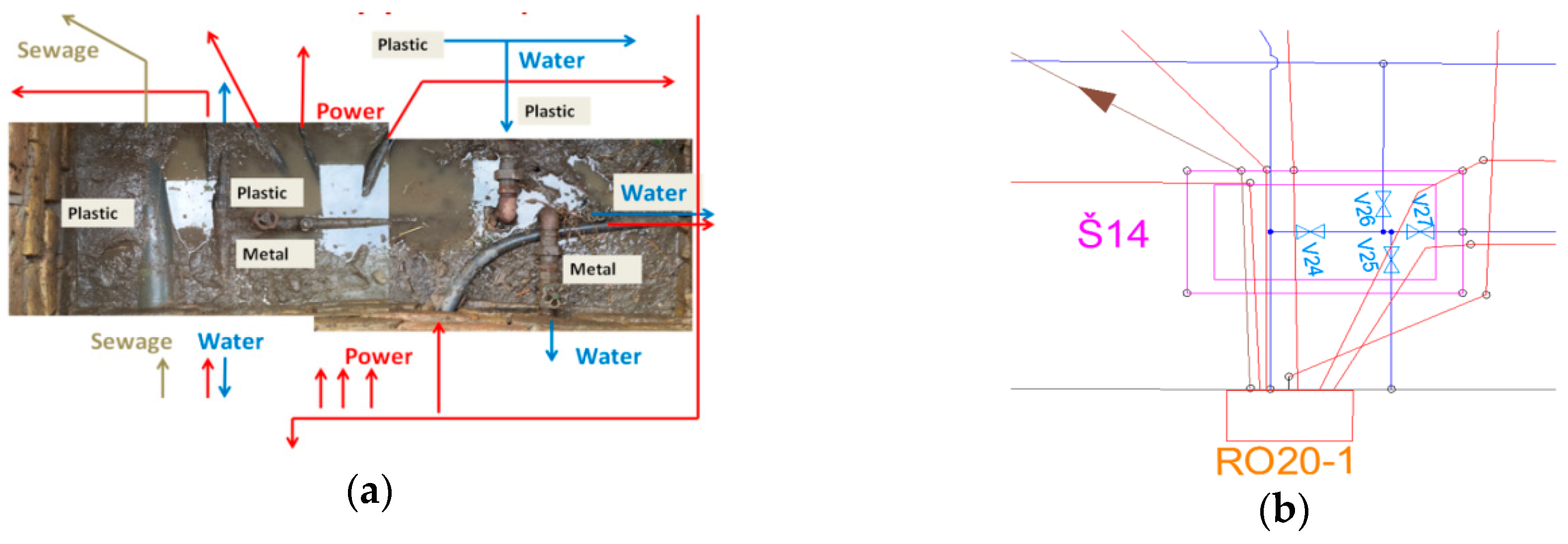
Data in the utility network cadastre are 2D based. Formats used to store the geometric data of the utility lines are dxf and shapefiles (shp). Geometric data are mostly created in a CAD environment and then exported in shp files, which means that often one geometry in a shapefile is not the whole utility line. Another issue is related to situations where the 2D view does not provide good insight into the position of the utility lines, such as crossing or passing different types of utility lines at a sharp angle, crossing utility lines from the subterranean to the above ground, and the vertical installation of utility lines in the same trench (due to the lack of space in the zone between the road and the buildings). In older factories, parts of the utility line installations pass under the buildings. In such situations, an overlap of the rights on the building and the utility line is evident. Furthermore, it is often in factory shafts that there are many pipelines and cables that overlap one over the other due to system upgrades and other needs. Figure 1a shows a photo of one shaft in the factory with the indicated type of utility line. Figure 1b shows a 2D map of this shaft in the utility network cadastre. It is very complicated, so in this and other mentioned situations, an overview in 3D could help the user understand the position of the utility lines on the terrain, as well as the extent of the rights and restrictions on the utility lines. There is a certain amount of existing 3D data that are currently not in use in the cadastral system for this purpose.
3. Extended Serbian LADM Country Profile
The data model is the core of the system. In order to resolve some of the problems related to data organization and integration, as well as to achieve efficient access, sharing, and exchange of the utility network data on the principles of interoperability, it is necessary to create a domain model according to the national legislation and current standards in the field of geospatial data. A standardized model of the legal data of utilities and their spatial representation is presented within the ISO 19152: Land Administration Domain Model (LADM). The LADM provides an abstract, conceptual model covering basic information-related components of land administration, including the parties (people and organizations), basic administrative units, rights, responsibilities, restrictions, spatial units (parcels and legal space of buildings and utility networks), spatial sources, and spatial representations of land administration data [4].
One of the reasons for this research was due to the necessity of developing a unified information system of both the real estate and utility network cadastre in Serbia, which is prescribed by Article 157 of the Law. This new cadastral system should be based on a new data model that will support better cadastral (and utility) data management, provide better integrity of the data by establishing relations among the data, and enable a more advanced search of the data.
In order to develop a unified data model, research was performed using the following steps:
- Analysis of the requirements defined in the Law and other relevant rulebooks;
- Analysis of the international standards in the field of the research and the literature review;
- Analysis of the current information systems, the databases, data dictionaries, and code lists;
- Reverse engineering to transform the existing physical model to a logical model;
- Conceptual modeling to capture the concepts of the real estate and utility network cadastres;
- Analysis of whether the conceptual model was conformant to the LADM;
- After proving conformity on Level 2, the Serbian country profile was developed;
- For utilities, connectors, and other related objects and devices, Steps 1–6 were conducted; and
- Since the conformity to the LADM was proven, the extended Serbian country profile was developed.
Steps 1–7 of this research design related to developing the Serbian LADM-based country profile were conducted in the previous paper by the authors [3]. In this paper, research steps 1–6, 8, and 9 were conducted for the existing utility network cadastre information system, national legislation, and scientific literature related to the utilities.
In the last few years, several LADM based country profiles have been proposed, i.e., for Poland [22], the Czech Republic [23], Croatia [24], Malaysia [25], and Korea [26]. In some of these country profiles, the modeling of utilities was considered. In the Czech Republic, the (legal) information of the utility networks is not registered in the cadastre. However, there is an initiative to store the legal data of utilities in the cadastre with the dynamic reference to their geometries located in the database of utility companies. In the Korean country profile, a class for representing utilities was added together with the utility name and adjoining parcel information. In the Malaysian country profile, a class was added to organize the various types of spatial units, and utilities were marked with one level type. In the future, utilities could be more in focus, given that the revision of the ISO 19152 standard envisages a potential broad scope, including utility legal spaces [5].
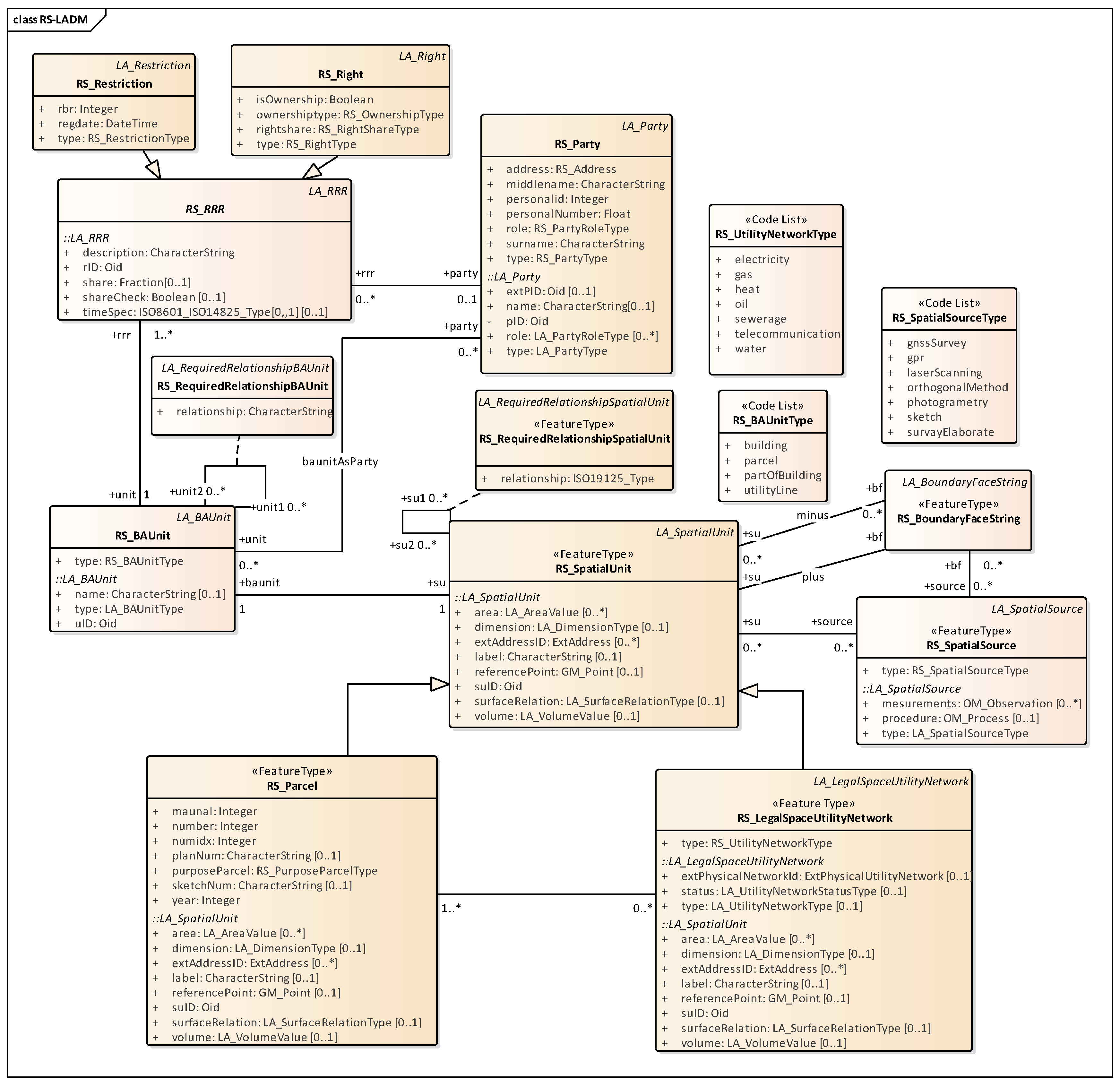
The extracted set of classes from the Serbian LADM profile that were significant for this paper are shown in Figure 2, whereas all classes of the Serbian LADM profile can be found in a previous paper by the authors [3]. All classes from the Serbian country profile have the prefix RS. Core classes of the profile were the RS_SpatialUnit, RS_Party, RS_RRR, and RS_BAUnit. The RS_SpatialUnit class describes spatial objects in the cadastre, including parcels, buildings, and parts of buildings, as well as utility lines and related objects. The class RS_SpatialUnit was further specialized to represent each spatial unit type (e.g., the class RS_Parcel was defined for parcels, etc.).
The country profile allows for the real estate and utility network cadastre data to be joined as required by the Law by introducing the RS_LegalSpaceUtilityNetwork class. The types of utility networks were defined within the RS_UtilityNetworkType code list. Additional associations were added between the RS_Parcel and RS_LegalSpaceUtilityNetwork to record the information about parcels that were above or below the utility line.
The Law describes the legal aspects of utility lines in the same way as it does for the real estate cadastre. This means that the profile classes of RS_Party, which represents the right holders, and RS_RRR, with its subclasses for rights and restrictions (mortgages, easements, and notices), remain the same for the utility line cadastre [3].
Class RS_BAUnit represents a basic administrative unit, which is a set of the rights and restrictions for one real property so that the sum of shares is equal to one. In the Serbian cadastre, the basic administrative unit is equivalent to the real estate folio for parcels, buildings, and part of buildings. Real estate folio types were defined within the RS_BAUnitType code list. Since the data on utility lines are issued in the form of utility line folios, the code list RS_BAUnitType was extended to also contain this value.
A cadastral map for utility lines is a two-dimensional representation of the utility lines. Due to the given constraints, the spatial profile for Serbia was proposed as a 2D topological profile (Figure 2), therefore, the RS_BoundaryFaceString class with a GM_MultiCurve type was used for the geometries.
The class RS_SpatialSource represents any source of 2D or 3D spatial data obtained with one of the methods, such as GNSS survey, photogrammetry, laser scanning, ground penetrating radar, etc.
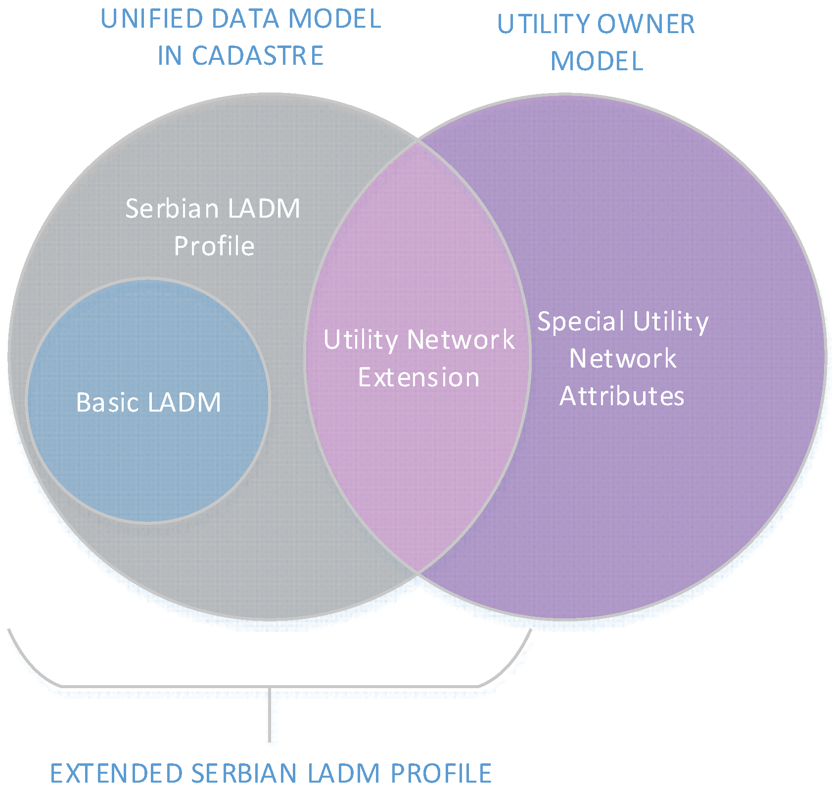
The LADM defined the class LA_LegalSpaceUtilityNetwork as representing the legal space for utility networks. This class can be associated with external classes for physical utility networks via the extPhysicalUtilityNetworkID parameter. This is foreseen for countries where legal utility data are maintained by the cadastre, but physical objects for each separate network are maintained by the owner [16]. However, by analyzing the appropriate legislation, for the case of the Serbian cadastre, it was necessary to extend the LADM profile to include a mandatory set of classes and attributes for the utility lines [27]. The Manual describes in detail the objects of the digital database of the utility network cadastre. Figure 3 shows the Venn diagram of the class and attribute disposition between the cadastre and utility owners and where those attributes should be maintained. A unified data model that should exist in the cadastre consists of the Serbian LADM profile based on basic LADM classes together with the utility network attributes described in the Manual. Together, they represent an extended Serbian LADM profile, as prescribed by the Law. On the utility owner side, there are special utility network attributes that are maintained only by the organizations responsible for the utility lines. These attributes are necessary to monitor the proper functioning of the utility lines and related objects and they should not be part of the unified data model in the cadastre.
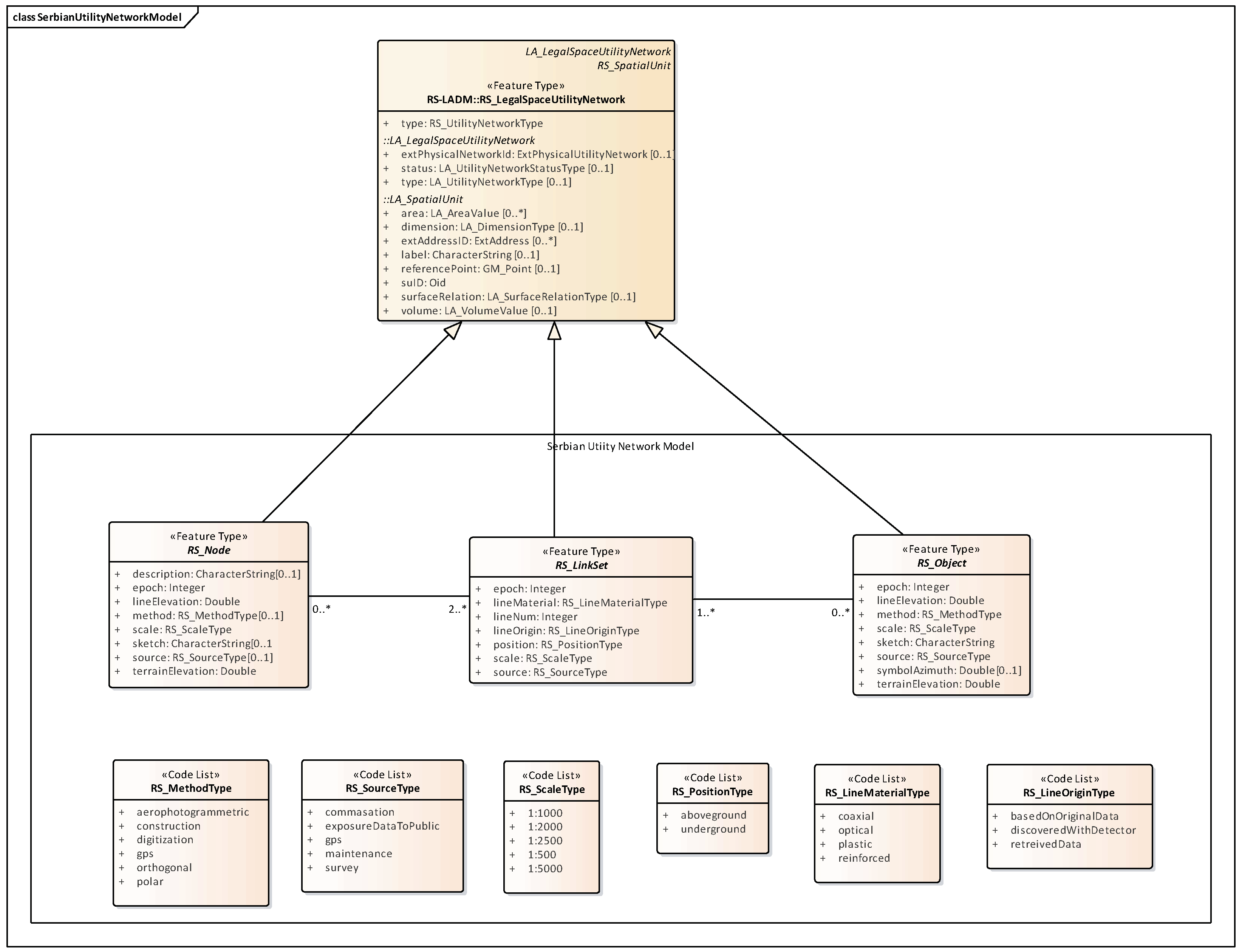
In the Manual, the spatial objects are grouped by the type of geometrical representation—point, polyline, and polygon. All phenomena that do not have a length or surface are represented with points. All phenomena that have a length, but not a surface, are represented with a polyline, and all phenomena that have a surface are represented with polygons. For each type of utility network, a necessary class set is defined. For each phenomenon in one utility network, a type of preferred geometrical representation is specified. This means, for example, that there are two classes for the utility lines for one network type—one for line representation and one for polygon representation. Such data organization is the result of the use of shapefiles that have the ability to store only one type of geometry. However, when looking at any type of utility line network, it can be concluded that its elements can be viewed as a network made up of nodes, link sets, and objects. In order to develop a proper domain model for utility line networks, existing classes defined in the Manual were remodeled. This resulted in a new set of classes that covered the actual concepts of the specific utility line network instead of being based on geometry representation. Utility lines can be seen as link sets, intersection points can be seen as nodes, and related facilities can be seen as objects. Therefore, for the case of a Serbian unified domain model, a Serbian Utility Network Model was defined, as shown in Figure 4. Three abstract classes were defined to represent the network main elements: RS_Node, RS_LinkSet, and RS_Objects, as well as the number of code lists. These classes contain common attributes for the specific network element type.
Class RS_Node represents all connecting points in utility line networks, such as intersections, poles, shafts, etc. A node can be described with terrain elevation and utility line elevation, sketch, method used for data acquisition, scale, etc. Terrain elevation refers to the altitude of the terrain and the utility line elevation relates to the altitude of the utility line connected to the node, which means that it is the altitude of the node itself.
Class RS_LinkSet represents all links and sets of links between nodes, such as utility lines and connectors. One link set represents one utility line, which is described with the position, source type, scale, number of lines, built material, etc.
Class RS_Objects represents facilities that are made along the utility lines and have a significant role in the functioning of the specific utility line network, such as a cable cabin, switchboard, extensions, etc. The object is described by elevation, the method used for data acquisition, scale, source, etc.
Code lists in the Serbian Utility Network Model describe the method for data acquisition, utility line material, origin of the utility data, position of the utility element, and the source of the data.
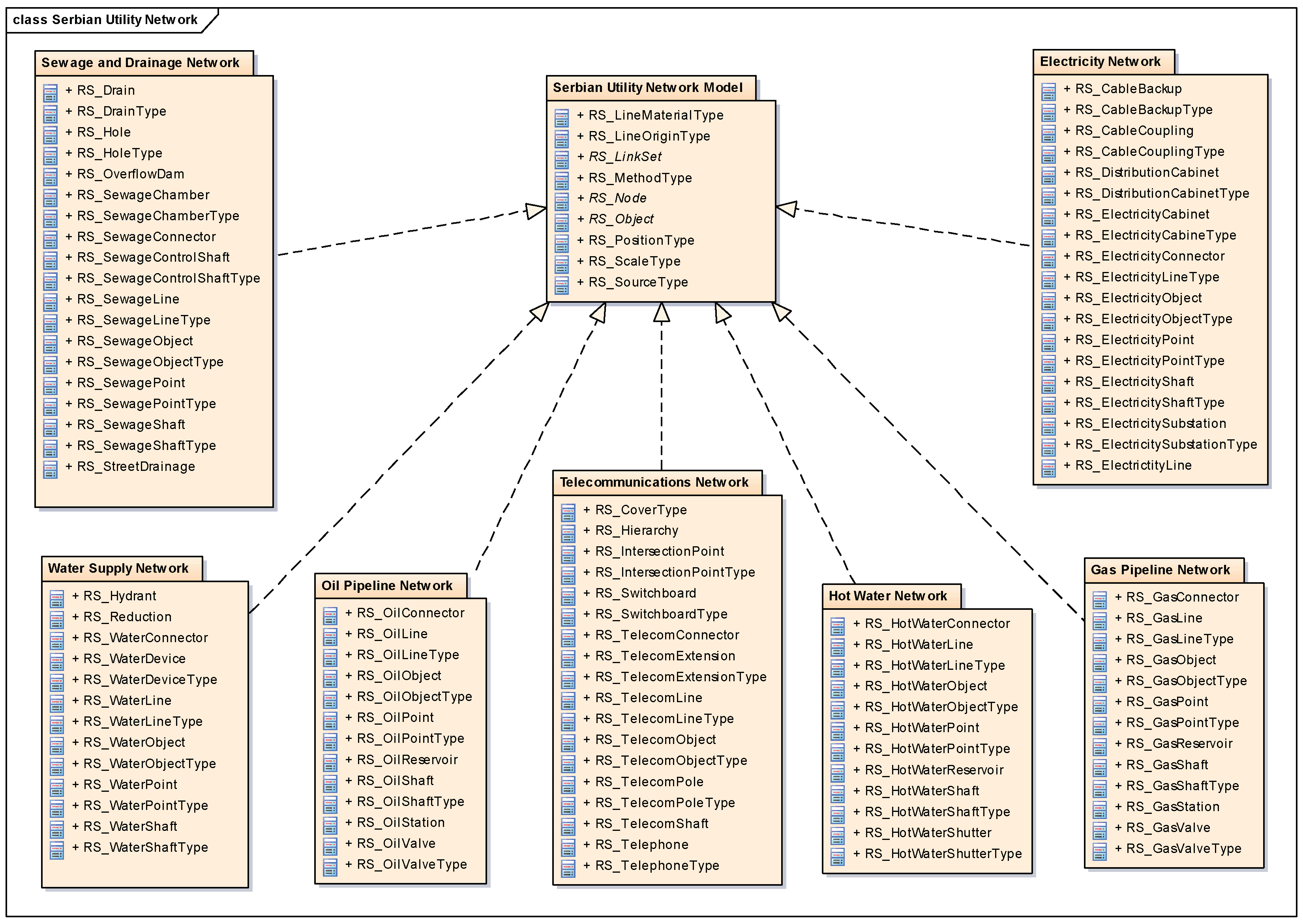
The dependencies between the different utility line network packages are illustrated in Figure 5. All seven types of utility line network (Sewage and Drainage, Water Supply, Oil Pipeline, Telecommunications, Hot Water, Gas Pipeline, and Electricity) packages depend on the Serbian Utility Network Model package, which defines a number of common utility network classes and code lists. The Serbian Utility Network Model is a base model for each type of utility line network model. In order to create a set of classes for each utility line network, it is necessary to specialize the abstract classes RS_Node, RS_LinkSet, and RS_Object.
In the following text, an example of how the classes for a specific utility network were created will be described. For this purpose, a telecommunications network was chosen. For other types of utility line networks, the procedure for the creation of class diagrams remains the same.
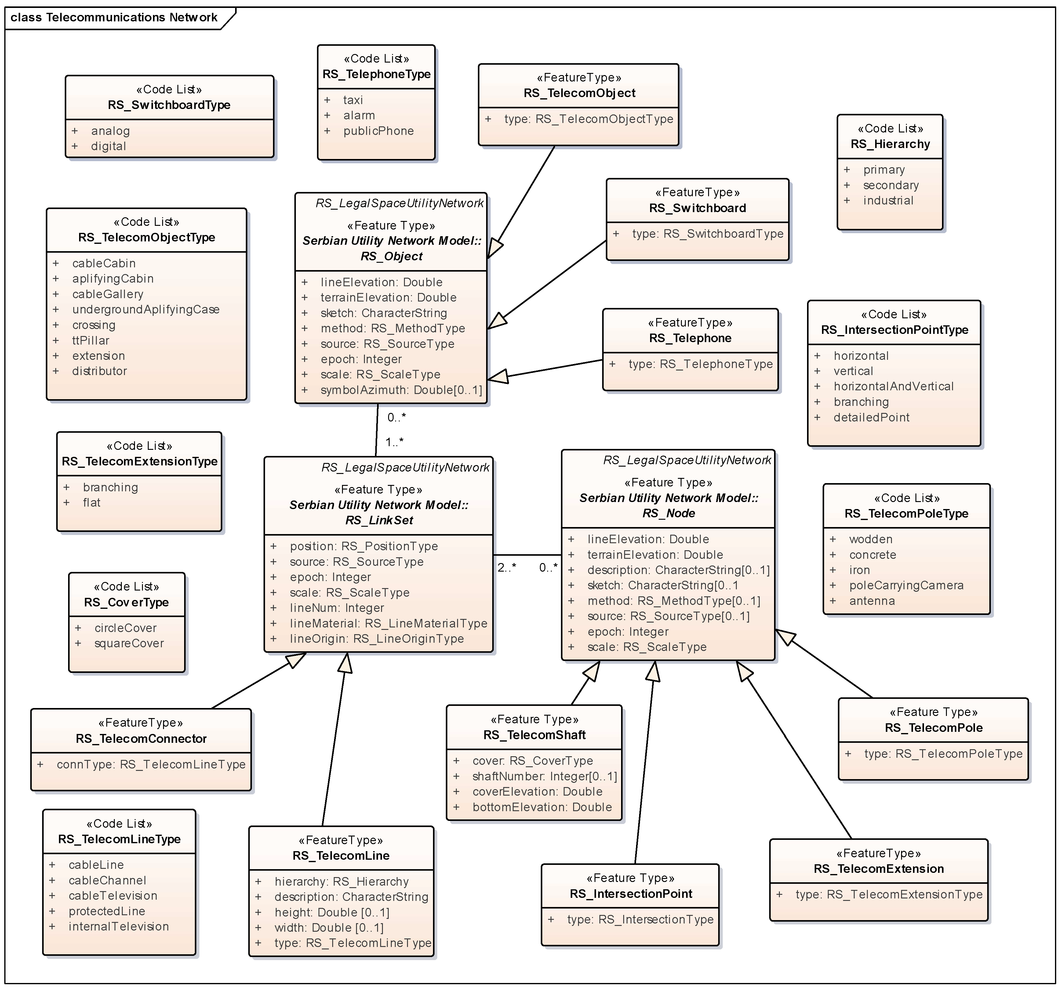
A telecommunications network is a system that allows the exchange of information over significant distances by electronic means and refers to all types of voice, data, and video transmission. Telecommunications include a wide range of information transmitting technologies such as telephones (wired and wireless), microwave communications, fiber optics, satellites, radio and television broadcasting, the Internet, and telegraphs. In order to represent specific elements of the telecommunications network, a class diagram for this type of utility network was modeled (Figure 6). Abstract classes from the Serbian Utility Network Model were specialized in order to cover the necessary telecommunication elements defined in the Manual.
In the case of RS_Node class, the specialized classes are RS_TelecomShaft, RS_IntersectionPoint, RS_TelecomExtension, and RS_TelecomPole. RS_TelecomShaft represents a shaft that can have a circle or square cover, which is described by the shaft number, cover elevation, and bottom elevation. The intersection point of the telecommunication utility lines is described by type, whether it is a horizontal, vertical, branching, or detailed intersection point. Extensions are a part of telecommunications equipment that can be added to a utility line to prolong it. RS_TelecomPole describes the telecommunication poles, which can be made of wood, concrete, iron, etc.
Class RS_LinkSet is specialized by the RS_TelecomLine and RS_TelecomConnector classes. Class RS_TelecomLine represents different types of telecommunication utility lines described by hierarchical level, height and width, and all other attributes derived from RS_LinkSet. Connectors are devices that link the utility line to another part of the telecommunications system installation.
Class RS_Objects is specialized by RS_TelecomObject, RS_Switchboard, and RS_Telephone classes. RS_TelecomObject represent different types of telecommunication objects, such as a cable cabin, amplifying cabin, etc. Class RS_Switchboard refers to an analog or a digital switchboard, while class RS_Telephone refers to different types of telephones in the telecommunications utility line system.
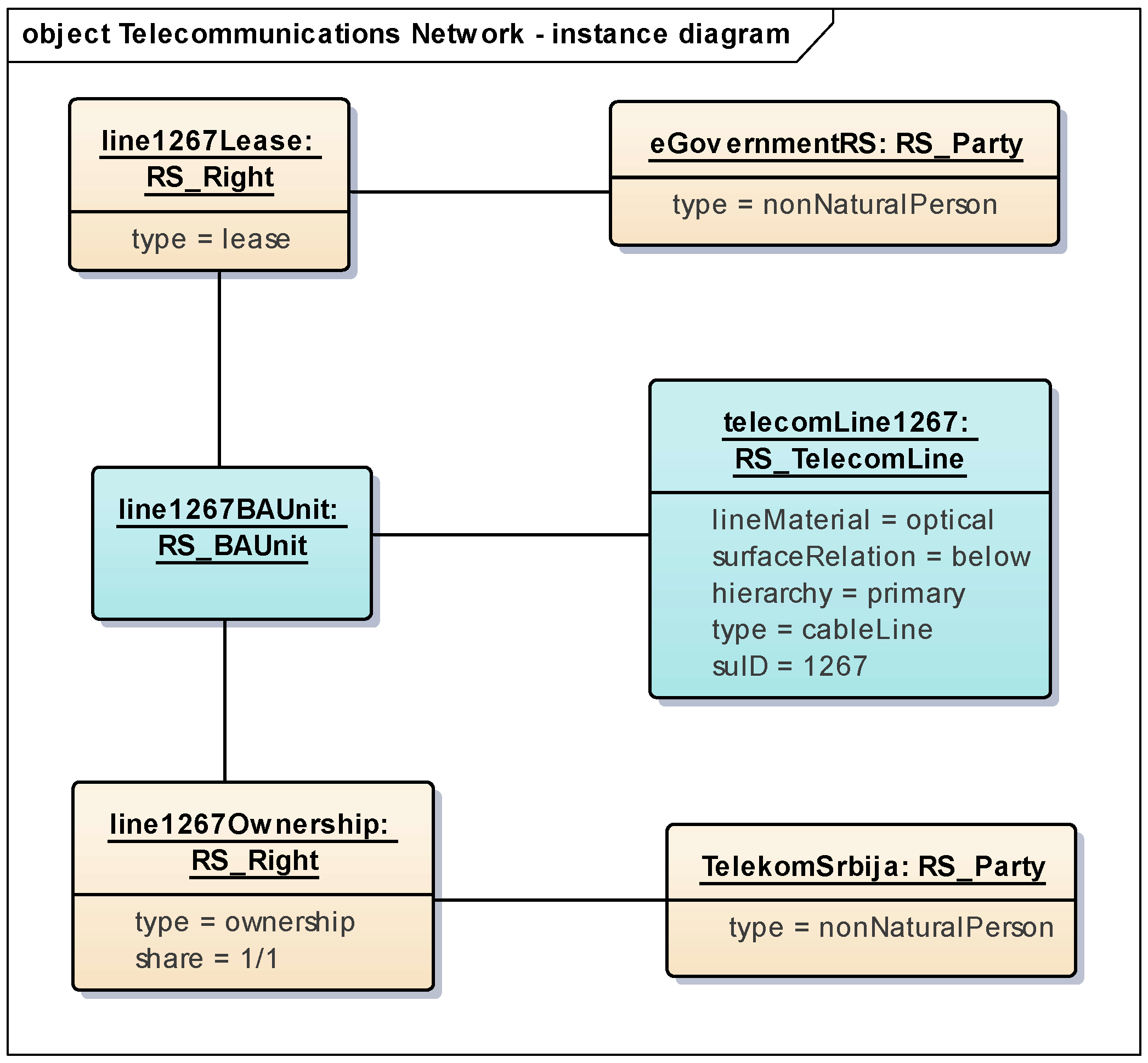
The same procedure was conducted for six other utility network types and resulted in a set of classes within the packages shown in Figure 5. Obtained classes can be used to present the real situation, for example, the registration of ownership and the lease of the optical telecommunication lines. Figure 7 shows the instance diagram of a situation where an optical line is leased for the eGovernment information system.
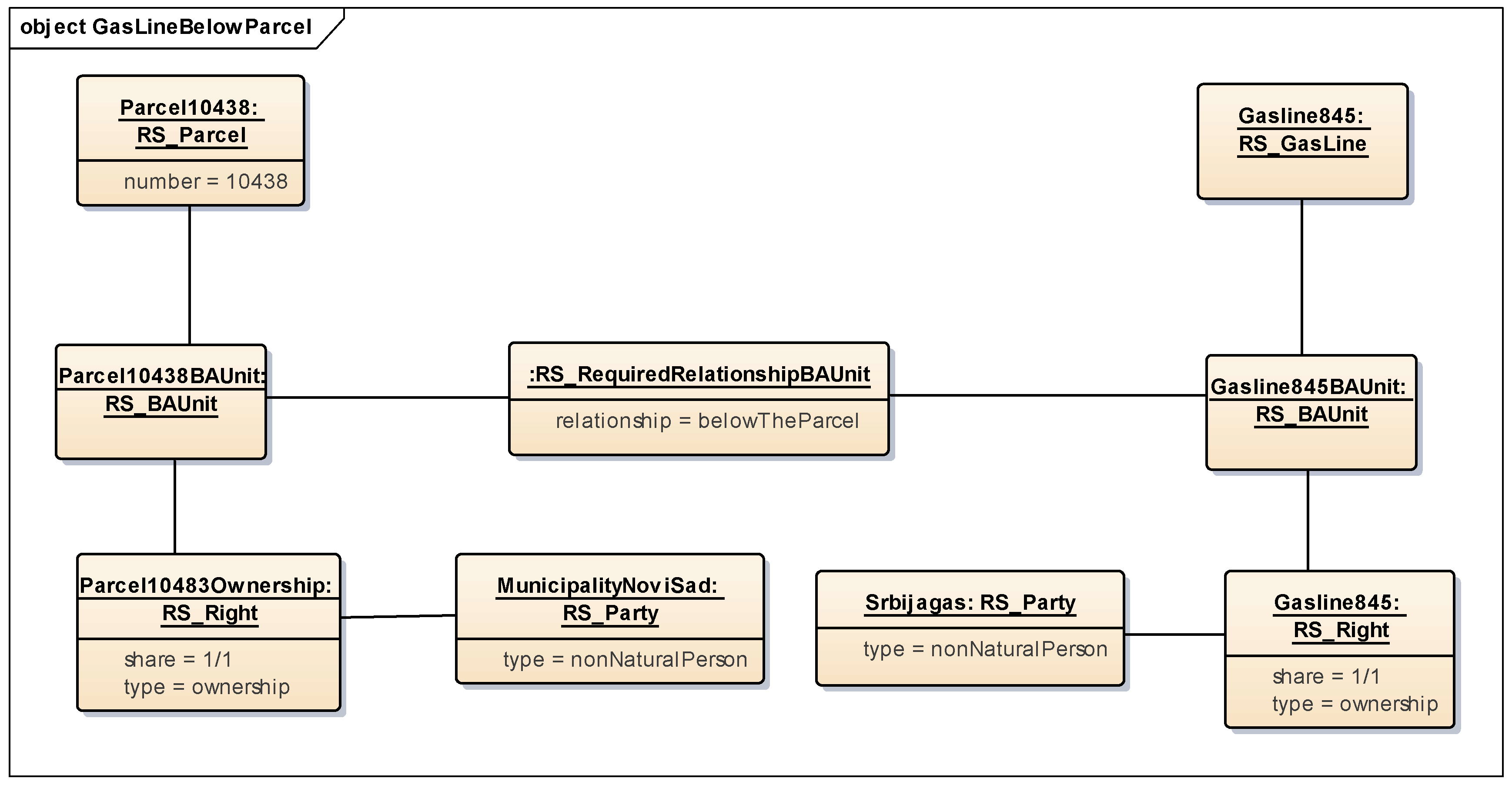
Another example refers to the relationship between gas utility lines and the parcel below where the utility line is located. The Law proposes that from the unified information system, a utility line folio can be issued together with the data on parcels that are below or above the utility line. A connection between the parcel and utility line is achieved with the association between the classes RS_Parcel and RS_LegalSpaceUtilityNetwork. However, since the spatial profile for Serbia is 2D based, an instance of the class RS_RequiredRelationshipSpatialUnit can be created to provide a stronger relationship between the parcel and the utility line. Topological relationships between the parcel and utility line can be verified by implementing the ISO 19125-2 standard and setting the attribute “relationship” of the class RS_RequiredRelationshipSpatialUnit to “ST_Intersects”.
Although the spatial profile for Serbia is currently 2D based, a need to keep the 3D data for specific situations is emphasized in Section 2, particularly since there is a certain amount of existing 3D data. For the case of 3D data in the previous example, the mentioned topological relationship does not stand. In this case, an instance of the class RS_RequiredRelationshipBAUnit was created to represent the special relationship between the parcel and utility line administrative units. Figure 8 shows an example of the instance diagram for a gas utility line that is located below the parcel. A similar instance diagram can be developed for the situation where a gas utility line is located above the parcel. For this case, the attribute “relationship” should be changed to “aboveTheParcel”.
4. Discussion
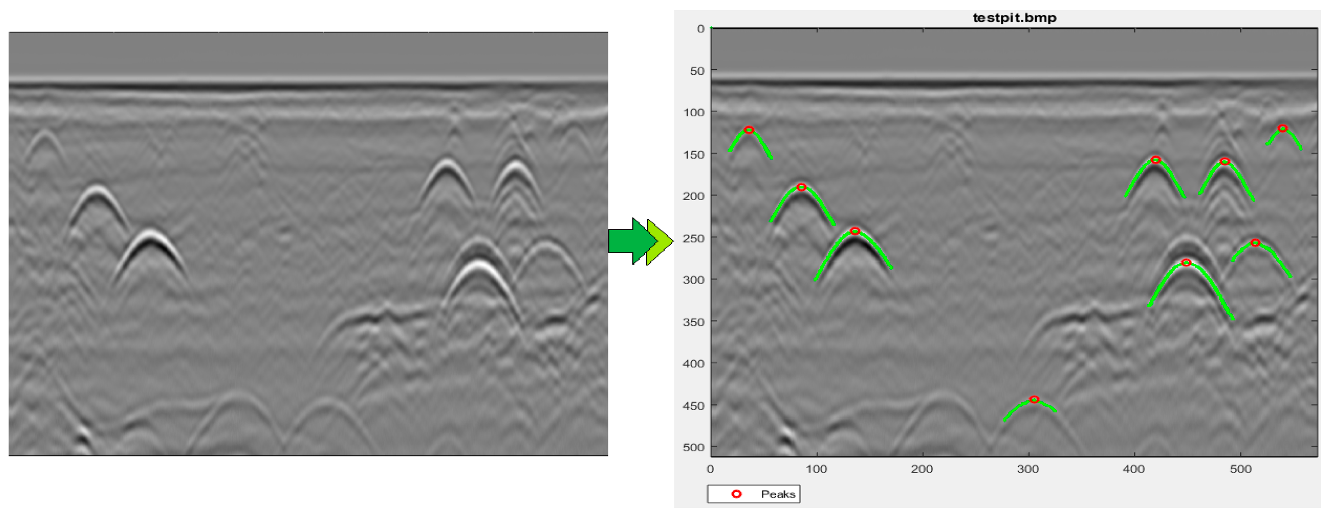
Existing problems regarding maintenance and visualization in the utility network cadastre have already been mentioned in Section 2. In practice, when the right holders make changes to utility lines, it is necessary to record the data about that change in the utility network cadastre. In many situations, this is not done, and the actual state does not correspond to the one in the utility network cadastre. In these situations, it is necessary to find a way to obtain the correct data without digging in the field, in the case of underground utilities. As a solution for underground utilities, a ground penetrating radar (GPR) combined with an electromagnetic locator can be used [18]. When the GPR device moves above the surface, the transmitting antenna sends polarized, high frequency electromagnetic (EM) waves into the ground. Some of the EM waves are reflected from the dielectric boundary and the rest are refracted and go toward the deeper layers. This process is repeated until the EM waves become too weak. Based on this information, the GPR calculates the relative depth of the underground utility. Raw data acquired by the GPR device are processed in several steps (Figure 9).
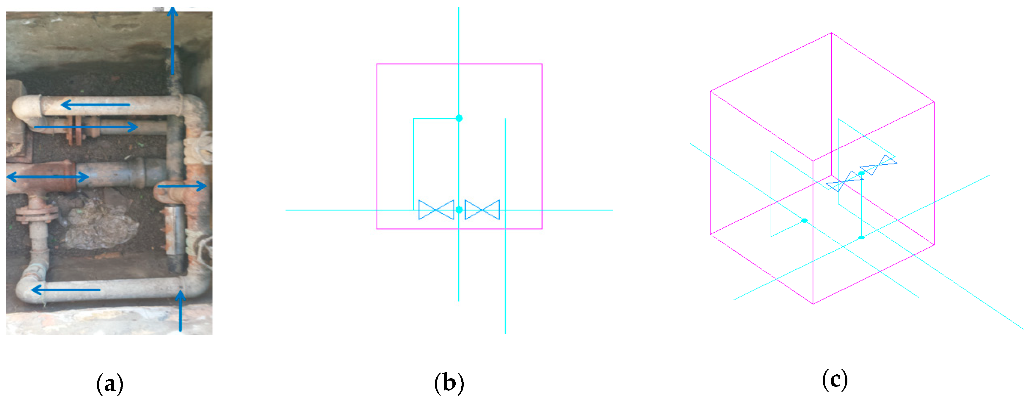
Based on georeferenced radargrams, photography, and relative measurements, this technology allows the user to transform on-site results into 2D or 3D models of underground utilities [28,29]. This is particularly important, since in the underground utility network, there are many examples of overlapping rights in 3D. Figure 10a shows a photograph of the water pipes in a factory shaft. There are many inputs and outputs from the shaft, branching where the pipes change direction to higher or lower levels. The arrows indicate the flow direction of the fluid through the pipelines. Figure 10b shows a classic 2D view of the shaft where it is completely unclear how the pipelines in the shaft are organized. Figure 10c represents the 3D view of the shaft and gives a clear picture of the position of the pipelines and devices in the shaft. The 3D model format is dxf, and 2D data can be converted to shp. Since the Serbian utility network cadastre is 2D based, the obtained 3D data for this situation are not recorded in the cadastre.
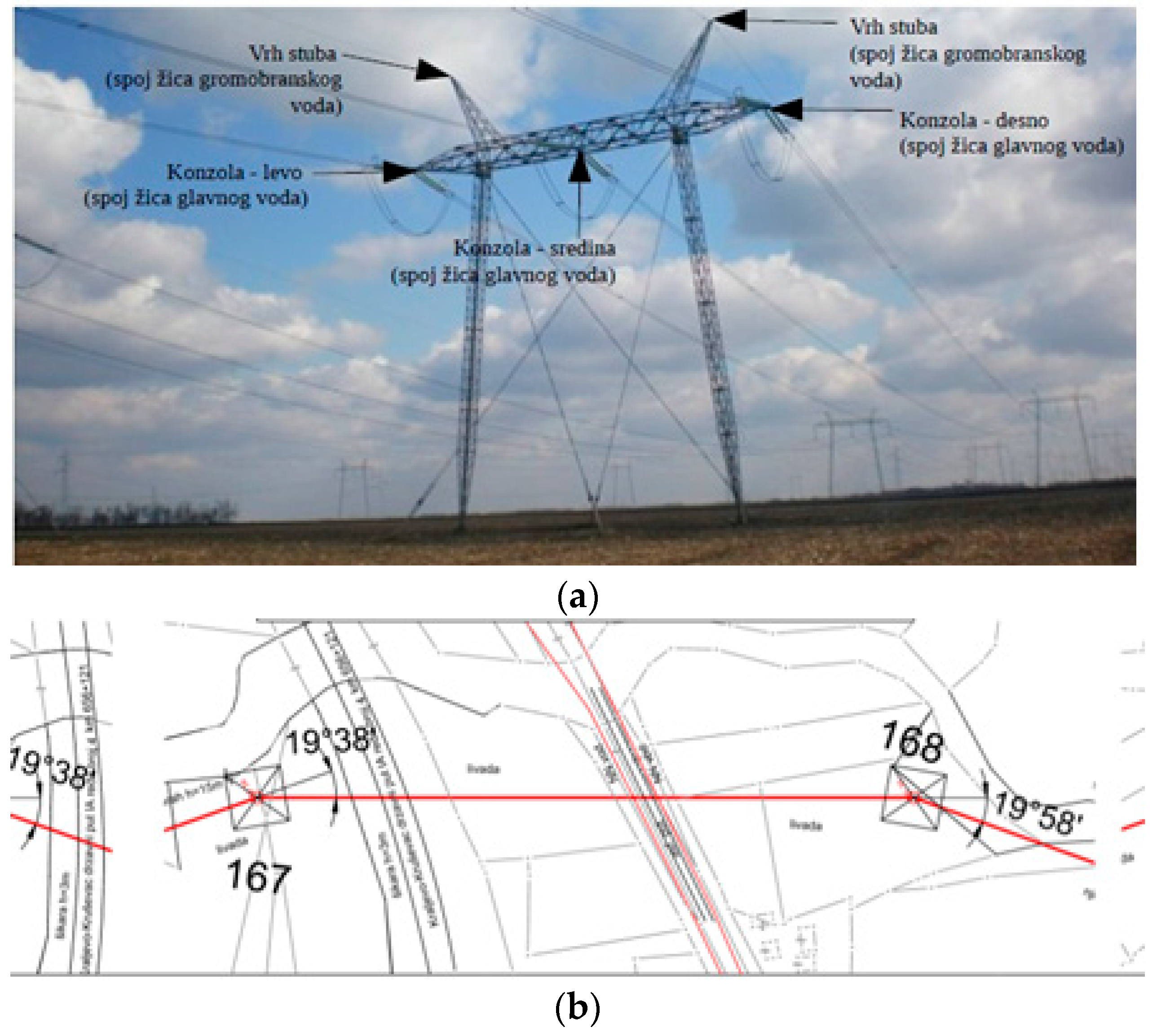
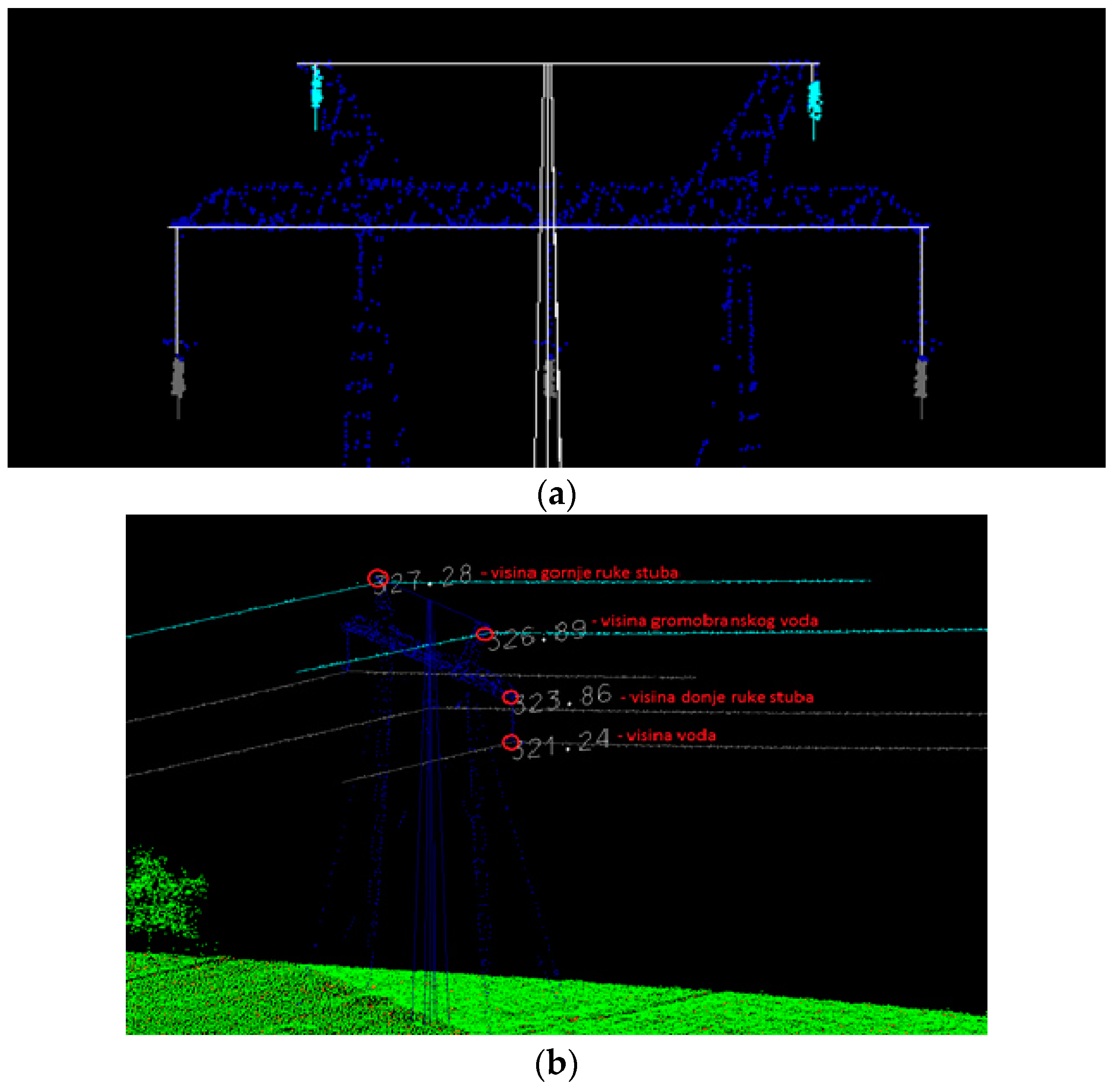
In the case of utility lines located above the surface, such as powerlines, LIDAR technology can be used for 3D data acquisition. Several projects concerning the LIDAR surveying of powerlines for the purpose of legalization have been undertaken [19]. For the area of interest, a LIDAR point cloud and an orthophoto were used as a starting point in producing the valuable data for the utility network cadastre. The processing of data implies the classification of the point cloud automatically and manually, as well as the 3D and 2D vectorization of the poles and powerlines. The final result is a 3D vector in the dgn format. Since the utility network cadastre in Serbia only supports 2D spatial data, 2D data was derived from it and used as an input for the utility network cadastre. The conversion procedure from 3D to 2D implied making a longitudinal profile along a tangent field with corresponding descriptions, stations, angles, cultures, types of roads, rivers, channels, and all objects located in the observed area. The procedure itself is not automated, but the selection of appropriate tools can result in a projection of all of the desired or selected objects from the 3D into the 2D space. The output format is 3D dgn and 2D dwg. Figure 11a shows a photo of a pole with powerlines, while Figure 11b shows a 2D representation of the powerlines. Figure 12 shows 3D representations of a pole (Figure 12a) and powerlines (Figure 12b).
In order to prevent the loss of available information, such 3D data can be referenced as a spatial source (RS_SpatialSource). The 2018 Law introduced the new concept of each property being identified with a unique property identification number (UPIN). This is particularly important to mark real estate in 3D data sources and facilitates the search for a desired utility line in a 3D data source. However, in this case, users would still not be able to have a one-to-one association between the 3D geometry and attribute data of the utility objects. This brings up the question of whether some of the existing utility network data models could be used for the purpose of a more efficient visualization of the desired 3D data.
Several utility network data models for visualization, exchange, analysis, and storage of utility network data have been developed by different organizations to meet the needs of a specific domain [30,31,32]. In the literature, the most commonly mentioned utility network data models are the INSPIRE Utility Networks model [33], IFC (Industry Foundation Classes) Utility model [34], ESRI Utility Network model [35], LandInfra [36], PipelineML [37], and the CityGML Utility Network ADE (Application Domain Extension) [38]. Most of these focus on 2D representation, with the exception of the CityGML Utility Network ADE and the IFC Utility model. These two models include 3D geometric information of the utility lines [10].
The IFC Utility model provides 2D and 3D representation of utilities and has a rich semantic categorization of utility network objects. However, this standard was developed to model utilities at the building level and embedding data into the urban city scale is not supported. Furthermore, the IFC Utility model lacks geospatial information.
On the other hand, the CityGML Utility Network ADE, as the one of about 44 existing CityGML ADEs [39], embeds the utility networks into a 3D city urban space. This ADE allows dual representation of both the network topography and topology as well as the representation of the topographic and functional aspects of the utility networks. Additionally, the CityGML Utility Network ADE considers interdependencies between the utility network features and city objects, as well as interdependencies between the network features of different network types [31]. Ideas for mapping interior utilities from the BIM (Building Information Modeling) to CityGML Utility Network ADE were described by Hijazi et al. [40].
Based on a previous analysis, the use of the CityGML Utility Network ADE seems to better fit the needs of the Serbian data. This ADE contains a network model similar to the Serbian Utility Network Model proposed in Section 3. In addition, this model covers not only the physical representation of the utilities, but also has some attribute values that describe utilities in more detail, such as in the extended Serbian country profile. Utility data in this format could be obtained by combining the 2D and 3D geometries (shp and dxf or dgn) with some of the attribute data from the extended Serbian LADM profile by means of a feature manipulation engine (FME). The idea for this is based on the possibility that existing 3D and 2D data can be converted into CityGML Utility Network ADE data and stored in a database. Since the legal space for utilities corresponds to a physical representation of the utilities, in this situation, a one-to-one link between the attribute data (legal or descriptive) and geometries can be established in the database via the UPIN, and the data can be efficiently visualized. Serbian 2D data contain information about the altitude, so with this solution, they can be converted and would result in the 3D data. Furthermore, the CityGML Utility Network ADE data could be integrated with existing CityGML objects in order to obtain a complete insight of the 3D city urban area. This solution will be analyzed further in future work.
5. Conclusions
The paper provides an overview on how the utility network cadastre in Serbia is organized based on the Law on State Survey and Cadastre that regulates all geodetic practice in Serbia. It also emphasizes the issues that arise during the implementation of the Law and the necessity of introducing a unified data model of the real estate cadastre and utility network cadastre through the development of the extended Serbian LADM country profile. The obtained profile would enable full implementation of the Law and faster and more efficient functioning of the unified information system. The proposed solution is an academic study based on the review of standards and scientific literature with the aim of being implementable and usable in practice. Since the announced future revision of LADM also considers a possible focus on utility networks, the contribution of this paper to the scientific community is also to provide an interesting case study of the Serbian utility network cadastre, where utilities are considered as separate legal objects that can be sold or leased.
Although 3D technologies for the acquisition of utility data is relatively new, their use is increasing. Considering the fact that the current workflows are based on deriving 2D data from 3D data, we analyzed the possibilities of using the 3D utility data. The paper describes examples of using 3D data for utility networks and presents a means to facilitate this data through links with 3D spatial sources. However, the drawback of this solution is that the 3D data cannot be queried together with the 2D data within one (spatial database) environment. In order to overcome this problem, the possibility of identifying 3D spatial units by using existing utility network models, such as the CityGML Utility Network ADE, was also analyzed and will be examined in detail in future work. This will be aligned with the future possible update of the LADM standard and technological developments. When the final solution is reached, the next step will be to propose its implementation and standardization at a national level through the means of the development of rule books for the procedures of the acquisition of data, maintenance, and quality assurance, and possible amendments to the Law in the years to come.
Author Contributions
Conceptualization, Aleksandra Radulović; formal analysis, Aleksandra Radulović; investigation, Aleksandra Radulović, Aleksandar Ristić, and Dušan Jovanović; methodology, Aleksandra Radulović; supervision, Dubravka Sladić and Miro Govedarica; writing—original draft, Aleksandra Radulović, Aleksandar Ristić, and Dušan Jovanović; writing—review and editing, Dubravka Sladić.
Funding
This research received no external funding.
Acknowledgments
Results presented in this paper are part of the research conducted within Grant No. 37017 through the Ministry of Education and Science of the Republic of Serbia.
Conflicts of Interest
The authors declare no conflict of interest.
References
- Official Gazette of the Republic of Serbia. The Law on State Survey and Cadastre. 2009. Available online: http://paragraf.rs/propisi/zakon_o_drzavnom_premeru_i_katastru.html (accessed on 6 March 2019).
- Republic Geodetic Authority of Republic of Serbia. The Manual for Implementation and Maintenance of the Utility Network Digital Database. 2005. Available online: http://www.rgz.gov.rs/dokumenta/stru%C4%8Dna-uputstva (accessed on 6 March 2019).
- Radulović, A.; Sladić, D.; Govedarica, M. Towards 3D Cadastre in Serbia: Development of Serbian Cadastral Domain Model. ISPRS Int. J. Geo-Inf. 2017, 6, 312. [Google Scholar] [CrossRef]
- ISO 19152:2012 Geographic information—Land Administration Domain Model (LADM). Available online: https://www.iso.org/standard/51206.html (accessed on 6 March 2019).
- Van Oosterom, P.; Lemmen, C.; Thompson, R.; Janečka, K.; Zlatanova, S.; Kalantari, M. 3D Cadastral Information Modelling. In Best Practices 3D Cadastres, Extended version; Van Oosterom, P., Ed.; International Federation of Surveyors (FIG): Copenhagen, Denmark, 2018; pp. 95–131. ISBN 978-87-92853-64-6. [Google Scholar]
- Janečka, K.; Bobíková, D. Registering the underground objects in the 3D cadastre: a case study of wine cellar located in the vineyard area Tokaj. Acta Montan. Slovaca 2018, 23, 260–270. [Google Scholar]
- Kim, S.; Kim, J.; Jung, J.; Heo, J.; Zlatanova, S.; Khoshelham, K. Development of a 3D Underground Cadastral System with Indoor Mapping for As-Built BIM: The Case Study of Gangnam Subway Station in Korea. Sensors 2015, 15, 30870–30893. [Google Scholar] [CrossRef] [PubMed] [Green Version]
- Stoter, J.; Ploeger, H.; Roes, R.; Van Der Riet, E.; Biljecki, F.; LeDoux, H.; Kok, D.; Kim, S. Registration of Multi-Level Property Rights in 3D in The Netherlands: Two Cases and Next Steps in Further Implementation. ISPRS Int. J. Geo-Information 2017, 6, 158. [Google Scholar] [CrossRef]
- Pouliot, J.; Girarde, P. 3D Cadastre: With or Without Subsurface Utility Network? In Proceedings of the 5th International FIG Workshop on 3D Cadastres, Athens, Greece, 18–20 October 2016. [Google Scholar]
- Yan, J.; Jaw, S.W.; Van Son, R.; Soon, K.H.; Schrotter, G. Three-dimensional data modelling for underground utility network mapping. In Proceedings of the ISPRS TC IV Mid-term Symposium “3D Spatial Information Science – The Engine of Change”, Delft, The Netherlands, 1–5 October 2018. [Google Scholar]
- Cevdet, C.A. Usage of Underground Space for 3D Cadastre Purposes and Related Problems in Turkey. Sensors 2008, 8, 11. [Google Scholar]
- Ghawana, T.; Hespanha, J.; Khandelwal, P.; van Oosterom, P. 3D Cadastral Complexities in Dense Urban Areas of Developing countries: Case Studies from Delhi and Satellite Towns. In Proceedings of the FIG Working Week 2013, Abuja, Nigeria, 6–10 May 2013. [Google Scholar]
- Spirou-Sioula, K.; Ioannidis, C.; Potsiou, C. Technical Aspects for 3D Hybrid Cadastral Model. Surv. Rev. 2013, 45, 419–427. [Google Scholar] [CrossRef]
- Hashim, M.; Jaw, S.W.; Marghany, M. Subsurface Utility Mapping for Underground Cadastral Infrastructure. In Proceedings of the 31st Asian Conference on Remote Sensing (ACRS), Hanoi, Vietnam, 1–5 November 2010. [Google Scholar]
- Döner, F.; Thompson, R.; Stoter, J.; Lemmen, C.; Ploeger, H.; van Oosterom, P.; Zlatanova, S. Solutions for 4D cadastre – with a case study on utility networks. Int. J. Geogr. Inf. Sci. 2011, 25, 1173–1189. [Google Scholar]
- Döner, F.; Thompson, R.; Stoter, J.; Lemmen, C.; Ploeger, H.; van Oosterom, P.; Zlatanova, S. 4D cadastres: First analysis of legal, organizational, and technical impact—With a case study on utility networks. Land Use Policy 2010, 27, 1068–1081. [Google Scholar]
- Kitsakis, D.; Paasch, J.M.; Paulsson, J.; Navratil, G.; Vučić, N.; Karabin, M.; El-Makawy, M.; Koeva, M.; Janečka, K.; Erba, D.; et al. Legal foundations. In Best Practices 3D Cadastres, Extended version; Van Oosterom, P., Ed.; International Federation of Surveyors (FIG): Copenhagen, Denmark, 2018; pp. 1–66. ISBN 978-87-92853-64-6. [Google Scholar]
- Ristić, A.; Bugarinović, Ž.; Vrtunski, M.; Govedarica, M.; Petrovački, D. Integration of modern remote sensing technologies for faster utility mapping and data extraction. Constr. Build. Mater. 2017, 154, 1183–1198. [Google Scholar] [CrossRef]
- Popović, D.; Pajić, V.; Jovanović, D.; Sabo, F.; Radović, J. Semi-Automatic Classification of Power Lines by Using Airborne Lidar. In Proceedings of the FIG Working Week 2017, Helsinki, Finland, 29 May–2 June 2017. [Google Scholar]
- Official Gazette of the Republic of Serbia. The Rulebook on Cadastre Survey and Real Estate Cadastre. 2016. Available online: http://www.rgz.gov.rs/content/Datoteke/Dokumenta/02%20Pravilnici/Pravilnik%20o%20katastarskom%20premeru%20i%20katastru%20nepokretnosti%2003.02.2016.pdf (accessed on 4 March 2019).
- Official Gazette of the Republic of Serbia. The Law on the Procedure for Registration in the Real Estate Cadastre and Utility Network Cadastre. 2018. Available online: http://www.rgz.gov.rs/content/Datoteke/Dokumenta/01%20Zakoni/%D0%97%D0%B0%D0%BA%D0%BE%D0%BD%20%D0%BE%20%D0%BF%D0%BE%D1%81%D1%82%D1%83%D0%BF%D0%BA%D1%83%20%D1%83%D0%BF%D0%B8%D1%81%D0%B0%20%D1%83%20%D0%BA%D0%B0%D1%82%D0%B0%D1%81%D1%82%D0%B0%D1%80%20%D0%BD%D0%B5%D0%BF%D0%BE%D0%BA%D1%80%D0%B5%D1%82%D0%BD%D0%BE%D1%81%D1%82%D0%B8%20%D0%B8%20%D0%B2%D0%BE%D0%B4%D0%BE%D0%B2%D0%B0_%2041_2018-16(1).pdf (accessed on 4 March 2019).
- Bydłosz, J. The application of the Land Administration Domain Model in building a country profile for the Polish cadastre. Land Use Policy 2015, 49, 598–605. [Google Scholar] [CrossRef]
- Janečka, K.; Souček, P. A Country Profile of the Czech Republic Based on an LADM for the Development of a 3D Cadastre. ISPRS Int. J. Geo-Inf. 2017, 6, 143. [Google Scholar] [CrossRef]
- Vučić, N.; Markovinović, D.; Mičević, B. LADM in the Republic of Croatia-making and testing country profile. In Proceedings of the 5th FIG International Land Administration Domain Model Workshop 2013, Kuala Lumpur, Malaysia, 24–25 September 2013. [Google Scholar]
- Zulkifli, N.A.; Rahman, A.A.; Van Oosterom, P.; Choon, T.L.; Jamil, H.; Hua, T.C.; Seng, L.K.; Lim, C.K. The importance of Malaysian Land Administration Domain Model country profile in land policy. Land Use Policy 2015, 49, 649–659. [Google Scholar] [CrossRef]
- Lee, B.M.; Kim, T.J.; Kwak, B.Y.; Lee, Y.; Choi, J. Improvement of the Korean LADM country profile to build 3D cadastre model. Land Use Policy 2015, 49, 660–667. [Google Scholar] [CrossRef]
- Radulović, A.; Sladić, D.; Govedarica, M.; Ristić, A.; Jovanović, D. Towards 3D Utility Network Cadastre: Extended Serbian LADM Country Profile. In Proceedings of the 6th International FIG Workshop on 3D Cadastres, Delft, The Netherlands, 2–4 October 2018. [Google Scholar]
- Bugarinović, Ž.; Meschino, S.; Vrtunski, M.; Pajewski, L.; Ristić, A.; Derobert, X.; Govedarica, M. Automated Data Extraction from Synthetic and Real Radargrams of Complex Structures. J. Environ. Eng. Geophys. 2018, 23, 407–421. [Google Scholar]
- Ristić, A.; Bugarinović, Ž.; Vrtunski, M.; Govedarica, M. Point coordinates extraction from localized hyperbolic reflections in GPR data. J. Appl. Geophys. 2017, 144, 1–17. [Google Scholar] [CrossRef]
- Hijazi, I.; Kutzner, T.; Kolbe, T.H. Use Cases and their Requirements on the Semantic Modeling of 3D Supply and Disposal Networks. In Proceedings of the 37. Wissenschaftlich-Technische Jahrestagung der DGPF, Würzburg, Germany, 8–10 March 2017. [Google Scholar]
- Kutzner, T.; Kolbe, T.H. Extending Semantic 3D City Models by Supply and Disposal Networks for Analysing the Urban Supply Situation. In Proceedings of the Dreiländertagung der DGPF, der OVG und der SGPF, Bern, Switzerland, 7–9 June 2016. [Google Scholar]
- Den Duijn, X.; Agugiaro, G.; Zlatanova, S. Modelling below- and above-ground utility network features with the CityGML Utility Network ADE: experiences from Rotterdam. In Proceedings of the 3rd International Conference on Smart Data and Smart Cities, Delft, The Netherlands, 4–5 October 2018. [Google Scholar]
- INSPIRE Thematic Working Group Utility and Governmental Services. Data Specification on Utility and Government Services—Technical Guidelines. 2013. Available online: http://inspire.ec.europa.eu/documents/Data_Specifications/INSPIRE_DataSpecification_US_v3.0.pdf (accessed on 7 March 2019).
- ISO 16739-1:2018 Industry Foundation Classes (IFC) for Data Sharing in the Construction and Facility Management Industries—Part 1: Data Schema. Available online: https://www.iso.org/standard/70303.html (accessed on 7 March 2019).
- ESRI. The Road Ahead for Network Management. 2016. Available online: http://proceedings.esri.com/library/userconf/public-sector-wpb17/papers/public-sector_52.pdf (accessed on 7 March 2019).
- OGC Land and Infrastructure Conceptual Model Standard (LandInfra). Available online: http://docs.opengeospatial.org/is/15-111r1/15-111r1.html (accessed on 7 March 2019).
- OGC Candidate Standard—PipelineML. Available online: http://www.pipelineml.org (accessed on 7 March 2019).
- Kutzner, T.; Kolbe, T.H. CityGML Utility Network ADE—Scope, Concepts, and Applications. In Proceedings of the Underground Infrastructure Mapping and Modeling Workshop, New York, NY, USA, 24–25 April 2017. [Google Scholar]
- Biljecki, F.; Kumar, K.; Nagel, C. CityGML Application Domain Extension (ADE): overview of developments. Open Geospatial Data Softw. Stand. 2018, 3, 13. [Google Scholar] [CrossRef]
- Hijazi, I.; Ehlers, M.; Zlatanova, S.; Becker, T.; van Berlo, L. Initial Investigations for Modeling Interior Utilities Within 3D Geo Context: Transforming IFC-Interior Utility to CityGML/UtilityNetworkADE. In Advances in 3D Geo-Information Sciences; Kolbe, T., König, G., Nagel, C., Eds.; Springer: Berlin/Heidelberg, Germany, 2010; pp. 95–113. ISBN 978-3-642-12670-3. [Google Scholar] [Green Version]
Figure 1.
(a) A photo of a shaft in a factory; (b) a 2D map of the shaft in the utility network cadastre.
Figure 1.
(a) A photo of a shaft in a factory; (b) a 2D map of the shaft in the utility network cadastre.

Figure 2.
Extracted set of classes from the Serbian LADM profile.

Figure 3.
Venn diagram of the class and attribute disposition between models.

Figure 4.
The Serbian Utility Network Model.

Figure 5.
Overview of the utility line networks with the UML (Unified Modeling Language) structure and dependencies.
Figure 5.
Overview of the utility line networks with the UML (Unified Modeling Language) structure and dependencies.

Figure 6.
Specialization of the Serbian Utility Network Model for the telecommunications network.

Figure 7.
Instance diagram showing the lease on optical cable lines.

Figure 8.
Instance diagram of a gas line located below the parcel.

Figure 9.
Raw and processed radargram.

Figure 10.
Water pipes. (a) A photo of a shaft with water pipes; (b) a 2D representation of the water pipes; (c) a 3D representation of the water pipes.
Figure 10.
Water pipes. (a) A photo of a shaft with water pipes; (b) a 2D representation of the water pipes; (c) a 3D representation of the water pipes.

Figure 11.
Powerlines. (a) A photo of a pole with powerlines; (b) a 2D representation of the powerlines.
Figure 11.
Powerlines. (a) A photo of a pole with powerlines; (b) a 2D representation of the powerlines.

Figure 12.
Powerlines. (a) a 3D representation of a pole; (b) a 3D representation of a pole with powerlines.
Figure 12.
Powerlines. (a) a 3D representation of a pole; (b) a 3D representation of a pole with powerlines.

© 2019 by the authors. Licensee MDPI, Basel, Switzerland. This article is an open access article distributed under the terms and conditions of the Creative Commons Attribution (CC BY) license (http://creativecommons.org/licenses/by/4.0/).
Share and Cite
MDPI and ACS Style
Radulović, A.; Sladić, D.; Govedarica, M.; Ristić, A.; Jovanović, D. LADM Based Utility Network Cadastre in Serbia. ISPRS Int. J. Geo-Inf. 2019, 8, 206. https://0-doi-org.brum.beds.ac.uk/10.3390/ijgi8050206
AMA Style
Radulović A, Sladić D, Govedarica M, Ristić A, Jovanović D. LADM Based Utility Network Cadastre in Serbia. ISPRS International Journal of Geo-Information. 2019; 8(5):206. https://0-doi-org.brum.beds.ac.uk/10.3390/ijgi8050206
Chicago/Turabian StyleRadulović, Aleksandra, Dubravka Sladić, Miro Govedarica, Aleksandar Ristić, and Dušan Jovanović. 2019. "LADM Based Utility Network Cadastre in Serbia" ISPRS International Journal of Geo-Information 8, no. 5: 206. https://0-doi-org.brum.beds.ac.uk/10.3390/ijgi8050206
Note that from the first issue of 2016, this journal uses article numbers instead of page numbers. See further details here.