1. Introduction
The BIM concept was introduced in 1970 [
1]. It is a collaborative methodology, used to manage construction projects effectiveness [
2,
3] by architectural, engineering and construction (AEC) industries, based on several BIM-based tools solutions [
4].
Over the years, BIM has become a methodology mainly used to integrate the design of buildings, as it achieves a 3D digital representation of the physical, functional, and semantic characteristics of an environment, structure, or existing building [
5].
There has been a significant push for the development and utilization of innovative technologies in the transportation sector, in which many of the proven technologies and methods from the building industry have been adopted [
6].
BIM can enhance and improve the planning process, design, and construction of projects by offering a novel approach to design, construction, and facility management, in which a digital representation of the infrastructure process is used to facilitate the exchange and interoperability of information in digital format [
7,
8].
BIM platforms are based on components, that is, on stored parametric elements in object libraries. Generally, these stored parametric elements are reusable objects that can contain geometric, semantic, or topological attributes [
9,
10].
BIM technologies allow for the documentation, generation, importation, or manipulation of three-dimensional models using such parametric information as specifications and technical drawings (2D), geometric properties in a collaborative model (3D), constructive temporary programming (four-dimensional (4D)), the definition of amounts and costs (five-dimensional (5D)), sustainability of the project (six-dimensional (6D)), and maintenance and life-cycle management (seven-dimensional (7D)) [
11].
Generally, in BIM, the level of development (LOD) of the project must be represented, so as to determine the degree of certainty, precision, and richness of the information contained in the modeled element and to estimate the specific use for which this information is destined [
12,
13].
Confusion and misunderstanding occur when BIM is seen solely as a 3D model of a facility with added features and functions. In reality, the principle value of BIM is in managing the
information; the 3D modeling is just one way of representing that information, including information about materials, certifications, maintenance procedures, structural, and functional parameters within the models [
14,
15,
16].
Using building information modeling (BIM) in conjunction with emerging technologies for the management of infrastructure can help achieve more reliable, sustainable, and safer performance of the network while decreasing maintenance costs and risks, and at the same time generating considerable revenue for all stakeholders [
17]. Having a comprehensive understanding of this technology, as well as its applications, advantages and disadvantages, advancements and limitations can help owners, designers, and other transportation authorities make more informed decisions in selecting the optimal set of automated and strategic plans for enhanced management of the infrastructure network through its whole life cycle [
18].
To date, designing in a BIM environment increasingly represents the current conditions on site, in that it applies an operational methodology to the construction processing an information model, that is, a model that contains all the information concerning its entire life cycle.
A parallel with a life cycle assessment is therefore evident, in that it is capable of approaching the environmental impact of an element or process, from design to construction, through maintenance to demolition, decommissioning and reuse.
In Italy, in accordance with specific regulations [
19,
20], times and methods have been defined for the progressive introduction of these advanced electronic methods, as required for all new public buildings and large-scale infrastructure projects
In the context of the modeling and development of BIM processes for building engineering and architecture, significant studies and applications have been made and are still ongoing, and considerable problems have arisen in trying to export this solution to the field of civil engineering for infrastructure.
Just as research and regulations have diversified over time—resulting in increased specialization into various fields of engineering and architecture—so to the development of design in the BIM environment today must proceed along parallel paths, gradually interpreting and changing the state of the art in order to develop specialized approaches to the problems of the design process, taking into consideration the needs of the operator who will be either the intermediate or final beneficiary of this process.
A fundamental feature of the BIM methodology is the interactive collaboration between the different professionals who are involved in all phases of the project life cycle, in order to insert, extract, update or modify information in the model. In this iterative process, it is possible to recreate a single virtual model of the design work, which is not a simple three-dimensional geometric representation, but a “dynamic” model, that is, containing a series of additional or complementary information regarding the materials, the elements of the dimensional structure, thermal characteristics and energy performance, costs, safety, maintenance, demolition and decommissioning.
Therefore, owing to the BIM methodology, it is possible to design work as it must be “built” well before its physical realization, through an advanced virtual simulation model, based on an engineering approach, incorporating the collaboration and contributions of all the professionals involved in the project who work on models connected to each other, in a shared and iterative manner [
20].
In this way, BIM and the digital twin model can assist in the design, planning, and maintenance of civil infrastructure as roadways [
21,
22,
23,
24,
25], railways [
26,
27,
28,
29], airports [
30,
31,
32,
33], harbors [
34,
35,
36], bridges [
37,
38,
39] and tunnels [
40,
41,
42,
43,
44].
Despite the extensive literature on the development of BIM and its applications, relatively few research papers—at least to the authors’ knowledge—have been published on the subject information integration in modeling specific infrastructure components, showing critical issues and providing a possible methodology to follows.
2. Aims and Methods
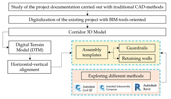
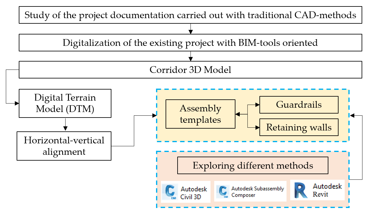
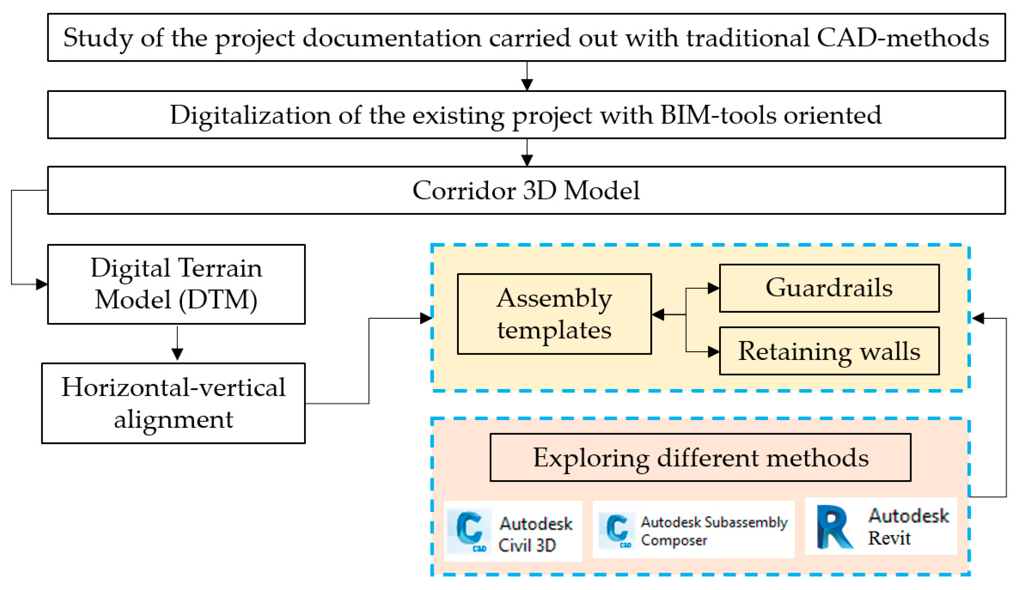
This paper explores some critical issues of the use and application of the BIM process in the infrastructure field, in particular in modeling specific elements such as guardrails and retaining walls not yet well structured and editable in the default library of BIM-based tools.
As shown in
Figure 1, an alternative methodology is presented for better implementation of these elements in the main 3D model evaluating the actual iteration between the BIM-based tools of the same software-house, in particular Autodesk
® Civil 3D, Subassembly Composer and Revit.
3. Case Study
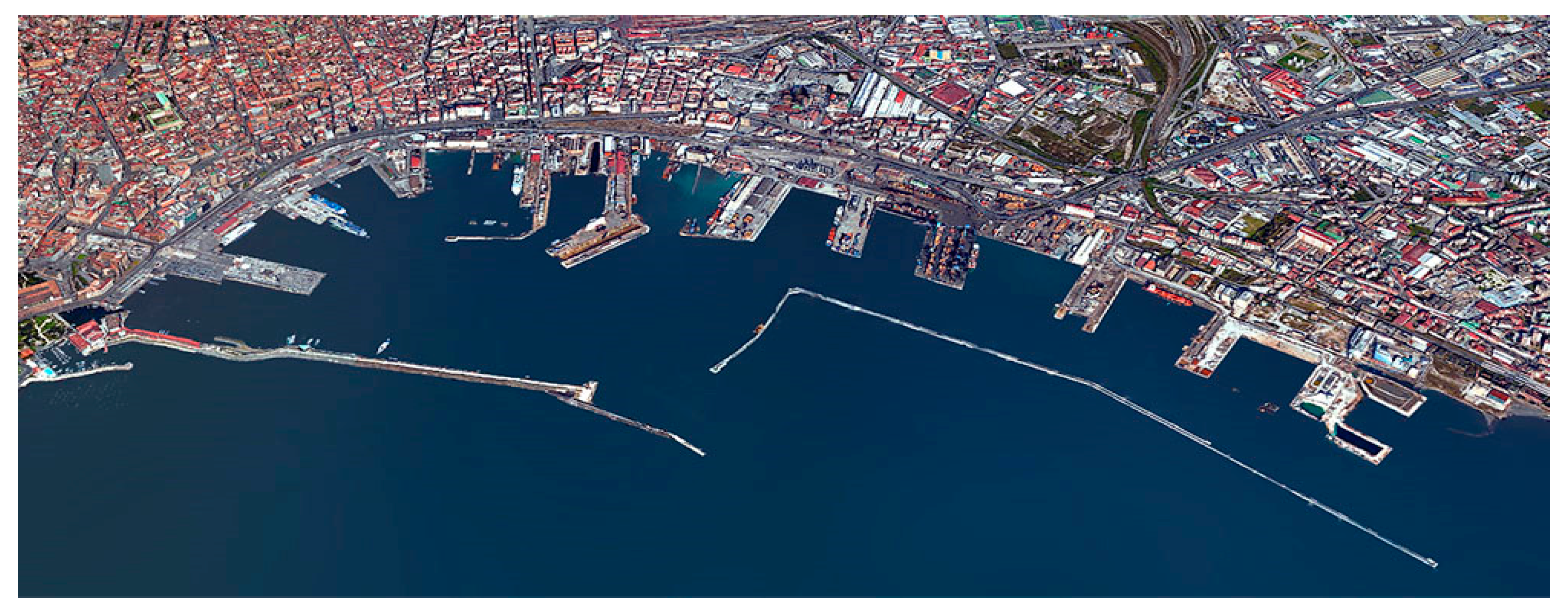
A gradual process of upgrading Italy’s infrastructure has begun through the creation of new connection systems and commercial hubs. Among the main works of interest is the adaptation and strengthening of rail and road connections in Naples Harbor shown in
Figure 2, identified as the primary Port Hub in the central Mediterranean.
With the interventions, a general reorganization of the functions within the port is contemplated, with a rationalization of the terminals and the creation of new landings, diversifying the typology of internal flows and creating a new large container terminal of the Levante dock, capable of receiving the latest container ships and handling no less than 800 thousand TEU/year over an area of approximately 100 ha.
The initialization of these study processes, together with the advanced level of design involved in the new terminal of the Darsena di Levante, requires that the project for the adaptation of the port infrastructure system considers the following aspects:
The absence of an adequate internal road connection between the western and eastern sectors;
The lack of connections from the new eastern terminal to the motorway networks;
The inadequacy of the existing road networks, present in the territory of the municipality of Naples, to be converted by minimizing the impact on the urban transport system;
The shortcomings of the railway connection between the west and east sectors of the port and/or an adequate connection between the east sector and the external line;
The absence of a suitable railway yard proportionate to the volume of project traffic.
On the basis of the project solutions proposed by the Preliminary Project (October 2009) a Definitive Project (year 2012) has been drawn up, relating to the interventions concerning both road and rail connections, aiming to solve the most immediate critical issues and to create a connection between the western harbor area and the harbor area of binder and to pursue railway traffic objectives in the order of 150–200 TEU, then estimated at 2020.
The current project for the reorganization of road and rail connections has its own bases in an intensive and accurate study activity, the groundwork for which involves the need to draw up an Executive Project aimed at the realization of the aforementioned works.
The conducted analysis has highlighted the existence of its own aspects which are not optimal if they refer to the actual destination of use of the road infrastructure in the new port reorganization framework.
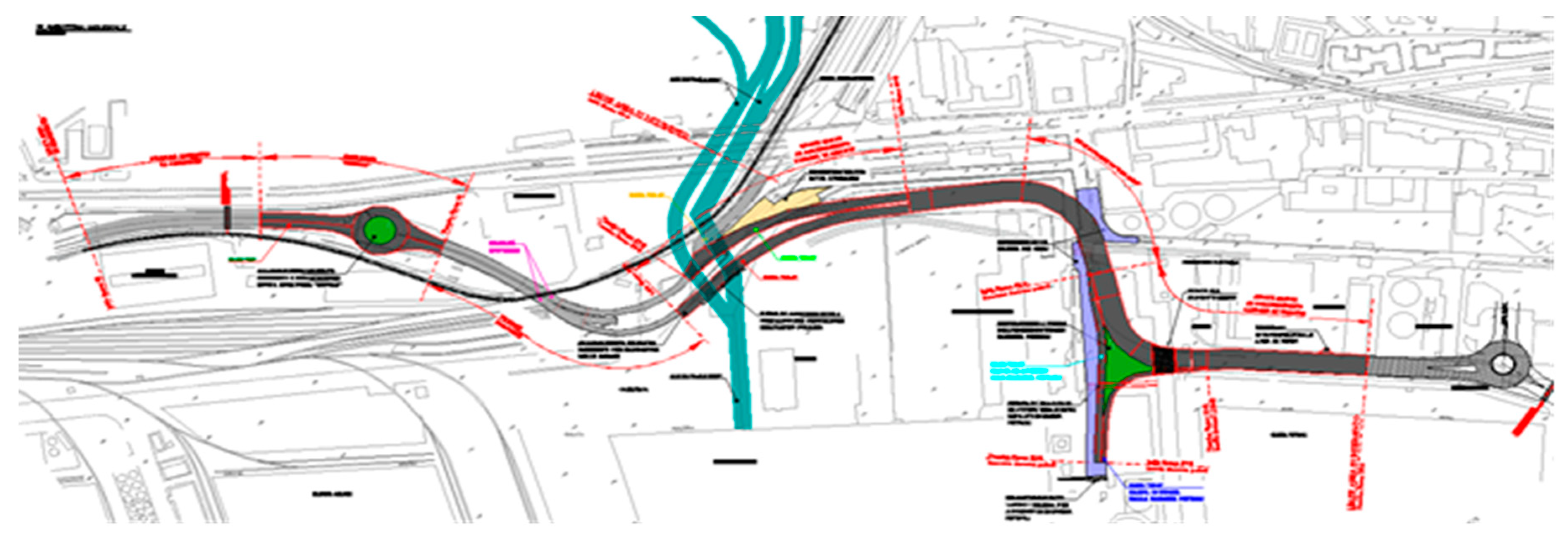
The design solution shown in
Figure 3 aims at the functional reorganization and the sorting of vehicle flows both to the existing west area and to the future eastern dock, through two important road junctions, characterized by roundabout intersections (roundabout “Bausan”—Node “1” and roundabout “Levante”—Node “2”).
In this way it is possible to create an extensive “territorial roundabout,” able to reconnect the docks with each other, to optimize internal connections, and to the motorway network, thus avoiding the overlap of vastly different flows on the urban road network. The two roundabout junctions will allow vehicles coming from the large motorway network and accessing the Bausan gate or the Levante gate to make the necessary reversals, optimizing the flows in transit and eliminating the various points of conflict with the city road network.
The territorial insertion of the two nodes still requires a local reorganization of the various components present in the area of the current Bausan customs gate, in the Vigliena–Darsena Petroli area as well as in the points of contact with the urban road network, outside the perimeter of the port area. From this local reorganization, as well as from the interfering elements present in the area such as the artifacts under concession or the presence of the pipelines of the oil pipe bundle—which from the dock are directly connected to the coastal deposits and the oil area of Naples East—the plan-altimetric drawing of the route was produced.
The design solution consists of a series of elements, main or accessories, necessary for the creation of the connection and its insertion in the area’s viability, for a total intervention of about 1.5 km in length, which covers an area of 45,000 sqm.
The particularity of the topographical context and of the interferences present required the redefinition of the project layout, with the identification of a new path capable of maintaining a good level of balance between the following needs:
Increase the transport capacity of the infrastructure, characterized by a “special purpose” road, due to the heavy traffic volumes present, with a road section consisting of 2 + 2 lanes (2 for each direction of travel);
The need to circumvent or bypass the buildings, the network works and the interferences present, while at the same time connecting to the roads of entry and exit from the motorway network without additional works, so as to limit intervention costs;
The obligation to completely bypass the current oil and pipe bundle, at a level close to the current campaign plan, keeping it in full operation and reducing the size of the containment works;
Minimize and contain the volumes necessary for the formation of the embankment and the excavation volumes, since they are works falling within SIN areas for which delicate and complex land reclamation and characterization works are required;
The desire to maintain a certain balance between contained longitudinal slopes (maximum slope in the order of 4% given the significant incidence of heavy vehicles in transit) and the need to create intersections with entry and exit ramps to the oil and connecting dock.
The result is a very fluid and user-friendly horizontal-vertical combination, avoiding defects in the optical perception of the track that could compromise safety and allowing to travel along the project road axis at low and very close speeds to the project ones (40 km/h).
The solution is well supported by the longitudinal configurations that characterize the remaining branches, creating a solution of longitudinal continuity in the direction of the New Levante area. The presence of levels in altimetric continuity that avoid the formation of vertical connections, effectively eliminating the problem of forming bumps or bags and therefore of contacting the vehicle on the road surface, increasing the safety distance, and therefore stopping the vehicle.
After a deepened study of the project documentation provided by Engco S.r.l., the case study was digitalized in the main steps as follows: (a) modeling 3D corridor; (b) modeling guardrails; and (c) modeling retaining walls.
3.1. Modeling 3D Corridor
The 3D model was carried out using the Autodesk® Civil 3D BIM-tool.
First, the digital terrain model (DTM) was generated in the *.dwg model, by loading the *.dxf model containing the points of celerimetric survey conducted, set in the UTM84-33N system and loaded on the aerial photogrammetric cartography of the Province of Naples.
Subsequently work was carried out on the generated DTM model, introducing new elements in the model itself, in order to enrich the amount of information present. In particular, a series of elements interfering with the project layout have been inserted, modeled and verified, significant for the purpose of verifying and resolving interferences, such as the piles of the motorway viaduct to be under-passed, to connect to the existing road network, i.e., the walls and fences at the perimeter of the petrol tube bundle.
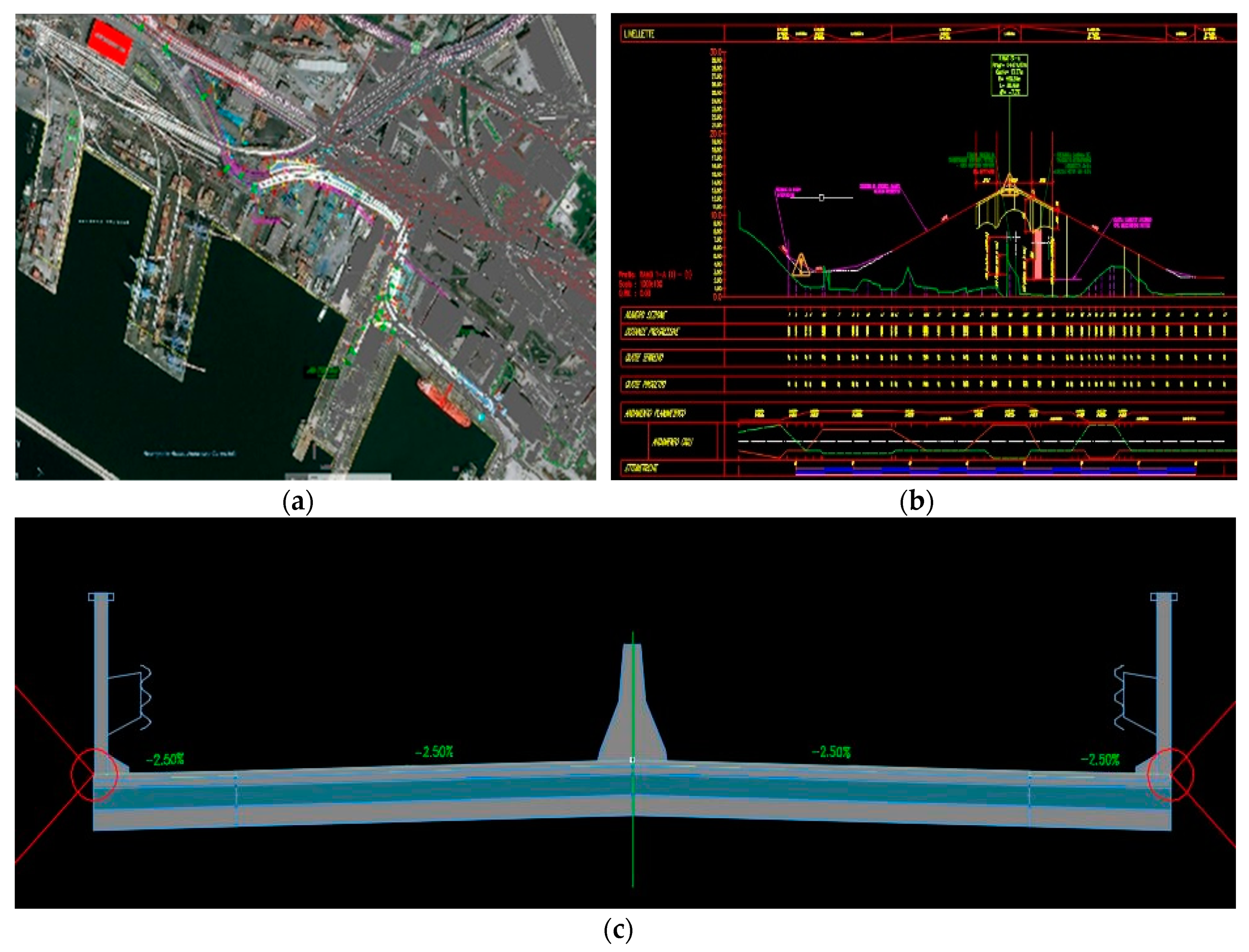
On the DTM, the horizontal-vertical alignment (
Figure 4a,b) was created on the basis of the various hypotheses defined briefly in order to identify the best road layout, able to optimize the progress according to the functional characteristics of the road indicated in the current Road Design Standard and the boundary constraints.
For the assembly templates (
Figure 4c), the Subassembly composer plug-in BIM-tool was used, which allows to create customized and parameterized road elements, according to the current Road Design Standard and the different design characteristics through the alignment.
Subsequently, the 3D corridor developed in Civil 3D was implemented within Autodesk ® Revit for the modeling of major works of art and completion of the project, such as customs buildings, surveillance gates, fences and building works, hydraulic and plant engineering.
Then, in Autodesk ® Navisworks, the different design disciplines were verified and coordinated, through subsequent reviews and resolving or accepting the various clashes detection.
3.2. Modeling Guardrails
Using the available library, guardrails were added in the 3D model by varying the class type (H3 and H4) depending on the installing position through the alignment (roadside and bridge side guardrail).
However, the Civil 3D BIM-tool does not allow to parameterize the elements with additional information, directly connected to the model, such as manufacturer’s technical data sheets or other parameters and information useful both for project development and for the management of the template.
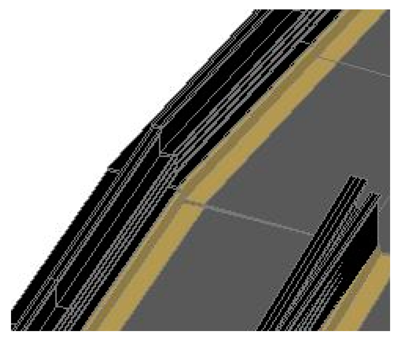
In addition, guardrail extrusion is defined along the path defined by the central axis, returning also for the uprights an extruded solid for the entire route and not for single elements.
Consequently, the resulting extrusion is not as linear as the road alignment, but rather uneven as shown in
Figure 5, without the possibility of inserting special pieces of the guardrail, such as the initial or final element, or the special piece from the roadside guardrail to the bridge side guardrail.
Additionally, this modeling does not allow the user to extract from the volume of the solid useful information for the calculation, as the different fee structures invariably involve an element of cost per linear meter of development, depending on the guardrail class or the type of attack on the foot.
A way to parameterize for the 3D solid created in Civil 3D is by importing it into the Autodesk ® Revit BIM-tool, transforming the Civil 3D output into a mass model. This causes several problems related to:
Loss of geometries, whereby Revit cannot transform certain elements into a mass model, transforming solid elements into three-dimensional surfaces and faces, but losing some mass properties;
System crash, with no import, when the solids are too complex to be transformed into mass models.
In order to avoid the loss of information, it is possible to “link” the Civil 3D model in the Revit environment through the “link” function. This allows the user to have the complete visualization of the corridor and to be able, in the Revit environment, to model with the referenced snap. At the same time, since the corridor is a linked element, it is not possible to parameterize the elements generated in Civil 3D in the Revit environment. In addition, it is not permissible to use the linked element for adding furnishings or characteristic objects. This means that the modeling must be carried out at that point, introducing new control elements, but losing any type of control deriving from modifications of the road layout in Civil 3D. In this case it is necessary to make local and manual modifications of the objects modeled in Revit, adapting them to the new characteristics of the three-dimensional model of the road layout.
Accordingly, the authors began investigating the optimal procedure for modeling guardrails in the Revit environment even if there are no specific families to model typical objects belonging to a road section.
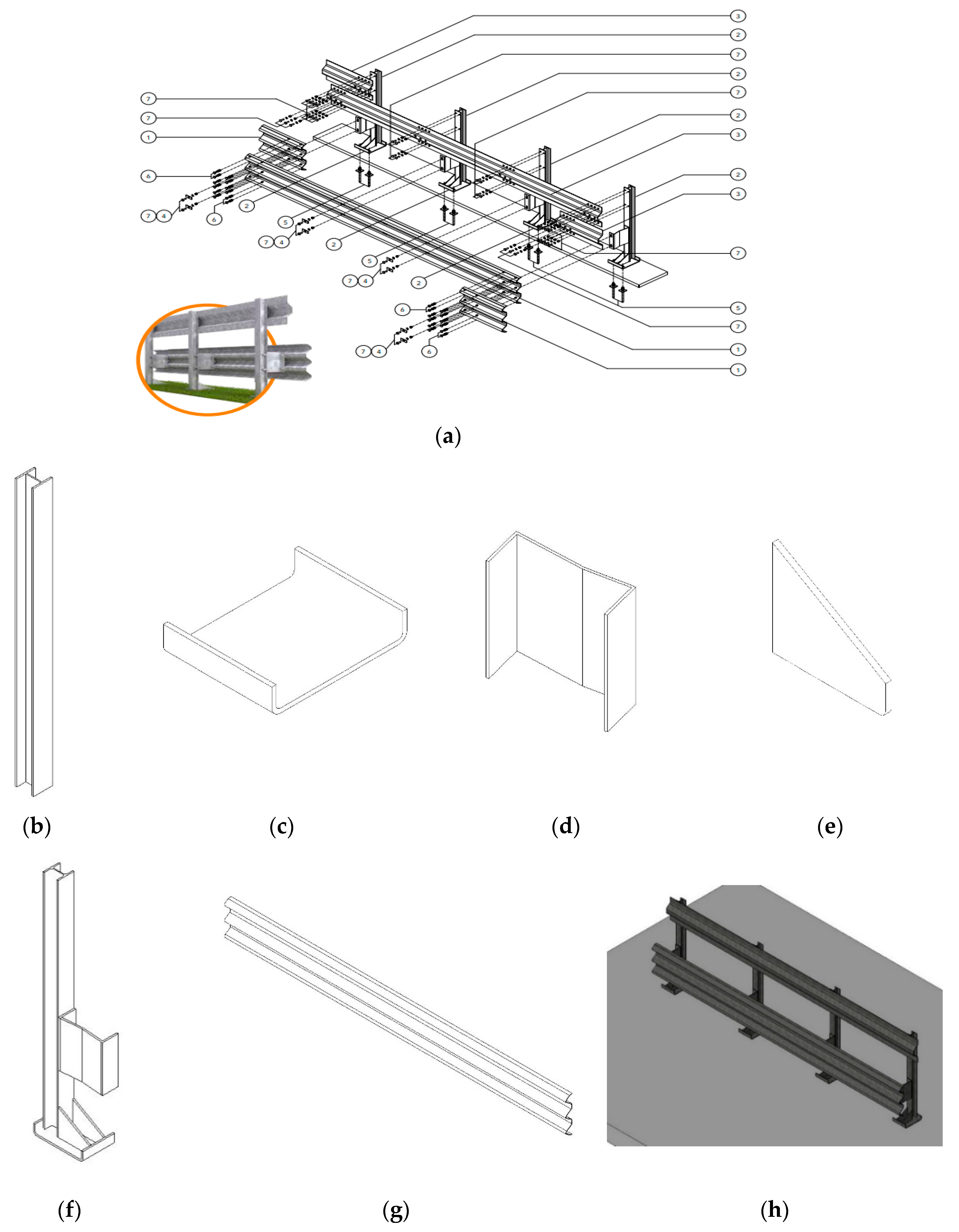
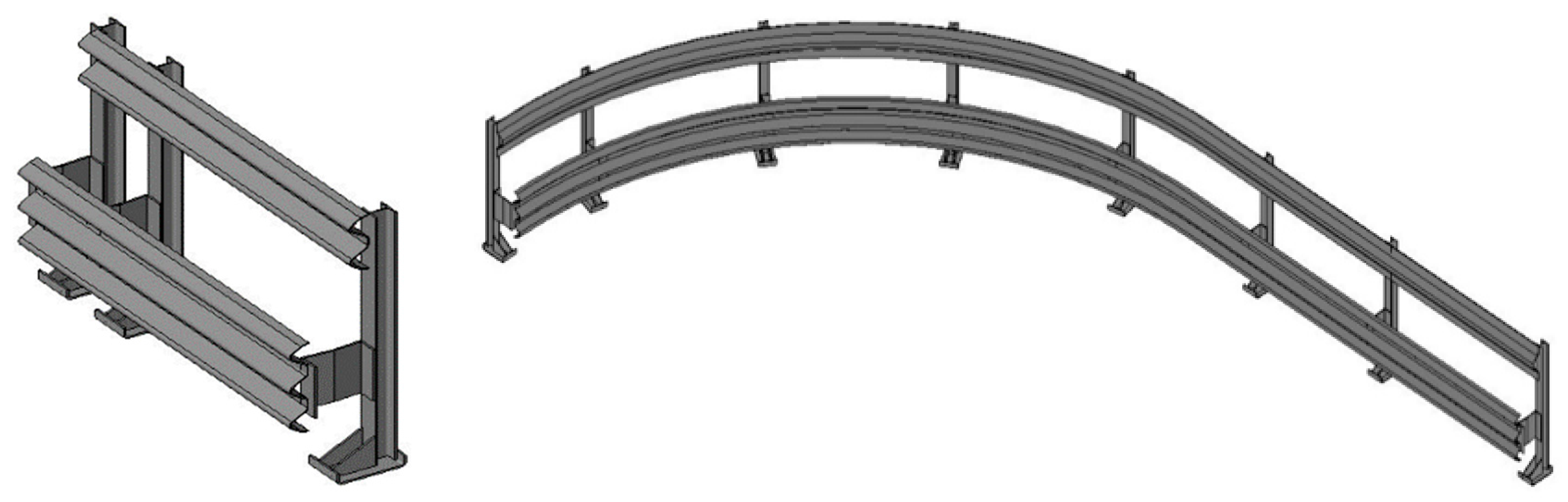
The steel bridge side guardrails are ribbon-shaped elements inserted laterally to the road section in order to delimit, protect and correct the direction of the vehicles in case of spillage. To take into account the geometric parameters of the various elements that make up the bridge side guardrail, the authors referred to the class H3 3-waves guardrail for bridge W4 (
Figure 6a), produced by the Marcegaglia Company, well-known on worldwide market.
The “generic model” family was used for modeling each component of the bridge side guardrail shown in
Figure 6, obtaining the maximum level of detail. Once the model has been linked from Civil 3D, it is necessary to carry out the following:
The manual insertion of each of the individual “upright” objects, characterized by the guardrail support pole, orienting the element with vertical axis and front elevation parallel to the roadside from time to time;
The modeling of the additional components (bolts, plates, spacers, etc.) using the upright as a host element to which to connect the individual objects;
The generation of an extruded object, having a cross section equal to the wave band, along a trajectory that follows the different uprights, so as to reconstruct the lateral trend of the bridge side guardrail for the different cross sections;
The addition of any and further elements, such as diagonal bands or other characterizing element the user wants to insert, in order to make modeling more realistic.
All the components where then merged as a single one, as shown in
Figure 6h.
This modeling method involves some critical issues as follows:
High modeling burden, having to insert each component as an object of the generic family, to then insert each component individually in the three-dimensional model;
Considerable weighting of the model itself, deriving from the presence of the large number of components present in relation to the length of the road section;
Need to make numerous changes in the case of even minor changes to the road surface, as the inclusion is not tied as host to the link of the connected Civil 3D model.
During the generation and control of the clash-detection, this involves, the resolution of a possible high number of conflicts that cannot be accepted generally, with the need to make numerous modifications and additions to the model itself.
On the other hand, this modeling allows the user to have:
The maximum level of detail permissible, through the summary or detailed modeling of all the construction components of the bridge side guardrail;
Complete control of all the characteristics of each of the elements, with the possibility of parameterizing all the elements present including all the special pieces or singularities present along the path, such as the thickening to protect foreign bodies present in the deflection width of the guardrail;
The possibility of having all the information for the accounting of the guardrail due to a direct and detailed schedule, useful both for design purposes, from the point of view of technicians, for execution, for cost control and assembly by companies construction, both constructive, with suppliers in possession of complete control of the outgoing product.
Thus, another way for modeling the guardrail was determined.
The guardrail is an element that has a predominantly linear development, with uprights that must be installed vertically, and which must dynamically follow the design not of the road axis, but the profile of the lateral edge, dependent not only on the longitudinal profile but also by the transversal trend of the road surface. It was therefore considered part of the “railing” family for modeling purposes.
This element develops mainly along one direction, consisting of vertical balustrades and horizontal currents, which can be modified and customized.
Based on the dimensional characteristics of the technical data sheet, “balustrade” objects such as the uprights of the guardrails were created, inserting a series of additional and detailed elements inside the object, such as the spacer plates or the fixing pins.
The sections of the two-wave or three-wave bands were also created from the profiles of the currents according to the guardrail type. By changing the settings of the railing parameters, it was possible to define the pitch of the uprights, the presence or absence of additional terminal or initial elements. The results are shown in
Figure 7.
This modeling presents the following critical issues:
For insertion purposes, the object must be linked to a host element, consisting only of an element from the “floor”, “ramp” or “staircase” family, or alternatively, to a 3D polyline representing a line of development. This means that in order to connect the guardrail to a road layout imported from Civil 3D as a link, it is necessary to either recreate a “floor” element in Revit, exactly superimposed on that of the linked file, or a three-dimensional polyline, to be used to then connect the guardrail objects;
The need, in case of horizontal-vertical alignment’s changes, to modify and adapt the floor element’s alignment or of the space trajectory’s polyline;
It is not possible to insert special elements or intermediate singularities, unless you disconnect the different “railings” inserted, and then proceed manually to insert this singularity.
On the other hand, the insertion of the guardrail according to this criterion has the following benefits:
The insertion takes place dynamically and completely, easily following the trajectory of the side edge of the road section, adapting to possible plan-altimetric variations. The wave bands and the orientation of the uprights automatically adapt to the progress of the road pavement;
The family allows the insertion of special initial and final pieces of the guardrail, always modeled as a balustrade and inserted in the family among the object management parameters;
The Revit model is lighter and easier to manage, characterized by fewer objects inserted inside it and less possibility of errors, as correct changes to the host element do not lead to errors in the insertion of the guardrail;
For computational or future management purposes, it allows to have the necessary measurement parameters, possibly deriving, through a suitable schedule, other numerical values depending on the length, such as the number of uprights, number of bands, special elements of start and end of guardrail or other.
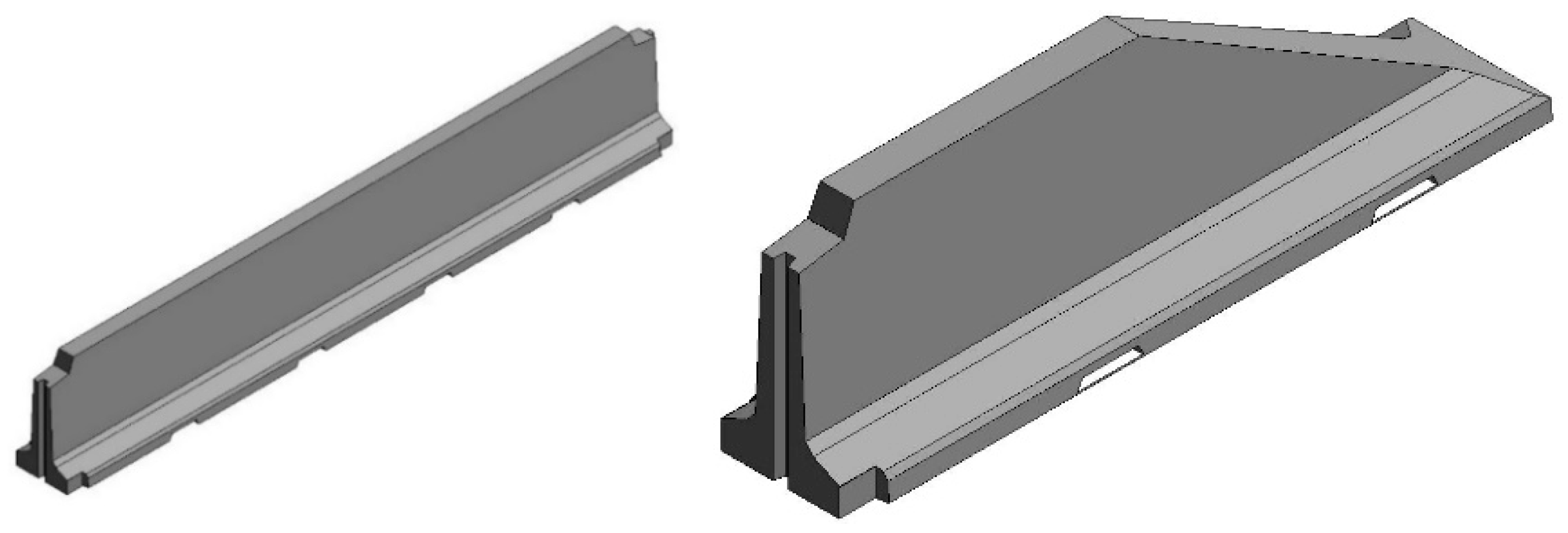
For the New Jersey type protection elements, the same criterion was adopted, the object has the same characteristics described above, both in terms of functionality and parameters, since for the purposes of computation, the only reference parameter is the linear development.
New balustrade families have been created by modeling the New Jersey and represent the special piece at the beginning and end of the guardrail, as shown in
Figure 8.
In a new project model, the railing system family was duplicated and customized:
In the current settings, the items present have been deleted;
In the balustrade settings, the existing entries have been eliminated and the imported balustrade family representing the New Jersey has been inserted;
In the settings of the upper rail a circular profile has been inserted and set representing the rolled linking bar of the single New Jersey.
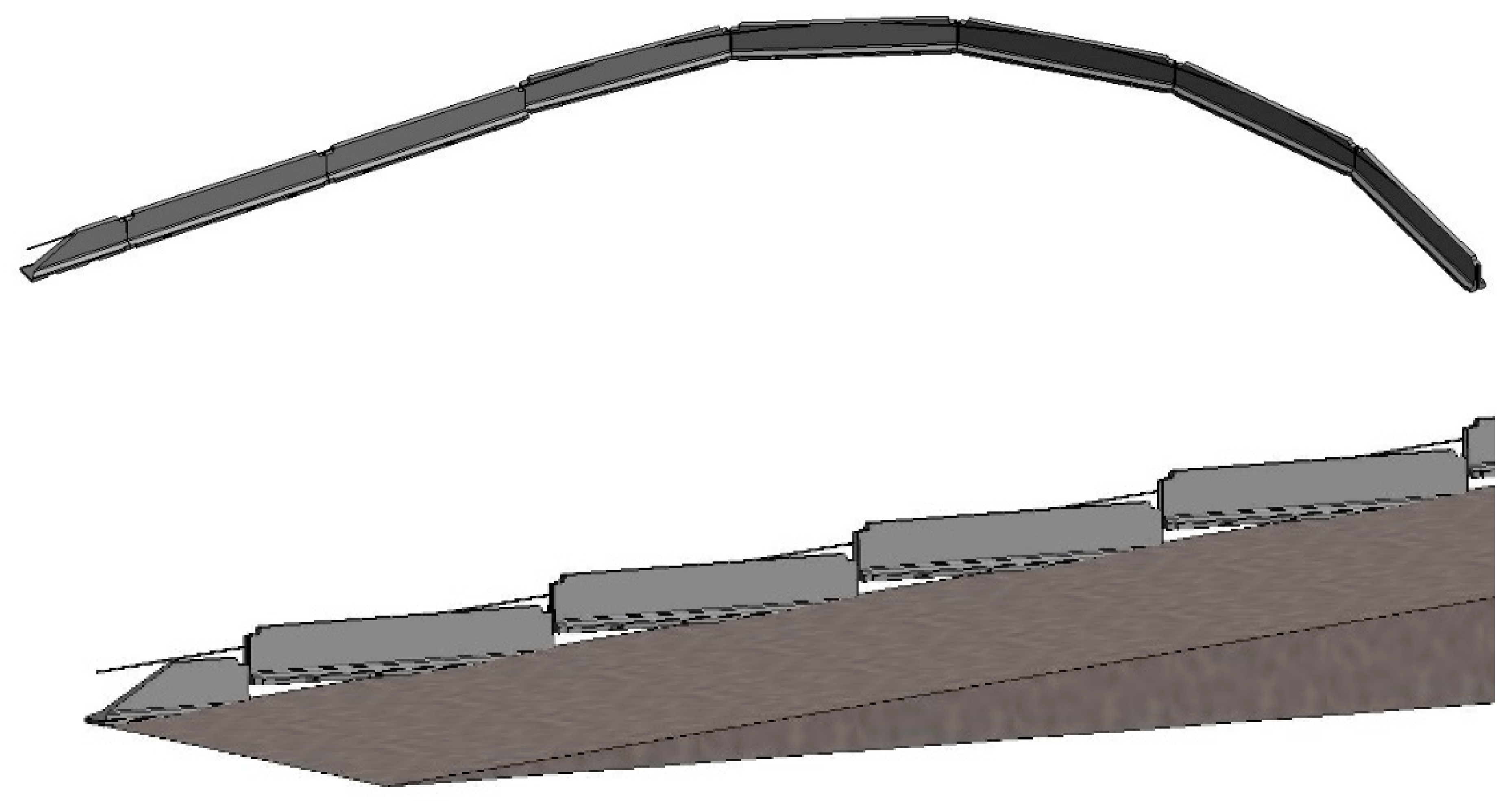
With this type of element, in addition to presenting the pros and cons illustrated previously with the bridge side guardrail, in the event that the object is inserted on inclined surfaces, the balustrade inserted vertically and not orthogonally to the support surface, therefore graphically the elements are visualized as a consecution in steps as shown in
Figure 9.
3.3. Modeling Retaining Walls
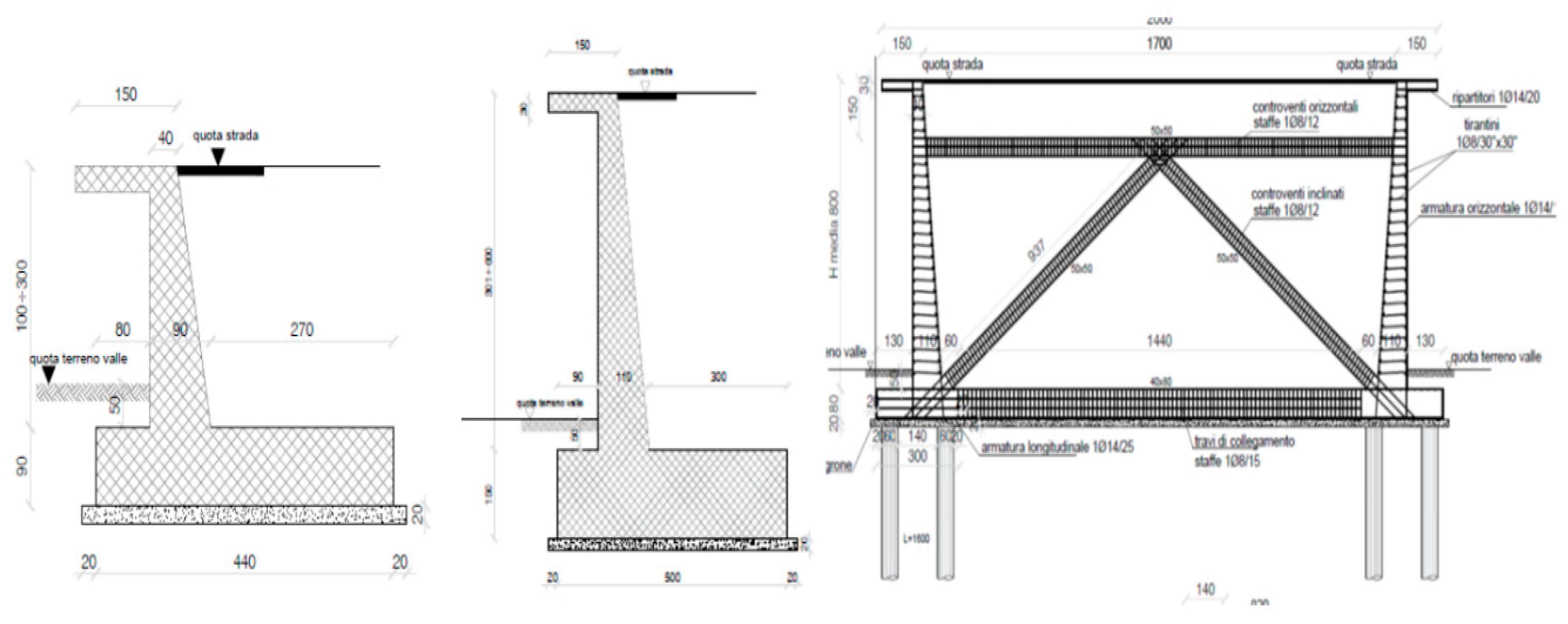
For retaining walls, the case in question involves a different type of wall as the height of the road section varies with respect to the surface of the countryside, i.e., type 1 wall with a height of 1.0 m to 3.0 m, type 2 of 3.0 m at 6.0 m, type 3 >6.0 m as shown in
Figure 10. The element must be such that the development of the section follows the plan-altimetric trend of the road layout.
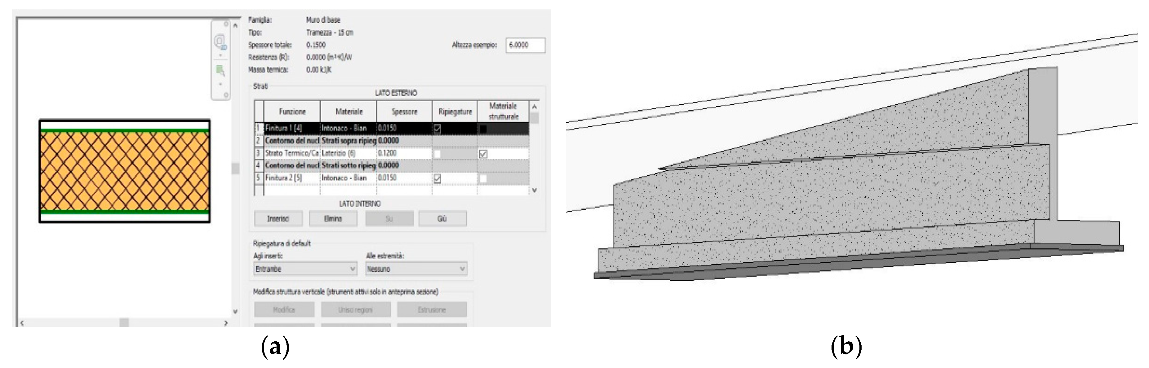
The first hypothesis that has been posited is to model the work directly in Revit, having as reference the progress of the linked profile. In this case, we are looking for a family category that can support the framework. The first attempt was to use the “wall” family to take advantage of the insertion with host elements on reference surfaces, but this family only allows the layering and modification of the thicknesses of the individual layers but not the customization of the wall profile (
Figure 11a).
Then, the construction of the wall profile was created with the “overlapping wall” function in which different versions of the wall were created for each thickness of the supporting wall and subsequently they were superimposed to create the section of the wall.
In this case, the characteristics of the wall family are used, i.e., the lower and upper hosts, and in the parameter settings, the central element as designed is chosen as the variable part of the height. As long as there is a defined height, the element respects the proportions and changes the part set in the parameters as variable, while if the “associate upper part” command is used, which allows the user to adapt a wall to the upper surface, the BIM-based tool does not vary the parameter set as a variable but extends the head surface of the wall by altering the set dimensions or cutting the object as shown in
Figure 11b.
One option to correctly model a retaining wall that follows the horizontal-vertical road alignment is to use the generic “metric mass” family, defining the sections and positions them along the path and creating a solid extrusion.
This operation returns a surely correct result as a model of the solid, reproducing both in terms of geometry and as the possibility of inserting the information content, but there is no possibility of being able to parametrically connect the object to the linked link of the road section.
Therefore, a variation of the geometric characteristics of the road layout would entail the modification of the element section by section, therefore the non-versatility and adaptability.
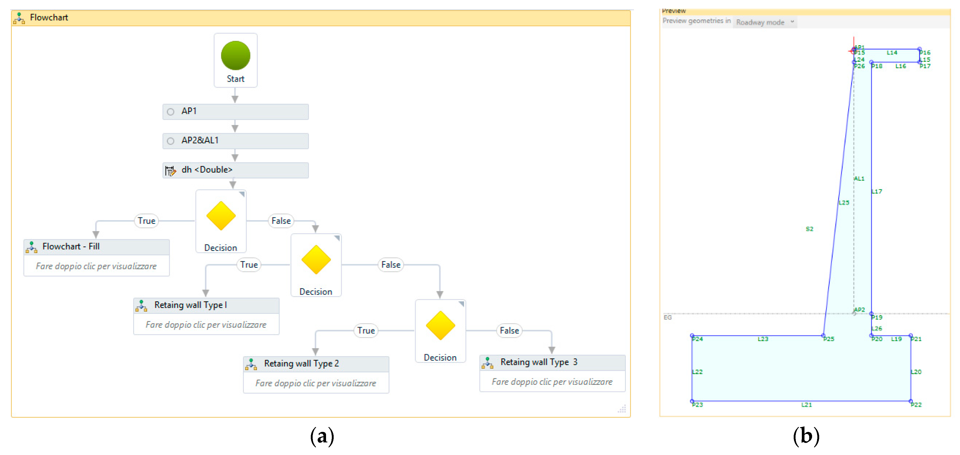
To have a dynamic and parameterized modeling, the retain walls were modeled directly in Civil 3D with the subassembly composer application.
In subassembly the main flowchart (see
Figure 12a) has been set with decision variables that change as the boundary conditions vary. In the case in question, the section changes dimensional characteristics as the distance between the road surface and the ground surface changes.
Then, decision variables were inserted based on the value of the height variable created. Up to a height of 1.0 m, the element inserts the embankment with a defined slope, which in the design case is 33%.
Once the 1.0-m distance is exceeded, a new decision variable and a flowchart for the construction of the element are inserted, so that for heights between 1.0 and 3.0 m the element creates the type 1 section, for heights between 3.0 and 6.0-m type 2 and above 6.0-m type 3. The result is shown in
Figure 12b.
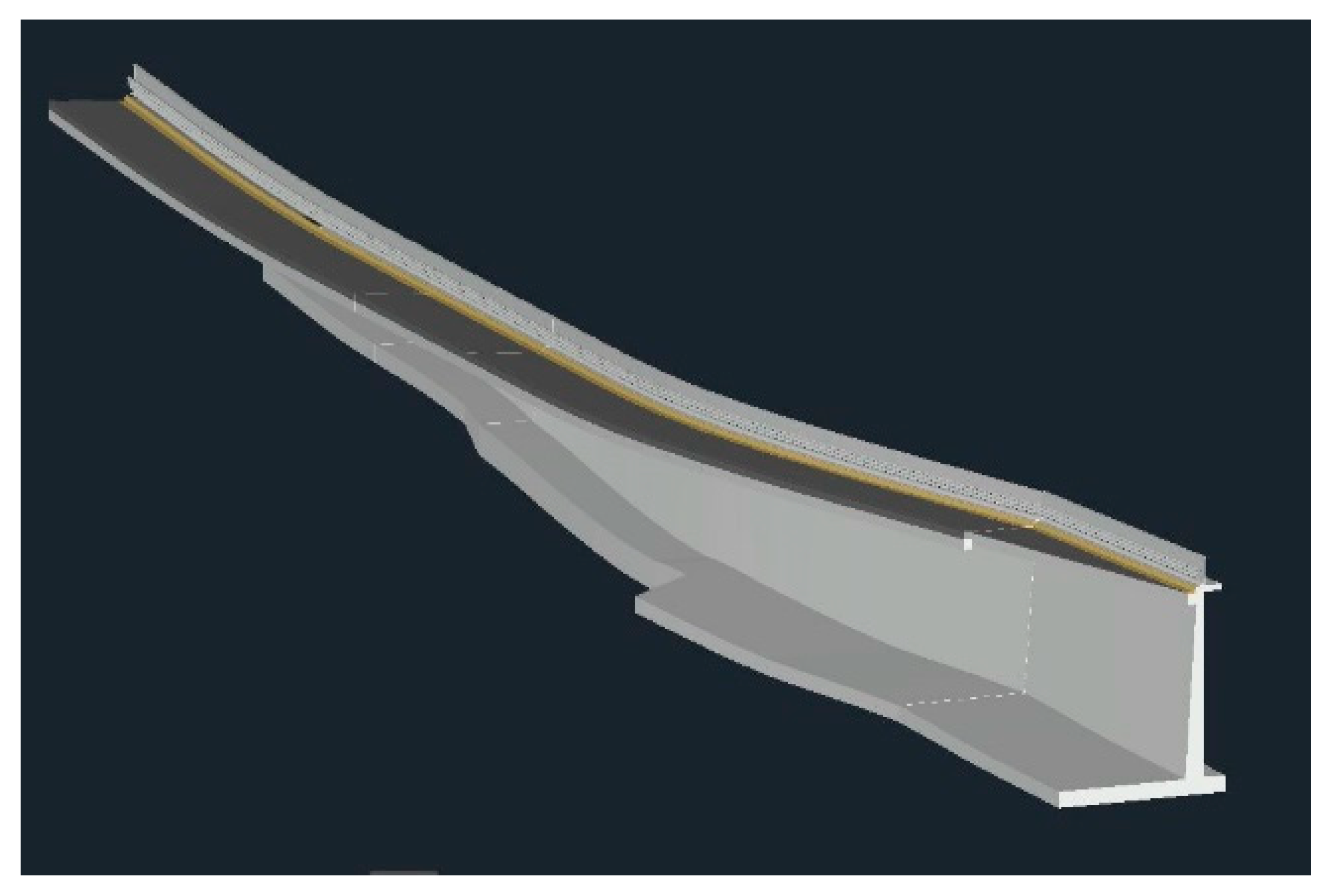
Once the creation was complete, the object was loaded into the Civil 3D file, inserted in the assembly type, and uploaded the 3D model. As shown in
Figure 13, the retaining wall modeled follows the development of the road alignment, adapting its shape according with height changes.
However, difficulty remains in using the object to insert the reinforcement in Revit as it is read only as a link. Therefore, to add this information content, the user only needs to connect technical data sheets to the object showing the list of armor in Civil, or reshape the object in Revit.
4. Results
The case study of the project for the reorganization of the internal road systems of the Harbor of Naples highlights some critical issues of the use and application of the BIM process in the infrastructure field, evaluating the actual iteration between the BIM-based tools of the same software-house.
Civil 3D represents an excellent modeling tool for road design, but in fact it does not allow to generate full interoperability with other programs in the BIM environment. From an engineering perspective, the error and the approximation committed are acceptable, but the internal modeler generates an approximate and inaccurate solid, for which the defects are highlighted in comparison with other graphics management software. It is possible to customize different properties for road components, but not to parameterize them with additional external elements (cards, attachments, etc.) or internal elements (schedules, construction details, etc.) according to BIM standards. Furthermore, Civil 3D obliges the user to link the various elements to the reference progressive ones, but it is not possible to insert a dynamic model of the objects.
Therefore, Civil 3D cannot be used for a complete management of the road model, a management that often involves the implementation of major, minor, or accessory works. Although there are several connection options, Civil 3D, Infraworks and Revit still have numerous shortcomings of interoperability with each other—firstly, the absence of plug-ins or functions that correctly connect the models created in Civil and Revit. Despite the use of link through IFC file, it is not recognized in the Civil 3D—Revit step, with the consequence of it being unable to perform a parametric and interactive modeling, while the insertion in Revit as a link of the models in Civil 3D involves the loss of data and the need to perform additional modeling and operations.
The interoperability problem could derive from different calculation codes, which contemplate a different conception of the model:
Civil 3D requires the presence of a single topographic reference surface, with a variable course, to which the generation of the model can be linked, thus identifying “excavation” and “carry-over” elements according to the relative position of the road surface and the section transverse type;
Revit, conceived for works with a predominantly vertical development, uses a model linked to levels, to which objects are connected to the foot and in elevation, identifying the relative position of the topographic surface with respect to the story of the floors, in which the “0” level is represented by the deepest foundation plan.
An alternative for managing the federated model is the use of Navisworks, since it is a more open and versatile BIM-based tool, which allows to have a complete graphic display, but which is not designed for such use. Navisworks is open to different formats, allowing the user to manage and check for interference from a geometric point of view but does not allow the user to parameterize or manipulate objects.
5. Discussion
Analyzing the different problems highlighted in the manuscript, and comparing the different aspects detected, a series of extremely important evaluation elements emerge. First, remaining in the Civil 3D environment, the presence of the guardrail must be modeled as the solution requires, as contemplated in the various road safety checks, and therefore the absence of this element implies an underlying design error incompatible with the process.
This modeling, however, is an end in itself, as it is not possible to use or scale it in the BIM environment: the presence of the solid of the guardrail entails a weighting of the linked or imported model, with the generation of unnecessary elements, capable of generating errors and confusion in the modeling process in Revit. Before analyzing the pros and cons of the different models in the Revit environment for guardrails, it is necessary to carry out an evaluation of the end user and the objectives, according to at least two cases:
The model is aimed at computing and managing “every single element present,” as in the case of guardrails producers, on-site suppliers or the managing body or its concessionaire, who must have complete control of the number of each individual element, in in this case it is necessary to face the burden of modeling for “generic model”, creating, inserting, orienting and generating each of the constituent parts of the guardrail;
The end user represents the designer of the work, the executing company, the managing body or one of his concessionaires, from the point of view of calculations and management, it is possible to carry out a modeling for the “railing family,” inserting in Revit a floor element to be adapted to the road surface, to be used as a host for the connection of the guardrail.
In the first case, the benefit of the model is to generate an advanced construct, in which the exact number is present or which in any case reduces the error committed on the exact valuation of the quantities present. For this reason, this modeling is oriented towards the producers or suppliers in place, for which the production process control starts from the acquisition of raw materials to end in the actual installation of the components, and requires, especially for large quantities, an accurate count.
This clearly includes the management, the owner or one of its dealers, since it is in fact the ultimate user of the work itself, who will be able to use this amount of information both during the useful life of the work and to evaluate its disposal, reuse and functional adjustment at the end.
The maximum level of definition of this model can certainly be reached during the us-build phase of the work, a time moment in which the work no longer undergoes changes since it has been completed, and for which it is possible to detect exactly the number of elements of which consists.
This, however, involves an inconsistency with the timing and processes of the supplier control, which sees a model and its quantities evolve continuously, possibly changing continuously the process of quality and production control.
This modeling, on the other hand, appears too expensive in terms of defining the model and the number of hours of work, in the design phase of the work itself, in which the number of variables and the presence of unforeseen work, in fact make such a modeling useless, subject to constant adjustments and not very dynamic.
The second case lends itself well to a streamlined, dynamic and interactive modeling, typical of the design and execution phase of the work. Once the library has been created with the different types of barriers present, the insertion takes place in a fluid and dynamic way, with excellent graphic rendering, and allows you to generate, through Revit schedules, the information necessary for the computational phase, to carry out a simulation of realization, so as to verify the congruence of the contractual times.
The same model, transferred to the performer of the work, can be easily scaled and implemented to take into account all the changes or variations during the work, due to unforeseen or other effects. In this way, the final us-build model can be delivered to the manager or owner for the next useful life, providing the information necessary for the management of the work.
The model certainly has some margins of error, deriving from the indirect calculation through the use of schedules, such as for example the calculation of the number of poles or linear development of the waves, as the model does not contemplate possible wave overlaps during the installation phase, or pole refining.
The computation and modeling burden must be discounted through the continuous adjustment of the flooring surface, to be used as host, or by cutting the barrier generation polyline into segments, in the event of interruptions or special pieces to be inserted.
Using a dualism with the structures, the creation of an application capable of generating a “floor” element from the Civil 3D model, created from the solid road surface to be imported into Revit, would entail a greater degree of control and a shorter development time of the model, thus reducing the possible error.
6. Conclusions
BIM software files are based on the IFC (Industry Foundation Classes) standard, i.e., an object-based file format with a data model developed by buildingSMART to facilitate interoperability.
First of all, IFC standards are well developed with regard to vertical structural elements, i.e., columns, pillars, walls, and architectural elements, i.e., windows, doors, railings, stairs, roofs, etc., but on the other hand the development of standards referring to horizontal elements, such as those that constitute road infrastructure of all kinds, is still in progress.
Currently, the BIM maturity level within the infrastructure field correspond to an intermediate grade, because interoperability is not yet error-free and not all data is exported when using standard file formats.
There are critical issues in the evaluation of the master model which must cover all disciplines and models; for vertical works a federated model created with Revit is used, but this is not possible in the case of horizontal works. Navisworks could be used since it reads all the models and allows to have a complete graphic visualization, even if it is not designed for this use.
The Infraworks software was created by Autodesk as a central model on which to carry out the preliminary design and extend it to the executive, communicating with Civil and Revit, but it is still not efficient and is continuously updated by the house to correct and enhance the functions.
The methodology used aims to provide, as a first step, a procedure for the practitioners on how to manage these modeling problems faced repeatedly in the design phase, being confused on what to do in the absence of specific indications in the current state-of-the-art.
Both, the critical points observed and the related resolution method, want to represent a valid contribution for us and other research groups that will read this research paper, to mark the second further step of the research aimed at identifying simplified methodologies for the development of ad-hoc IFC for assembly components that could streamline the amount of work as well as the interoperability between the different calculation codes and software houses.
Most importantly, the continuing collaboration between academia and industry is required to mitigate most challenges and to realize the full potential of BIM for transportation infrastructure.


