A Minimal Input Engine Friction Model for Power Loss Prediction


Department of Mechanical and Aerospace Engineering (DIMEAS), Politecnico di Torino, 10129 Torino, Italy
*
Author to whom correspondence should be addressed.
†
These authors contributed equally to this work.
Lubricants 2022, 10(5), 94; https://0-doi-org.brum.beds.ac.uk/10.3390/lubricants10050094
Submission received: 30 March 2022
/
Revised: 26 April 2022
/
Accepted: 4 May 2022
/
Published: 12 May 2022
(This article belongs to the Special Issue Automotive Tribology II)
Abstract
:The minimization of friction losses in internal combustion engines is a goal of primary importance for the automotive industry, both to improve performance and to comply with increasingly stringent legislative requirements. It is therefore necessary to provide designers with tools for the effective estimation of friction losses from the earliest stages of design. We present a code for the estimation of friction losses in piston assembly that uses semianalytical models that require only strictly necessary geometric and functional inputs for the representation of components. This feature renders the code particularly suitable for the preliminary design phase. Furthermore, models ensure reduced computation times while maintaining excellent predictive capabilities, as demonstrated by the numerical–experimental comparison.
1. Introduction
Rising fuel costs and increasing limits in environmental legislation render improving the mechanical efficiency of internal combustion engines (ICEs) a topic of paramount importance for the automotive industry [1]. The efficiency of ICEs is severely limited by the tribological behavior (i.e., friction, wear) of various engine components, with detrimental effects on fuel consumption and emissions [2]. The piston group is one of the major contributors to the friction power loss and failure of ICEs, accounting for 40% of total engine friction losses [3].
The interface between piston rings and the cylinder liner is of primary importance [4]. Many factors are related to the tribological behavior of this interface, with the main ones being the ring profile [5,6,7,8,9], ring height, and axial depth [10,11], ring tension [12], surface coatings [13], and working conditions [14,15,16]. In this paper, similarly to [14,15], the axial symmetry of loads and geometry of the system are exploited. The piston ring is treated as a dynamically loaded reciprocating bearing, considering the action of sliding and squeeze motion. A numerical procedure is then developed to obtain cyclic variations of film thickness, frictional force, power loss, and oil flow across the ring.
Another relevant contribution to ICE friction losses comes from the interaction between piston skirt and cylinder liner. Even though the piston is centred by the ring pack, unbalanced forces and moments acting on it in a perpendicular plane to the wrist pin axis, and containing the thrust and antithrust sides, cause small translations and rotations within the defined clearance with respect to the liner [17,18]. These motions are secondary piston motions and can be defined by means of eccentricities at the top and bottom of the piston skirt [19,20,21]. Theoretical and experimental studies for the evaluation of friction losses in internal combustion engines due to secondary piston motions were summarized by Ciulli [22]. The evaluation of these losses is important in the calculation of the efficiency of the whole engine, since their contribution to overall losses is the second largest after that of piston rings [23]. Hydrodynamic pressure acting on the piston skirt was determined here using a two-dimensional formulation of the Reynolds equation due to the axial and circumferential variation of oil meatus thickness: a finite difference scheme can be applied to solve the 2D Reynolds equation and determine the pressure distribution at the skirt–liner interface.
The final contribution to friction losses in ICEs that is considered here is journal bearings supporting both conrod and crankshaft. In recent decades, there were great attempts to evaluate and simulate the tribological and lubrication performance of journal bearings [24,25,26,27]. Lubrication theory is primarily applied to examine the tribological performance of finite-length bearings [28,29]. In this context, pressure distribution is often defined under an approximate analytical solution of the Reynolds equation.
Modeling the tribological performance of engines is important for two main reasons: first, the development of analytical tools for design evaluation, and second, the development of reliable friction models that can be used in transient simulations of the engine to predict its actual performance. Providing designers with reliable models to predict friction losses is necessary to discriminate the most effective design solutions in minimizing losses. Such models would reduce the need for experimental tests to check the most promising solution. Highly advanced software for the behavior prediction of engine components is now available, and some offer suites to predict friction losses. However, these tools are complex and require a large amount of input data, often including a CAD model of components [30]. This requirement renders the use of these software packages a daunting task during the predesign phase, when there is still much uncertainty on different features.
The purpose of this paper is to overcome this issue by proposing software that can effectively predict friction losses starting from a minimal set of input parameters, i.e., key geometrical dimensions, lubricant data, and operating conditions. The proposed tool cleverly uses a combination of analytical models, basic numerical discretization, and numerical methods to time-efficiently indicate friction losses. This features enables the designer to explore the influence of different parameters and ensures efficient comparisons of different design solutions. The tool, equipped with a graphical user interface, is able to estimate friction losses for key engine components such as piston rings, piston skirt, and journal bearings (connecting rod and main crankshaft). For each component, constitutive model equations are provided with the implemented solution technique. The predictive capabilities of the model are discussed by showing an experimental–numerical comparison on a reference test case.
2. Design Tool Overview
In order to create an easy-to-use design tool for end users, an easy-to-interpret graphical user interface (GUI) was implemented to ensure quick and intuitive data entry, and easy viewing and exporting results. The main menu of the presented tool is shown in Figure 1.
The designer may automatically enter data using an external spreadsheet, so that a large number of simulations can be quickly performed, which is useful for performing parametric studies on the effect of different input data on friction losses on modeled engine components.
As shown in Figure 1, the proposed tool allows for the evaluation of friction forces and the dissipated power for three main subsystems of the ICE: piston rings, piston skirt, and journal bearings (main and conrod).
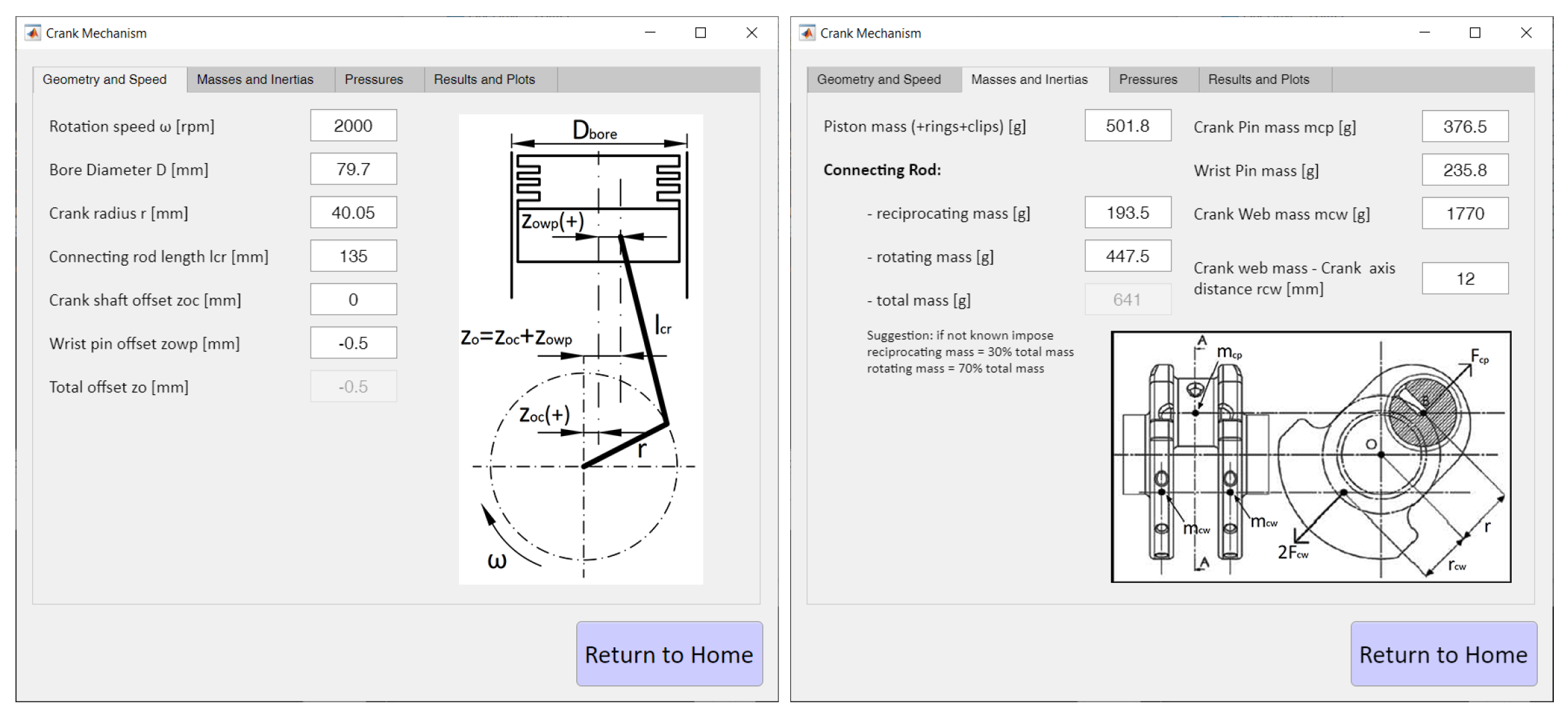
The first tab available to the user, “Crank Mechanism”, allows for the input of geometric and inertial data of the crank mechanism. It is shown in Figure 2, and its inputs are later used by the models of each subsystem.
The layout of the connecting rod-crank mechanism can be one of two types: centered and offset. In the centered configuration, the cylinder axis intersects the rotation axis of the crankshaft and the wrist pin axis. In the offset configuration, the cylinder axis does not intersect the rotation axis of the crankshaft and an overall offset is present in agreement with the rotation direction of the crankshaft when the piston reaches the top dead centre (TDC). Offset cranking is useful as it reduces pressure acting on the connecting rod side and the piston-slap phenomenon. All formulas were developed for offset configuration, i.e., the centered configuration is treated as a special case with null offset.
The design tool also allows for the simulation of two different engine operating conditions: motored and fired. In the case of fired operation, pressure values in the combustion chamber and between the various piston rings can be entered by the user by importing an external spreadsheet.
Input data for each component of the design tool is broken down by type:
- Geometric (and inertial, if necessary) data of connecting rod-crank mechanism.
- Working conditions in the combustion chamber (motored or fired).
- Geometrical data and lubrication conditions of the component under examination.
- Tribological data of the lubricant and the modeled surfaces
- Parameters necessary to the numerical integration method.
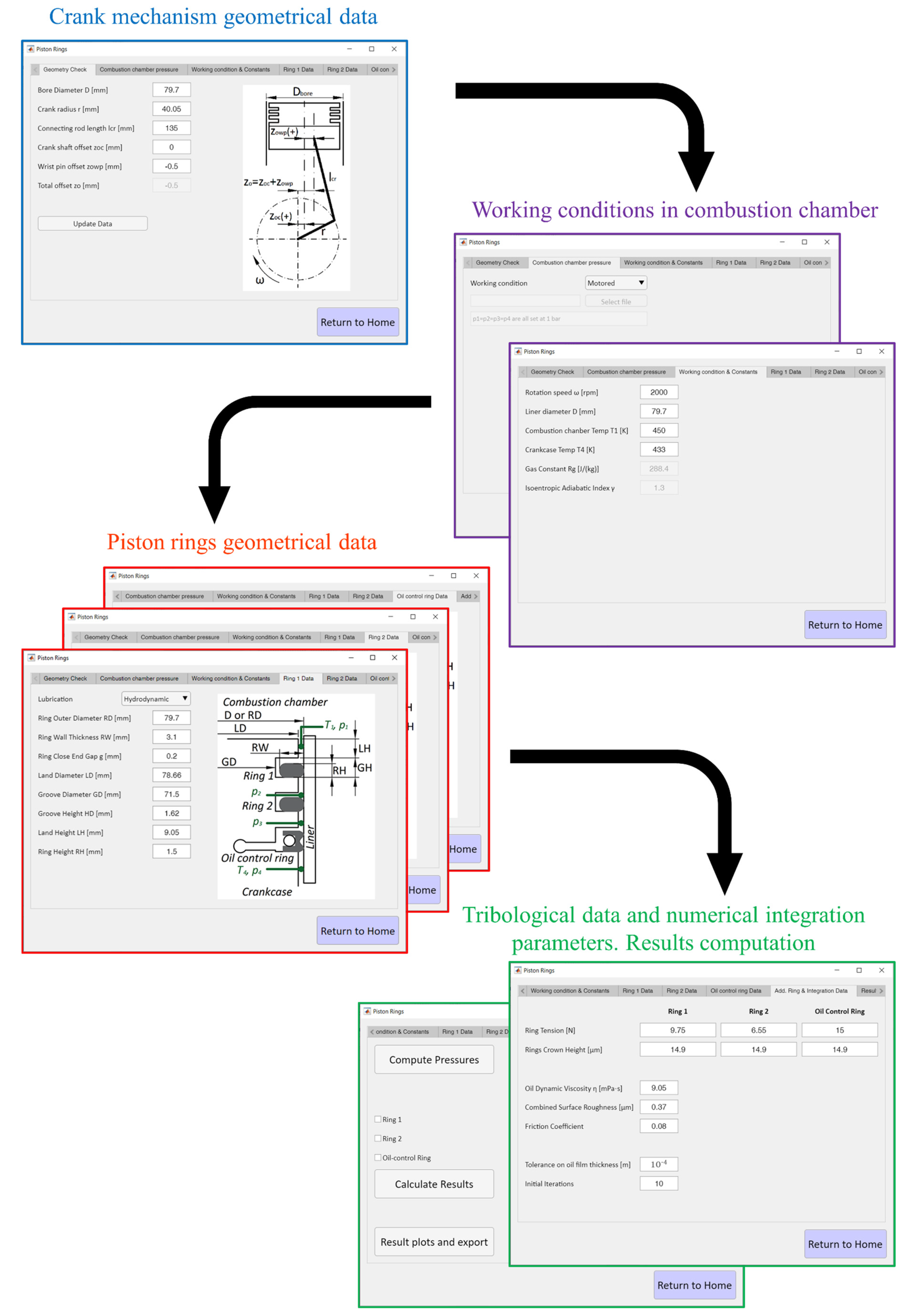
The flowchart for setting up the model is shown in Figure 3, using as a demonstrator the tabs and data needed for the evaluation of friction due to the piston rings.
2.1. Modeling and Numerical Methods
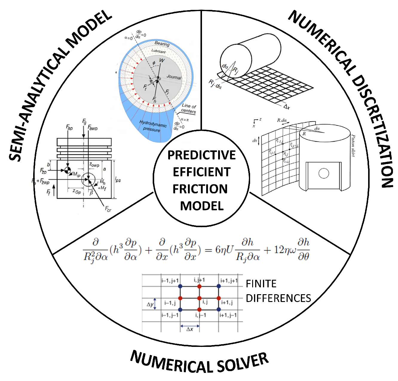
The design tool presented here uses a similar scheme for the different subsystems that it analyzes (piston rings, piston skirt, and bearings). There are three fundamental elements, as shown in Figure 4:
- Necessary semianalytical model to define the relationship between external forces acting on the component, and the pressure and thickness present in the lubricant meatus.
- Numerical discretization (1D or 2D) to solve the Reynolds equation associated with the lubricant meatus.
- Numerical methods such as finite differences to solve the Reynolds equation, and algorithms to link equilibrium equations with meatus thickness h.
To ensure high calculation speed of the code, which allows for the comparison of a large number of different solutions during the initial phases of the design process, we assumed the following:
- crankshaft angular speed is constant;
- lubricant is Newtonian and incompressible;
- oil viscosity and density are constant;
- thermal and elastic deformation of the components are neglected.
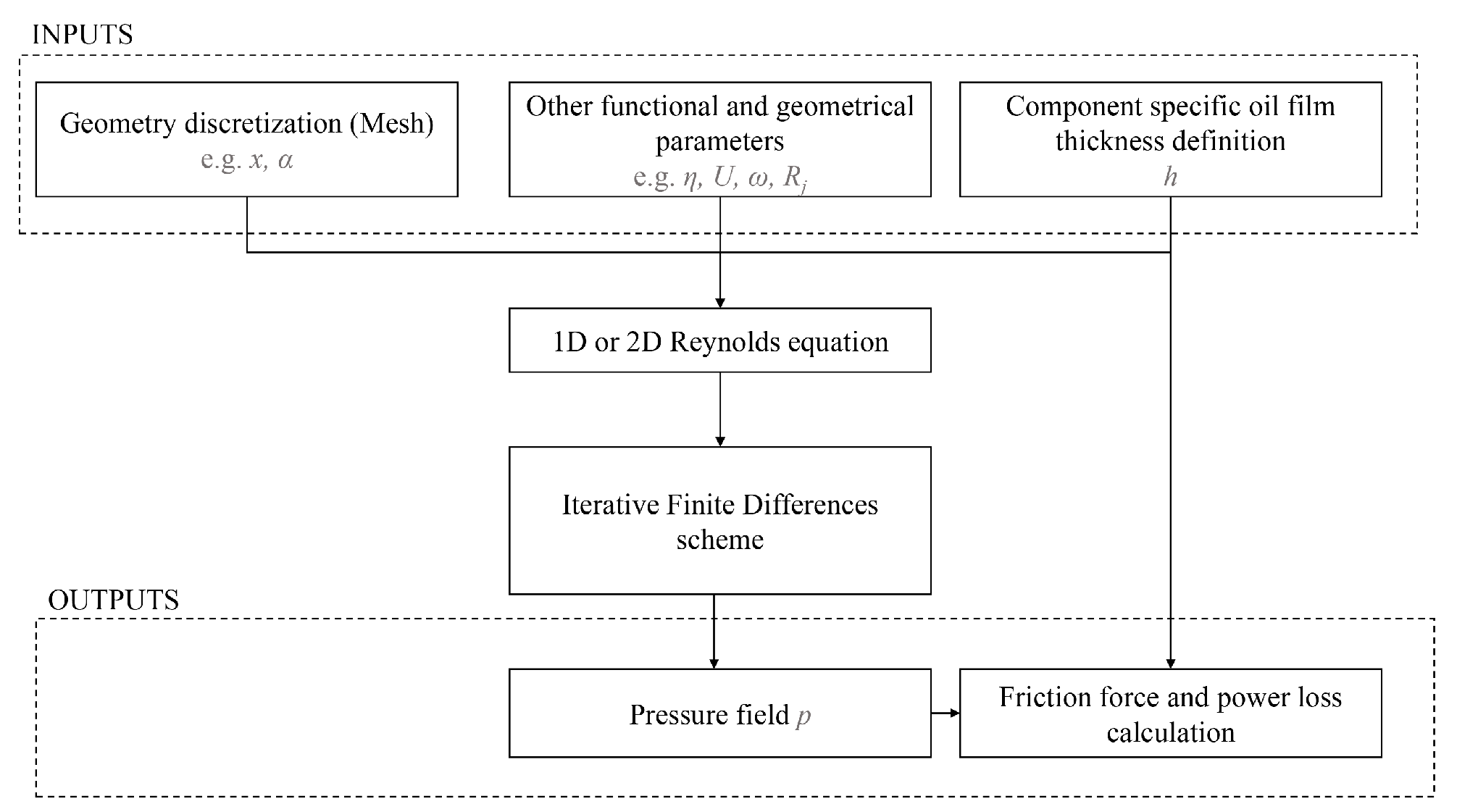
The general process of solution applied for each analyzed subsystem by the presented code is reported in Figure 5, in which x and represent axial and circumferential coordinates, respectively; is lubricant viscosity; U is piston instantaneous velocity; is angular crankshaft speed; is piston skirt radius; h is oil film thickness; and p is pressure. Starting from geometrical and tribological parameters, working conditions, and geometric discretization of the subsystem (one- or two-dimensional depending on the specific component), an initial guess of oil film thickness h can be used to numerically solve the Reynolds equation though a finite difference scheme (one or two-dimensional depending on the specific component) and obtain pressure field p inside the lubricant meatus. The calculation of the friction force and moment with inertial forces of the component allows to update oil film thickness distribution. Though an iterative process, the calculation can be completed in order to obtain correct oil film thickness h, pressure field p, friction force, friction moment, and power loss. Additional details are reported in the following sections for each engine component.
2.1.1. Piston Rings
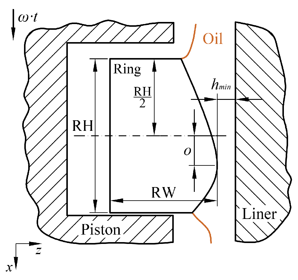
Piston rings exploit axial symmetry both geometrically and in terms of piston ring loads. In fact, the model depicted in Figure 6, the resulting discretization, and the Reynolds equation connected to them are one-dimensional:
where h represents oil film thickness, p is pressure, is oil viscosity, and U is instantaneous piston velocity (i.e., it was assumed the piston ring and piston had the same velocity).
In Figure 6, RH represents ring height, RW is ring width, o is ring face offset from the center of the ring, is angular crankshaft speed, and is minimal oil film thickness.
In order to solve Equation (1) by finite differences, it is necessary to hypothesize oil film thickness h. This was calculated through a purposely developed iterative scheme described in great detail in [31]. The calculation is also influenced by lubrication conditions (hydrodynamics, separation, cavitation) that change the configuration of meatus thickness h [31]. If minimal oil film thickness evaluated at each crankshaft angle is lower than the combined surface roughness, the lubrication regime is of the boundary condition type, and the lubricant meatus configuration changes; in this case, minimal oil film thickness was set to be equal to the combined surface roughness, and friction force and power loss can be directly computed with typical friction contact equations with friction coefficient [14].
2.1.2. Piston Skirt
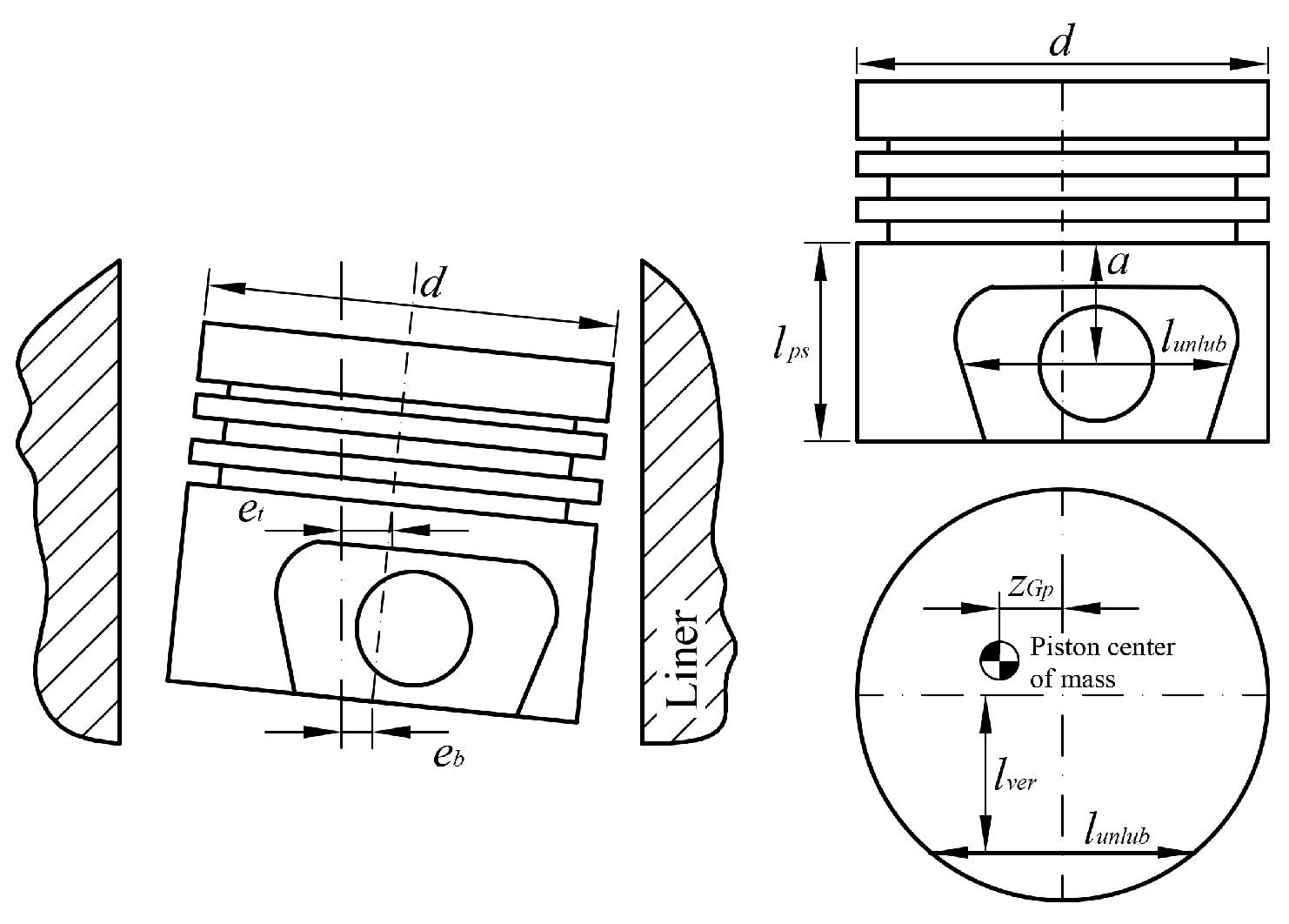
Axial symmetry of the geometry is not respected by the piston skirt, as the presence of the wrist pin implies nonsymmetric lubricated surfaces of the component. Therefore, hydrodynamic pressure acting on the piston skirt must be determined using the complete 2D Reynolds equation, which considers changes in oil film thickness in the axial (x) and circumferential () directions:
where is crankshaft angle, is crankshaft angular speed, and with reference to Figure 7, is piston skirt radius. The last term of Equation (2) represents the nonstationary contribution of the Reynolds equation on the condition that crankshaft angular speed is constant.
In this case, oil film thickness h is determined as a function of the eccentricity at top and bottom of the piston skirt, which are in turn related to the dynamic equilibrium of the piston itself. Additional parameters needed for the calculation are represented in Figure 7: a is the wrist pin vertical distance from the oil control ring, and are respectively the unlubricated area width and position with respect to the piston axis, is the piston skirt length and is the piston center of gravity position with respect to the piston axis.
Starting from arbitrary values of and , an initial guess of oil film thickness distribution is used to solve the 2D Reynolds equation applying the finite difference method [32] at each crank angle in order to estimate the pressure distribution, and evaluate piston friction force and moment. Together with piston inertial forces and moments, top and bottom eccentricities and are updated by applying an iterative technique until convergence, and oil film thickness h and pressure field p are evaluated, solving the complete Reynolds equation using the finite different method one last time.
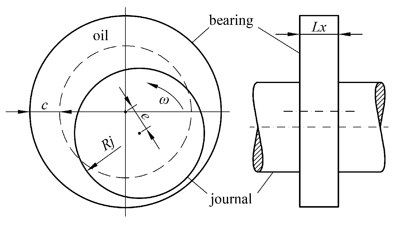
2.1.3. Connecting Rod and Main Bearings
The Reynolds equation related to the bearings is analogous to Equation (2), where represents the radius of the journal. In the case of journal bearings, oil film thickness h is related to eccentricity e and is in turn derived from the balance between hydrodynamic reaction and forces acting on the bearing. Considering Figure 8, e is eccentricity, is angular crankshaft speed, c is the mean radial gap of the bearing, is journal radius, and is bearing width. Here, Booker’s method [33,34] with Ocvirk short-bearing approximation is used to solve the equilibrium of forces and find e.
Booker’s method requires knowledge on the reaction force that the bearing supports. While this calculation is trivial for the connecting rod bearing, the situation is more complex when considering the main bearings. At each crank angle, the applied load acting on the connecting rod bearing can be considered as made up of a contribution from the force of the gas in the combustion chamber and one due to the inertia forces of the alternating and rotating masses. Three simplifications can be considered in order to obtain a quick estimate of the tribological performance of the connecting rod bearing. First, analysis is applicable to a single cylinder and can be considered to be an approximation of a multicylinder engine. Second, engine components are treated as rigid bodies, and they are not associated with elastic deformation. Lastly, the effect of engine fluctuations caused by the firing order and inertial imbalances can be limited to a few harmonics.
On the other hand, it is not as easy to evaluate loads acting on the main bearings. These are due in part to connecting rod bearing load reactions and in part to crankshaft unbalance forces (counterweights and connecting rod pins) [35]. This is an underdetermined problem because both crankshaft and crankcase have finite stiffness, and interactions between the connecting rod bearing load and the unbalanced crankshaft forces make the calculations complex. To avoid rather complex and expensive calculations, in this first version of the code, the so-called statically determinate method [36] was applied in which the crankshaft was assumed to have an articulation at each supporting bearing; therefore, the influence of forces acting beyond the two adjacent main bearings is neglected, and the crankshaft–basement system can be considered a succession of statically determinate systems.
3. Results
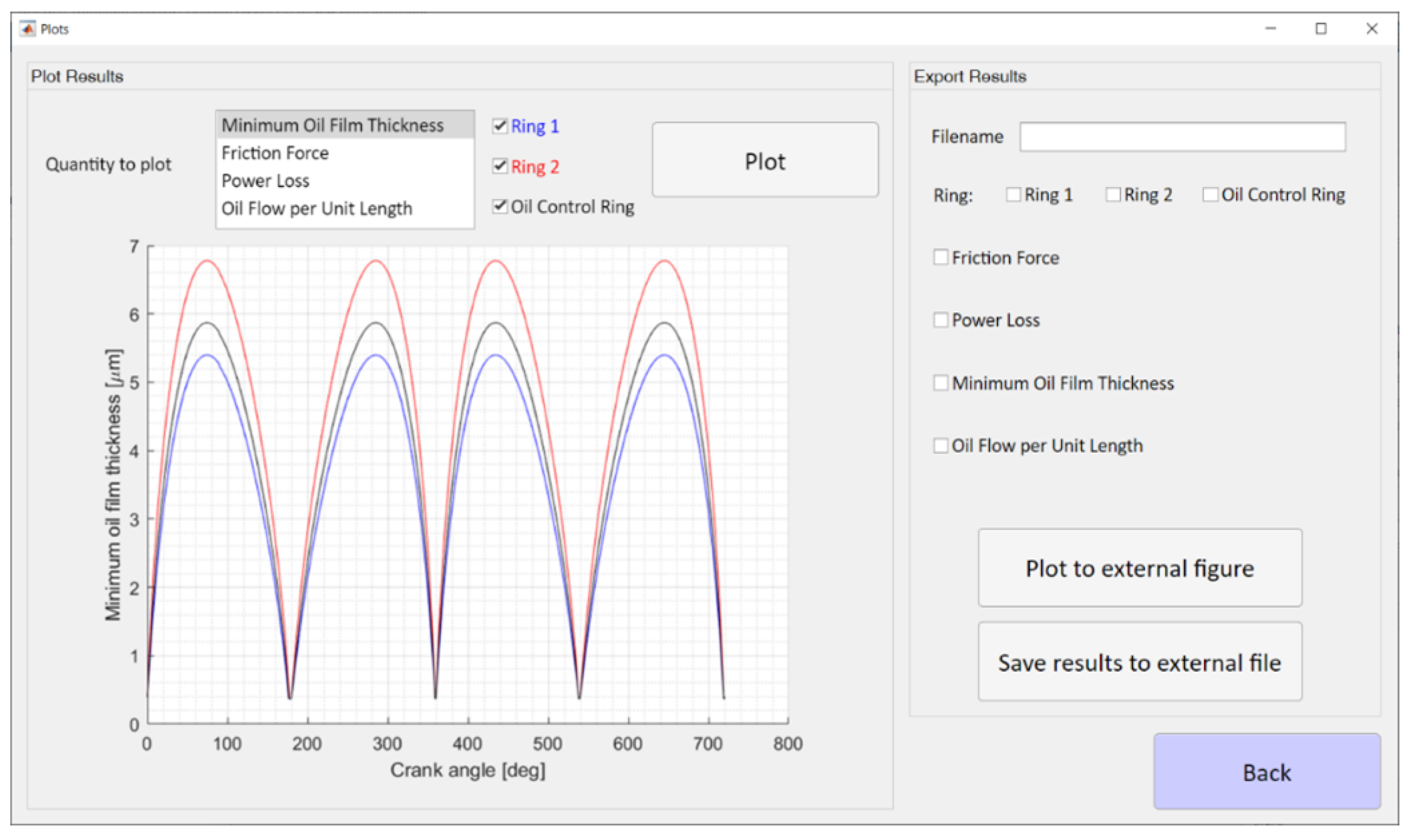
Results that can be accessed and exported by the user via the graphical interface (see Figure 9) include:
- quantities directly related to the Reynolds equation such as oil film thickness and pressure distribution;
- frictional forces due to viscous shear stresses and the associated power loss (typically obtained as the integral of the frictional force).
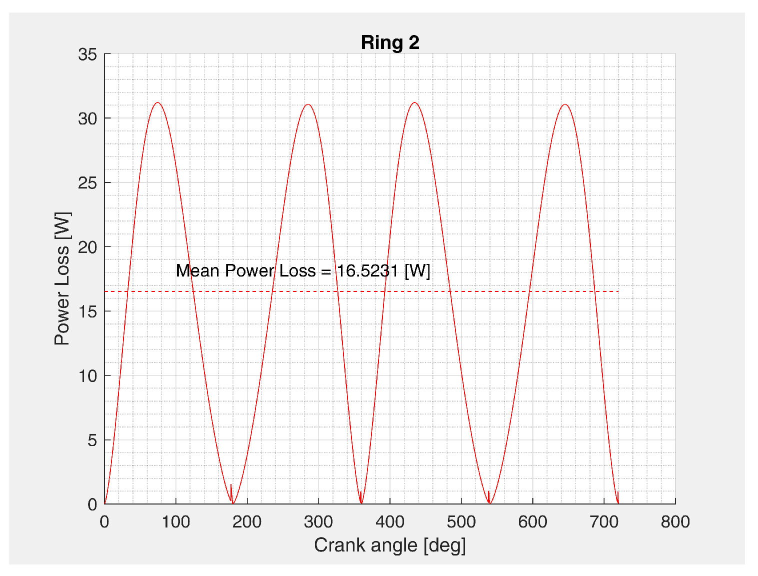
In detail, information on the instantaneous power loss, whose value changes as a function of the crankshaft rotation angle, can be condensed in its average value (see Figure 10). This value is in fact easily comparable with the experimentally obtained data.
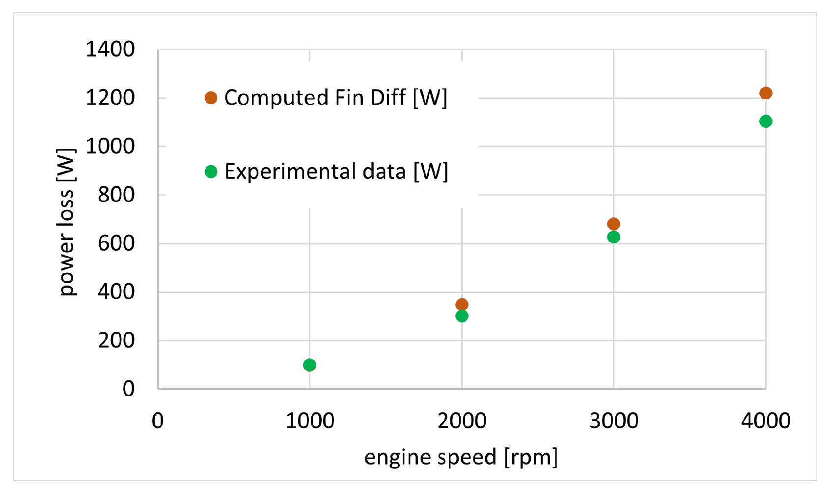
An experimental–numerical comparison was obtained for a four-cylinder medium-sized diesel engine in motored condition. The comparison was performed on four pistons, each with three piston rings and the related skirt. In addition, the connecting rod bearing contribution was accounted for. Experimental results were obtained from a stipdown test of the considered medium-sized diesel engine. Geometrical parameters and surface roughness values used in the numerical evaluation were obtained from direct measurement and the manufacturer’s technical drawing of the considered engine; further information on the geometrical parameters used in the simulation can be found in [26,37]. Lubricant viscosity was chosen at the estimated working temperature from the datasheet of the used lubricant during the experimental campaign; friction coefficient used in the code was estimated from the literature to be equal to [14].
Results in terms of average power are shown in Figure 11 for a speed range from 1000 to 4000 rpm. Maximal percentage deviation was 3.6% and was obtained at 4000 rpm.
A similar comparison was performed on the performance of the main bearings. Results are shown in Figure 12.
The experimental–numerical comparison shown above demonstrates the predictive capability of the code. However, to render this code useful in the preliminary design phase, it is necessary that it provides results that are compatible with industrial needs. For this reason, great attention was also paid to the time to result. Table 1 shows the calculation times required for each module contained within the code. A complete calculation on the piston assembly for four different speed values would therefore require less than 4 h, and about 5 h if the analysis also includes the main bearings.
Sensitivity Analysis of Piston Assembly Power Losses to Uncertain Parameters
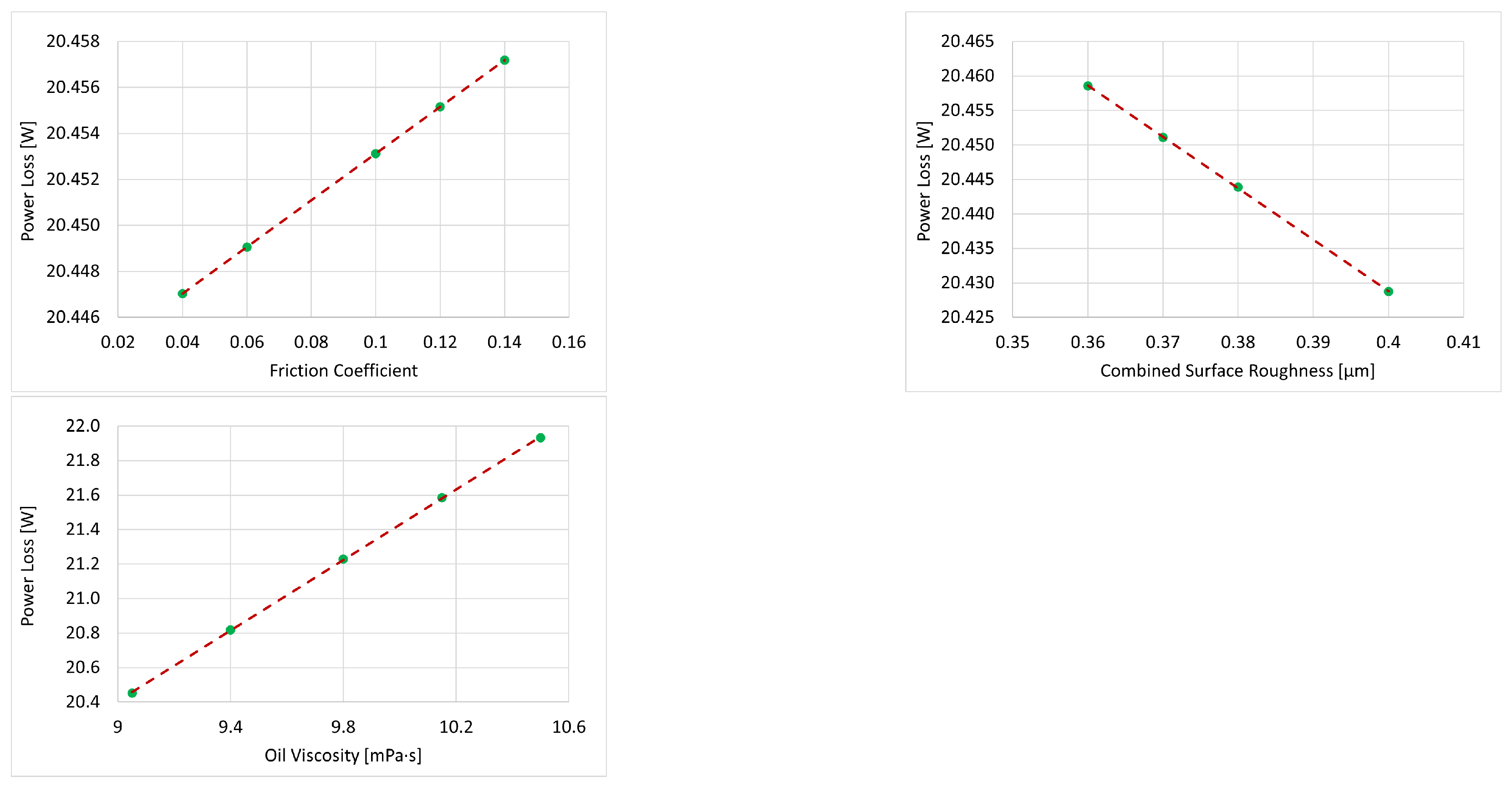
Some of the input parameters required by the numerical model developed for the estimation of friction losses, such as the friction coefficient, the combined surface roughness and the lubricating oil viscosity, are difficult to accurately assess. In particular, ranges of variability for these parameters are known from literature and sector industries, but their exact value is difficult to measure during the pre-design phases. For this reason, a sensitivity analysis of the friction losses of the piston unit as a function of the three uncertain parameters highlighted is carried out. In detail, a sensitivity analysis of the piston group components to the variation of a single parameter is firstly evaluated, in order to recognize correlation laws. In particular, the variability ranges of the three input parameters analyzed were chosen as follows: the friction coefficient varies between 0.04 and 0.14 [38,39], the combined surface roughness between and and the lubricating oil viscosity assumes values between and .
Analyzes were carried out keeping two of the three parameters constant, while varying the remaining one. In Figure 13 the effect of each parameter variation on the power loss of the first piston ring are shown. A linear correlation between the parameters and the component power loss can be highlighted. Considering the generic equation for a line, , in which m represents the slope and q is the y-coordinate of the point of intersection of the line with the y-axis, the slope of the line can be used as indication of the sensitivity of change in y dictated by a known change in x. Considering the linear correlations in Figure 13 between the power loss and the three parameters considered, the slopes , and of the line are used to indicate the sensitivity of the power loss to changes in the friction coefficient, combined surface roughness and oil viscosity, respectively.
More generally, this phenomenon was observed for all components of the piston group, whose slopes m of the line correlations are reported in Table 2: represents the sensitivity of the power loss to changes in the friction coefficient, is the sensitivity of the power loss to the combined surface roughness, and is the sensitivity of the power loss to changes of the oil viscosity.
The presented slopes were verified by simulating a different engine with comparable characteristics; numerical values depend on the particular geometric characteristics of the analyzed engine, but the relation between different coefficients remains unchanged. In particular, the friction coefficient had a greater effect on the oil control ring power losses (approximately 30% greater variation compared to the first piston ring for the same friction coefficient change) and the second piston ring was the least affected by this parameter.
The combined surface roughness effect was clearly higher for the connecting rod bearing (approximately one order of magnitude higher than the effect on the piston rings); moreover, in the analyzed range of variability of the combined surface roughness, a decrease in parameters leads to an increase in power losses. However, the uncertainty of the roughness was within the range of tenths of a micrometer, resulting in variability in lost power of a few watts at most.
Lubricating oil viscosity presented a greater effect on the piston skirt (approximately 3 times greater than the effect on the connecting rod bearing). The same relationship was maintained between piston rings, in which the oil control ring was the most affected by the parameter variation, followed by the first ring and then by the second.
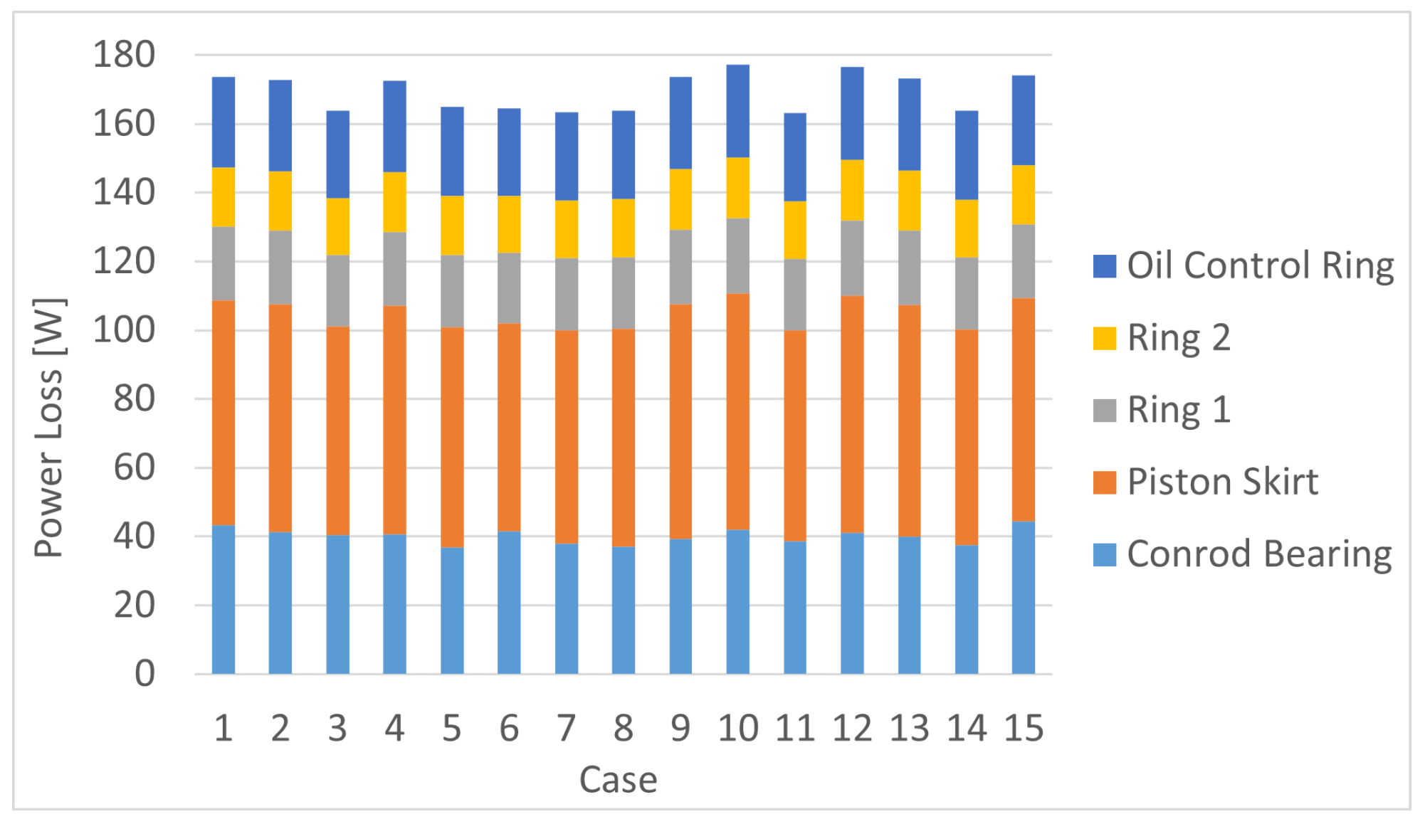
In order to evaluate the uncertainty of these parameters on the piston group power losses, the Latin hypercube sampling method [40] was used employing 15 distinct cases. The variation domain of each parameter was divided into a number of ranges equal to the number of analyzed cases. In each of these, a random calculation point was selected. This generated the 15 cases reported in Table 3 that were subsequently analyzed.
The power loss results obtained for each analyzed case are illustrated in Figure 14, divided by component contribution. The greater effect of power loss variability was due to the effect of the connecting rod bearing and the piston skirt, while the piston ring effect was more contained.
To evaluate the piston group power loss uncertainty, the maximal distribution range was used, calculated as the maximal value minus the minimal value of the total power loss of the group, brought in the percentage to the average value of lost power. An uncertainty on lost power of plus or was therefore calculated. This value shows that the choice of the uncertain parameters within the available ranges in literature and typically used by manufacturers leads to limited variability in piston group power loss, supporting the robustness of the model developed in the initial design phases of internal combustion engines, where exact values of considered parameters are not yet available.
4. Conclusions
We presented a code for the estimation of friction losses in the piston group and main bearings. The code could serve as a valuable preliminary design tool due to the following features:
- use of the smallest possible number of inputs to calibrate the models, a necessary feature in the preliminary phase when not all design details are already available;
- use of semianalytical models with simple discretizations that guarantee low computational times;
- ease of use thanks to a graphical interface for data entry, and for the interpretation and export of results;
- proven predictive capabilities thanks to the experimental numerical comparison operated in different operating conditions;
- robustness of the model in the choice of uncertain parameters during the initial design phases of internal combustion engines, which guarantees limited variability in estimated power losses.
Author Contributions
Conceptualization, C.D., C.G. and L.G.; methodology, C.D., C.G. and L.G.; software, C.G. and L.G.; investigation, C.G. and L.G.; writing—original draft preparation, C.G. and L.G.; writing—review and editing, C.D.; visualization, L.G.; supervision, C.D. and C.G. All authors have read and agreed to the published version of the manuscript.
Funding
This research received no external funding.
Institutional Review Board Statement
Not applicable.
Informed Consent Statement
Not applicable.
Data Availability Statement
Not applicable.
Conflicts of Interest
The authors declare no conflict of interest.
References
- Rahnejat, H. Tribology and Dynamics of Engine and Powertrain: Fundamentals, Applications and Future Trends; Woodhead: Cambridge, UK, 2010. [Google Scholar]
- Delprete, C.; Razavykia, A. Piston dynamics, lubrication and tribological performance evaluation: A review. Int. J. Engine Res. 2018, 21, 725–741. [Google Scholar] [CrossRef]
- Taylor, C.M. Engine Tribology; Elsevier Science & Techn.: Amsterdam, The Netherlands, 1993. [Google Scholar]
- Heywood, J. Internal Combustion Engine Fundamentals; McGraw-Hill: New York, NY, USA, 1988. [Google Scholar]
- Miltsios, G.K.; Patterson, D.J.; Papanastasiou, T.C. Solution of the Lubrication Problem and Calculation of the Friction Force on the Piston Rings. J. Tribol. 1989, 111, 635–641. [Google Scholar] [CrossRef]
- Ma, M.T.; Smith, E.H.; Sherrington, I. A Three-Dimensional Analysis of Piston Ring Lubrication Part 1: Modelling. Proc. Inst. Mech. Eng. Part J. Eng. Tribol. 1995, 209, 1–14. [Google Scholar] [CrossRef]
- Ma, M.T.; Smith, E.H.; Sherrington, I. A Three-Dimensional Analysis of Piston Ring Lubrication Part 2: Sensitivity Analysis. Proc. Inst. Mech. Eng. Part J. Eng. Tribol. 1995, 209, 15–27. [Google Scholar] [CrossRef]
- Priest, M.; Dowson, D.; Taylor, C. Predictive wear modelling of lubricated piston rings in a diesel engine. Wear 1999, 231, 89–101. [Google Scholar] [CrossRef]
- Rodríguez, A.L.; Vølund, A.; Klit, P. Modeling of piston ring wear. Proc. Inst. Mech. Eng. Part J. Eng. Tribol. 2020, 235, 629–638. [Google Scholar] [CrossRef]
- Stanley, R.; Taraza, D.; Henein, N.; Bryzik, W. A Simplified Friction Model of the Piston Ring Assembly; SAE Technical Paper Series; SAE International: Warrendale, PA, USA, 1999. [Google Scholar] [CrossRef]
- Morris, N.; Rahmani, R.; Rahnejat, H.; King, P.; Fitzsimons, B. The influence of piston ring geometry and topography on friction. Proc. Inst. Mech. Eng. Part J. Eng. Tribol. 2012, 227, 141–153. [Google Scholar] [CrossRef] [Green Version]
- Piao, Y.; Gulwadi, S.D. Numerical Investigation of the Effects of Axial Cylinder Bore Profiles on Piston Ring Radial Dynamics. J. Eng. Gas Turbines Power 2003, 125, 1081–1089. [Google Scholar] [CrossRef]
- Zavos, A. Effect of Coating and Low Viscosity Oils on Piston Ring Friction under Mixed Regime of Lubrication through Analytical Modelling. Lubricants 2021, 9, 124. [Google Scholar] [CrossRef]
- Jeng, Y.R. Theoretical Analysis of Piston-Ring Lubrication Part I—Fully Flooded Lubrication. Tribol. Trans. 1992, 35, 696–706. [Google Scholar] [CrossRef]
- Jeng, Y.R. Theoretical Analysis of Piston-Ring Lubrication Part II—Starved Lubrication and Its Application to a Complete Ring Pack. Tribol. Trans. 1992, 35, 707–714. [Google Scholar] [CrossRef]
- Bedajangam, S.K.; Jadhav, N.P. Friction Losses between Piston Ring-Liner Assembly ofInternal Combustion Engine: A Review. Int. J. Sci. Res. Publ. 2013, 3, 1–3. Available online: http://www.ijsrp.org/research-paper-0613.php?rp=P181298 (accessed on 29 March 2022).
- Oh, K.P.; Li, C.H.; Goenka, P.K. Elastohydrodynamic Lubrication of Piston Skirts. J. Tribol. 1987, 109, 356–362. [Google Scholar] [CrossRef]
- Smirnov, S.V.; Vorobyev, A.A. Hydrodynamic lubrication of a two-piece piston skirt considering deformations. In Proceedings of the III International Conference on Advanced Technologies in Materials Science, Mechanical and Automation Engineering, Krasnoyarsk, Russian, 29–30 April 2021; AIP Publishing: Melville, NY, USA, 2021. [Google Scholar] [CrossRef]
- Li, D.F.; Rohde, S.M.; Ezzat, H.A. An Automotive Piston Lubrication Model. ASLE Trans. 1983, 26, 151–160. [Google Scholar] [CrossRef]
- Liu, K.; Xie, Y.B.; Gui, C.L. A comprehensive study of the friction and dynamic motion of the piston assembly. Proc. Inst. Mech. Eng. Part J. Eng. Tribol. 1998, 212, 221–226. [Google Scholar] [CrossRef]
- Forero, J.D.; Ochoa, G.V.; Alvarado, W.P. Study of the Piston Secondary Movement on the Tribological Performance of a Single Cylinder Low-Displacement Diesel Engine. Lubricants 2020, 8, 97. [Google Scholar] [CrossRef]
- Ciulli, E. A Review of Internal Combustion Engine Losses Part 1: Specific Studies on the Motion of Pistons, Valves and Bearings. Proc. Inst. Mech. Eng. Part J. Automob. Eng. 1992, 206, 223–236. [Google Scholar] [CrossRef]
- Thring, R.H. Engine Friction Modeling; SAE Technical Paper Series; SAE International: Warrendale, PA, USA, 1992. [Google Scholar] [CrossRef]
- Allmaier, H.; Priestner, C.; Six, C.; Priebsch, H.; Forstner, C.; Novotny-Farkas, F. Predicting friction reliably and accurately in journal bearings—A systematic validation of simulation results with experimental measurements. Tribol. Int. 2011, 44, 1151–1160. [Google Scholar] [CrossRef]
- Allmaier, H.; Priestner, C.; Reich, F.; Priebsch, H.; Forstner, C.; Novotny-Farkas, F. Predicting friction reliably and accurately in journal bearings – The importance of extensive oil-models. Tribol. Int. 2012, 48, 93–101. [Google Scholar] [CrossRef]
- Razavykia, A.; Delprete, C.; Baldissera, P. Numerical Study of Power Loss and Lubrication of Connecting Rod Big-End. Lubricants 2019, 7, 47. [Google Scholar] [CrossRef] [Green Version]
- Santos, N.D.S.A.; Roso, V.R.; Faria, M.T.C. Review of engine journal bearing tribology in start-stop applications. Eng. Fail. Anal. 2020, 108, 104344. [Google Scholar] [CrossRef]
- Sfyris, D.; Chasalevris, A. An exact analytical solution of the Reynolds equation for the finite journal bearing lubrication. Tribol. Int. 2012, 55, 46–58. [Google Scholar] [CrossRef]
- Chasalevris, A.; Sfyris, D. Evaluation of the finite journal bearing characteristics, using the exact analytical solution of the Reynolds equation. Tribol. Int. 2013, 57, 216–234. [Google Scholar] [CrossRef]
- Lozano, W.O.; Fonseca-Vigoya, M.D.S.; Pabón-León, J. Study of the Kinematics and Dynamics of the Ring Pack of a Diesel Engine by Means of the Construction of CFD Model in Conjunction with Mathematical Models. Lubricants 2021, 9, 116. [Google Scholar] [CrossRef]
- Delprete, C.; Razavykia, A. Modeling of Oil Film Thickness in Piston Ring/Liner Interface. Int. J. Mech. Eng. Robot. Res. 2017, 210–214. [Google Scholar] [CrossRef] [Green Version]
- Singhal, G. Computation methods for hydrodynamic problems (Reynold’s equation). Comput.-Aided Des. 1981, 13, 151–154. [Google Scholar] [CrossRef]
- Booker, J.F. Dynamically Loaded Journal Bearings: Mobility Method of Solution. J. Basic Eng. 1965, 87, 537–546. [Google Scholar] [CrossRef]
- Booker, J.F. Dynamically-Loaded Journal Bearings: Numerical Application of the Mobility Method. J. Lubr. Technol. 1971, 93, 168–174. [Google Scholar] [CrossRef]
- Myung-Rae, C.; Dae-Yoon, O.; Seung-Hyuk, R.; Dong-Chul, H. Load characteristics of engine main bearing: Comparison between theory and experiment. KSME Int. J. 2002, 16, 1095–1101. [Google Scholar] [CrossRef]
- Von Schnurbein, E. A New Method of Calculating Plain Bearings of Statically Indeterminate Crankshafts; SAE Technical Paper Series; SAE International: Warrendale, PA, USA, 1970. [Google Scholar] [CrossRef]
- Delprete, C.; Razavykia, A.; Baldissera, P. Detailed analysis of piston secondary motion and tribological performance. Int. J. Engine Res. 2020, 21, 1647–1661. [Google Scholar] [CrossRef]
- Chaudhari, T.; Sutaria, B. Investigation of friction characteristics in segmented piston ring liner assembly of IC engine. Perspect. Sci. 2016, 8, 599–602. [Google Scholar] [CrossRef] [Green Version]
- Westerfield, Z.; Liu, Y.; Kim, D.; Tian, T. A Study of the Friction of Oil Control Rings Using the Floating Liner Engine. SAE Int. J. Engines 2016, 9, 1807–1824. [Google Scholar] [CrossRef]
- McKay, M.D.; Beckman, R.J.; Conover, W.J. A Comparison of Three Methods for Selecting Values of Input Variables in the Analysis of Output from a Computer Code. Technometrics 1979, 21, 239–245. [Google Scholar] [CrossRef]
Figure 1.
Main menu of proposed tool.

Figure 2.
Input tab for crank geometry and inertial data used for current analysis.

Figure 3.
Program setup flowchart for evaluating friction losses due to piston rings.

Figure 4.
Diagram representing constituent code elements.

Figure 5.
Flowchart of general process of the model solution individually applied to each subsystem (piston rings, piston skirt, journal bearings) analyzed.
Figure 5.
Flowchart of general process of the model solution individually applied to each subsystem (piston rings, piston skirt, journal bearings) analyzed.

Figure 6.
Representative diagram of fundamental piston ring sector.

Figure 7.
Eccentricity and fundamental geometric quantities of piston skirt model.

Figure 8.
Representative diagram of semianalytical journal bearing model.

Figure 9.
Example of result output tab for the relative module to piston rings.

Figure 10.
Example of results on instantaneous power loss and its average value for the second piston ring.
Figure 10.
Example of results on instantaneous power loss and its average value for the second piston ring.

Figure 11.
Experimental–numerical comparison for piston assembly (piston rings, skirt, and connecting rod bearing) for four different speed values.
Figure 11.
Experimental–numerical comparison for piston assembly (piston rings, skirt, and connecting rod bearing) for four different speed values.

Figure 12.
Experimental–numerical comparison for five main bearings supporting crankshaft for four different speed values.
Figure 12.
Experimental–numerical comparison for five main bearings supporting crankshaft for four different speed values.

Figure 13.
Example of the uncertain parameters effect on the power losses of the first piston ring.

Figure 14.
Piston assembly power losses for 15 analyzed cases using Latin hypercube sampling method.
Figure 14.
Piston assembly power losses for 15 analyzed cases using Latin hypercube sampling method.


Table 1.
Computation times required by each module for a single value of rotational speed.
| Module | Calculation Time [min] |
|---|---|
| Piston Rings | 8 |
| Piston Skirt | 40 |
| Journal Bearing | 10 |
Table 2.
Sensitivity of piston assembly components power losses to uncertain parameters.
| Component | [W] | [W μm] | [W mPa s] |
|---|---|---|---|
| Ring 1 | 0.102 | 0.74 | 1.022 |
| Ring 2 | 0.065 | −0.397 | 0.857 |
| Oil control ring | 0.132 | −0.782 | 1.277 |
| Conrod bearing | − | −10.614 | 1.791 |
| Piston skirt | − | − | 6.625 |
Table 3.
Cases selected by Latin hypercube sampling method.
| Case | Oil Viscosity [mPa s] | Surface Rough. μm | Friction Coeff. [−] |
|---|---|---|---|
| 1 | 9.873 | 0.363 | 0.104 |
| 2 | 9.974 | 0.373 | 0.045 |
| 3 | 9.181 | 0.393 | 0.075 |
| 4 | 10.045 | 0.388 | 0.054 |
| 5 | 9.654 | 0.398 | 0.061 |
| 6 | 9.120 | 0.376 | 0.122 |
| 7 | 9.371 | 0.361 | 0.095 |
| 8 | 9.567 | 0.392 | 0.079 |
| 9 | 10.291 | 0.397 | 0.127 |
| 10 | 10.392 | 0.381 | 0.047 |
| 11 | 9.292 | 0.384 | 0.092 |
| 12 | 10.407 | 0.388 | 0.084 |
| 13 | 10.177 | 0.369 | 0.108 |
| 14 | 9.477 | 0.375 | 0.116 |
| 15 | 9.802 | 0.366 | 0.067 |
Publisher’s Note: MDPI stays neutral with regard to jurisdictional claims in published maps and institutional affiliations. |
© 2022 by the authors. Licensee MDPI, Basel, Switzerland. This article is an open access article distributed under the terms and conditions of the Creative Commons Attribution (CC BY) license (https://creativecommons.org/licenses/by/4.0/).
Share and Cite
MDPI and ACS Style
Delprete, C.; Gastaldi, C.; Giorio, L. A Minimal Input Engine Friction Model for Power Loss Prediction. Lubricants 2022, 10, 94. https://0-doi-org.brum.beds.ac.uk/10.3390/lubricants10050094
AMA Style
Delprete C, Gastaldi C, Giorio L. A Minimal Input Engine Friction Model for Power Loss Prediction. Lubricants. 2022; 10(5):94. https://0-doi-org.brum.beds.ac.uk/10.3390/lubricants10050094
Chicago/Turabian StyleDelprete, Cristiana, Chiara Gastaldi, and Lorenzo Giorio. 2022. "A Minimal Input Engine Friction Model for Power Loss Prediction" Lubricants 10, no. 5: 94. https://0-doi-org.brum.beds.ac.uk/10.3390/lubricants10050094
Note that from the first issue of 2016, this journal uses article numbers instead of page numbers. See further details here.