Article

Exergy, Economic, and Life-Cycle Assessment of ORC System for Waste Heat Recovery in a Natural Gas Internal Combustion Engine

by
Guillermo Valencia Ochoa
1,*,
Javier Cárdenas Gutierrez
2 and
Jorge Duarte Forero
1
1
Programa de Ingeniería Mecánica, Universidad del Atlántico, Carrera 30 Número 8-49, Puerto Colombia, Barranquilla 080007, Colombia
2
Facultad de Ingeniería, Universidad Francisco de Paula Santander, Avenida Gran Colombia No. 12E-96, Cúcuta 540003, Colombia
*
Author to whom correspondence should be addressed.
Submission received: 10 November 2019 / Revised: 23 December 2019 / Accepted: 24 December 2019 / Published: 1 January 2020

Abstract

:
In this article, an organic Rankine cycle (ORC) was integrated into a 2-MW natural gas engine to evaluate the possibility of generating electricity by recovering the engine’s exhaust heat. The operational and design variables with the greatest influence on the energy, economic, and environmental performance of the system were analyzed. Likewise, the components with greater exergy destruction were identified through the variety of different operating parameters. From the parametric results, it was found that the evaporation pressure has the greatest influence on the destruction of exergy. The highest fraction of exergy was obtained for the Shell and tube heat exchanger (ITC1) with 38% of the total exergy destruction of the system. It was also determined that the high value of the heat transfer area increases its acquisition costs and the levelized cost of energy (LCOE) of the thermal system. Therefore, these systems must have a turbine technology with an efficiency not exceeding 90% because, from this value, the LCOE of the system surpasses the LCOE of a gas turbine. Lastly, a life cycle analysis (LCA) was developed on the system operating under the selected organic working fluids. It was found that the component with the greatest environmental impact was the turbine, which reached a maximum value of 3013.65 Pts when the material was aluminum. Acetone was used as the organic working fluid.

1. Introduction

Due to the large consumption of coal, oil, natural gas, and other fossil fuels, energy production is increasingly unusual. Therefore, clean and efficient substitutes are needed to protect the environment and support sustainable development. Thus, with the increase in population and the global industry, energy-saving and emission reduction have been considered the main objective of the energy development strategy [1]. The sustainability goal as well as the environmental and energy analysis had been conducted by some researchers in waste heat recovery systems based on ORC to convert the energy from renewable sources such as biofuels, biomass, solar energy, and geothermal values to electric energy [2]. One way to improve energy efficiency and potentially reduce pollution is by applying ORC technology as waste heat recovery devices [3,4]. Organic Rankine cycles (ORC) are an effective way of converting medium-low temperature heat into electricity that cannot be used for conventional high-temperature Rankine cycles, even though many studies have been conducted in recent decades. The use of ORC as an alternative to waste heat recovery has received relatively little industrial attention [5,6,7,8,9].
In recent years, research has been conducted to improve ORC performance based on the selection of different organic working fluids. Vivian et al. [10] considered the selection of the most suitable working fluid and cycle configuration for a heat source to find the optimal ORC design. Therefore, they performed a design optimization of four different ORC configurations operating with 27 organic working fluids in the temperature heat source ranging from 120 °C to 180 °C, where the results showed that fluid temperature and heat source inlet temperature plays an important role in predicting the optimum performance of all system configurations. Yu et al. [11] proposed a new predictive method for simultaneously determining the working fluid and operating conditions in an ORC system, concluding that the waste heat can be fully recovered, and a maximum output power is obtained when there is a positive temperature difference between the waste heat inlet temperature and the critical working fluid temperature. However, these studies do not consider, in their scope, the environmental impact’s assessment to have a sustainable solution that can be implemented worldwide in the industrial sector.
On the other hand, Invernizzi et al. [12] investigated the possible substitution of HFC-134a in ORC applications by two low GWP cooling fluids such as HFO-1234yf and HFO-1234ze, adopting the Peng Robinson model available in Aspen Plus v7.3. The results showed a net power decrease of 13% and 1% for HFO-1234yf and HFO-1234ze, respectively. A decrease in turbine power of 20% was also obtained when operating with HFO-1234yf and 28% when operating with HFO-1234ze. Mavrou et al. [13] studied the performance of various working fluid mixtures in the ORC with heat storage using FPC (flat plate collectors). For this, they developed a multi-criteria analysis, which revealed important tradeoffs between various system parameters such as the thermal efficiency of the ORC, the net power generated, the volume ratio across the turbine, the mass flow of the working fluid, the evaporator temperature, the temperature in the storage tank, and the total annual operating life of the ORC. Among the limitations of these works are that the studies were not performed for a characterized thermal source that would guarantee the results under real operational conditions. They consider fluids that do not comply with international standards of safety, thermal stability, and environmental criteria [14].
Karellas and Braimakis [15] developed a thermodynamic modeling and thermo-economic analysis of a micro-scale trigeneration system capable of combining heat and energy production and cooling based on the combined operation between an ORC and a Steam Compression Cycle. Only the effect of condensation and evaporation temperatures on system performance was evaluated. The results show an exergetic efficiency of the ORC of around 7%. Savings in fuel and electricity consumption represented an internal rate of return (IRR) of approximately 12% with a payback period of seven years. Despite being a very potential configuration, the results are very limited in scope since the environmental impacts have not been evaluated.
Another important parameter to consider in the design of the ORC is the Pinch Point and depends largely on the conditions of the source, sump, and selected working fluids [16]. Wang et al. [17] studied the selection of some organic working fluids to evaluate the correspondence between the evaporator Pinch Point and the condenser Pinch Point on the thermo-economic performance of the ORC system. The results show that the optimum working fluid among those present is R11, and the relationship between the evaporator pinch point and the most suitable condenser is 1.25–1.5. Other authors have carried out the analysis and optimization of new ORC systems by integrating them to other energetic processes.
Many of the studies also focus on improving the exergetic and/or exergo-economic performance of the ORC system [3]. Mahmoudi and Ghavimi [18] conducted a thermo-economic analysis of an integrated carbon dioxide and the ORC energy system using liquefied natural gas as a heat sink. For the proposed system, the authors performed multi-objective optimization using a genetic algorithm and selecting the unit cost of the product as objective functions and the exergetic efficiency. The results showed that the highest and second-highest exergy destruction rates occur in a catalytic burner and fuel cell. Zhang et al. [19] presented a new energy cycle for cascading the ORC of an offshore gas turbine. As for performance indicators, they considered net energy production and leveled energy cost. The results showed that the proposed waste heat recovery system could increase net energy production by 30.1% compared to the gas turbine alone.
To evaluate the impact on the environment with the use of ORC technology, different environmental methodologies, and indicators have been used [2,20], which have been defined within the object of study in various analyses through a Life Cycle Analysis (LCA). Cioccolanti et al. [21] investigated a plant with combined cooling, heating, and energy systems, which includes an ORC plant. The authors performed a sensitivity analysis of the environmental and energy impact of the plant by varying the organic fluid in the ORC unit. Their results confirmed that the LCA was of paramount importance for appropriate selections of component specifications and operating conditions of the integrated system. Ding et al. [22] established an environmental model of the ORC system and determined that fabrication and working fluid leakage are important for an LCA. Therefore, the environmental impact of working fluids for the ORC cannot be neglected. Heberle et al. [23] performed a Life Cycle Analysis (LCA) for geothermal power generation in binary power plants with ORC facilities, based on scenarios with representative conditions from Germany, to evaluate potential plant concepts considering fluid work losses and the associated environmental impact. This study found that substituting working fluids such as R245fa and R134a with low Global Warming Potentials (GWP) fluids such as R1233zd and R1234yf leads to 2% higher exergetic efficiency and an 83% reduction of global warming impact.
Several relevant works have been oriented for the development of theoretical models of waste heat recovery systems with organic Rankine cycles [24,25,26]. In this order of ideas, research into new configurations of the organic Rankine cycle to recover residual heat in the exhaust gases in an internal combustion engine, is benefited by these. Shi et al. [27] used the traditional design method, which does not adequately adapt to internal combustion engine waste heat recovery because of the specific large-gradient temperature drop characteristic of the residual heat in combustion engines. This led to a large number of investigations to implement this system optimally. Therefore, the research covered a review of the various models proposed to determine the cycle with the ideal modifications. However, its integration with industrial natural gas generation engines has not been widely evaluated [28]. The implementation of these generation solutions from waste gases, in addition to minimizing the environmental impacts in each of the phases of the life cycle of these processes, pursue the sustainability of these systems [22,29].
The sustainability of waste heat recovery systems based on ORC can be promoted through the integration of the energy method and environmental impact assessment through life cycle analysis [2]. Thus, it is concluded that the sustainability of waste heat recovery systems using ORC is more favorable than generation systems using petroleum-based fuels for their operation [2].
The environmental impacts of a heat recovery system change when using different working fluids and materials in its components [
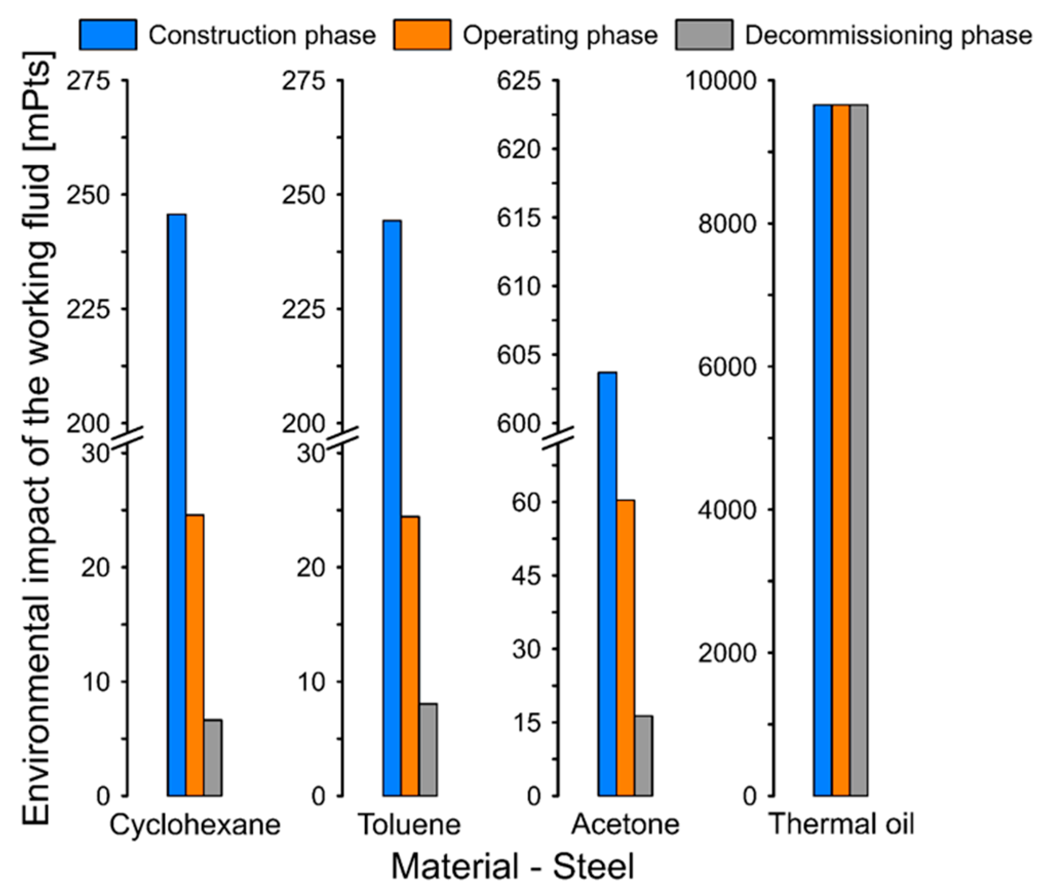
30]. Therefore, a life cycle analysis was developed in detail to evaluate the environmental impacts of an organic Rankine cycle, where the main objective was to evaluate seven different organic fluids in both the construction phase, operation, and decommissioning. It is concluded that the greatest potential impacts in the global warming category occur in the construction phase [20].
Among the benefits of proposing sustainable waste heat recovery systems is that they demand less consumption of resources for energy production [31]. They make it possible to achieve a sustainable energy supply by adopting environmentally-friendly organic fluids, in terms of low ozone depletion potential and global warming potential [30,32]. This allows the amount of reusable material to be increased at the end of the product life cycle, which significantly reduces environmental impacts throughout the life of the thermal system [33].
Additionally, this approach also complements the identification of exergetic improvement opportunities that can be determined with dissipative energy balances, as exergy studies have been conducted for this purpose [4,34]. However, the results obtained by complementing the environmental analysis with the exergy analysis for the processes of energy recovery in the exhaust gases through ORC, allow proposing sustainable energy solutions that favor their application and inclusion in the industrial market.
Despite many studies on performance improvements for different ORC configurations through the selection of working fluids, optimization of operating parameters and equipment characteristics, and environmental impact assessment, very little information is available in the literature on multi-objective optimizations involving thermal, economic, and environmental criteria. In most cases, no systematic approach is offered that correlates these different variables for the different ORC applications. The objective and scientific novelty of this study is to propose an exergetic, economic, and environmental evaluation through indicators such as net power, exergy destroyed by components, LCOE, and the environmental impacts of a residual heat recovery system using ORC in an industrial power generation engine to natural gas, by changing operational parameters such as turbine efficiency, evaporation pressure, evaporator, and condenser pinch point. This study provides guidelines and recommendations for exergetic, economic, and environmental improvement for the configuration of the heat recovery system based on ORC to design generation systems for cleaner production of electricity with lower environmental impacts.

2. Methodology

2.1. System Description

The engine is coupled with an organic Rankine cycle (ORC) configuration as a waste heat recovery system of the engine exhaust gases with the main objective to generate additional energy without consuming extra natural gas in the generating engine. The plant under study corresponds to a Jenbacher JMS 612 GS-N engine, which has been widely used for self-generation of energy in various industries. In this study, the engine is installed in a plastic sector plant in the city of Barranquilla—Colombia, with an effective efficiency of 38.58%.
The thermo-economic and environmental impact assessment of the waste heat recovery system based on ORC for the generation engine requires the evaluation and characterization of the thermal energy available in the exhaust gases. Therefore, a dynamic engine model of the engine whose characteristic parameters can be observed in Table 1 was developed in detail as a function of the mean value measured [35].
In this application, as shown in Figure 1, the gas engine is regularly generating a variable energy demand as the industrial process requires. Thus, the engine regulates the flow through valves (states 5 and 6) to obtain the desired natural gas volumetric flow that enters the engine cylinders and allows it to have an operating range between 1000 kW and 1982 kW. At a nominal operation condition, the engine generates exhaust gases (state 8) with an outlet temperature in the range of 580 °C to 650 °C, to reach the turbocharger turbines, where they are expanded and residual gases are obtained (state 10), which are used by the ORC as a thermal energy source.
Once at this point (state 10), the exhaust gases are used in a tube and shell heat exchanger (ITC1) to heat the thermal oil that serves as the heat source for the ORC. The geometrical configuration of the ITC1 is shown in Figure 2. This equipment can be constructed of multiple and flexible geometrical configurations in addition to the different arrangements that can be obtained. This versatility places it in a privileged position compared to other types of devices increasing their demand and applicability [37].
Both the evaporator (ITC 2) and condenser (ITC3) are flat plate heat exchangers. The geometrical configuration of this is shown in Figure 3. This exchanger is used for applications with restrictions on the weight and volume of the elements. Thus, the distance between plates is one of the most influential variables in the design of the parallel plate heat exchanger (ITC2, ITC3) on the ORC system side [3]. For the power ranges obtained in this system, a centrifugal pump (P1 and P2) and a turbine that was a radial-inflow turbine were considered.
The hot thermal oil (current 1AT) serves as a thermal source to evaporate in the (ITC 2) organic fluid to superheated steam (1 ORC) at the highest pressure and temperature of the ORC, where it enters the turbine (T1). As the organic fluid in the turbine (T1) from the evaporator (ITC 2) expands, an energy conversion process occurs in the generated electricity. The expansion of the fluid is given until the lowest pressure to enter the condenser (ITC 3), where all the mass is condensed (current 3 ORC). Next, in the pump (B2), the fluid is taken to the evaporating pressure in the ITC 2 exchanger, which completes the ORC cycle [4].

2.2. Thermodynamic Analysis

To perform the thermodynamic analysis of the system, some considerations were taken into account, such as each component of the ORC studied, which was considered as an open system operating in a stable state. The effects of kinetic and potential energy were not considered, the pressure losses in the ITCs were neglected, and the turbine operates adiabatically. In addition, the drop pressure in pipelines is not considered, while the pressure drops in the heat exchangers of the configuration are estimated as a function of the geometry and flow regimen features. In addition, all the components of the waste heat recovery system based on ORC cycle are thermally insulated. The thermal oil circuit absorbs the temperature variations in the exhaust gases from the gas engine to obtain steady-state operation in the ORC configuration [4].
On the other hand, all the ORC components are isolated, so the process is adiabatic. The thermal oil circuit, which operates with Therminol, allows the indirect evaporation of the organic fluid in the ORC configuration and helps absorb the temperature fluctuation of the engine exhaust. Lastly, the ambient temperature and pressure considered were 25 °C and 101.3 kPa, respectively.
The energy balance for the ORC component is expressed, according to Equation (1), in a steady-state.
Q ˙     W ˙   +   m ˙ i n   +   h i n     m ˙ o u t   +   h o u t   =   0
where W ˙ and Q ˙ are the energy transfer by work and heat through the boundary in kW, m ˙ is the mass flow rate in kg/s, and h is the specific enthalpy value for the working fluid in kJ/kg·K.
The exergy of the working fluid flow is calculated by the mean of Equation (2).
e x i   =   h i   +   h 0     T 0 · ( s i     s 0 )
Based on the exergy balance presented in Equation (3), the exergy destruction was calculated for each component of the system.
E ˙ x d i   =   E ˙ x Q i     E ˙ x W i   +   m ˙ i n · e x i n     m ˙ o u t · e x o u t
where E ˙ x d i is the exergy destruction rate in component i, E ˙ x W i , and E ˙ x Q i are the exergy rate by work and heat transfer through the boundary, and the e x i n and e x o u t are the exergy rate associated with the inlet and outlet flow. The exergy rate by heat transfer is calculated based on Equation (4).
E ˙ x Q i   =   Q i · ( 1     T 0 T s )
where T 0 is the environment temperature, and T s is the source temperature if the heat is sourced and sinks the temperature in case of heat loss in the device. Another expression to calculate the exergy destruction rate of a component ( E ˙ x d i ) based on the entropy generation rate is presented in Equation (5) as follows.
E ˙ x d i   =   T 0 ˙ · s ˙ g e n . i
where s ˙ g e n . i is the entropy generation rate in the device i. On the other hand, the general entropy balance applied to any device can be developed by following Equation (6).
s ˙ g e n . i   =   m ˙ o u t   +   s o u t     m ˙ i n s i n     Q ˙ T
The ORC thermal efficiency ( η I , C ) can be written based on Equation (7).
η I , C   =   W ˙ n e t Q G ˙
where W ˙ n e t is the net power generated by the thermal cycle and Q G ˙ is the heat recovered from the exhaust gases of the engine. Additionally, the efficiency based on the second law of thermodynamics ( η I I , O R C ) is calculated, as shown in Equation (8).
η I I , O R C   =   E ˙ x p r o d E ˙ x f u e l
where E ˙ x f u e l and E ˙ x p r o d are the fuel and product exergy rate in each component cycle.

2.3. Thermo-Economic Analysis

The purchased equipment costs of the devices impact the direct costs and the investment required to start the thermal cycle. They can be calculated based on Equations (9)–(11). The turbine purchase equipment cost is calculated according to Equation (9) [26,27], as a function of the energy rate by work ( W ˙ t ) in this equipment.
log 10 Z   =   2.6259   +   1.4398 · log 10 W ˙ t     0.1776 · ( log 10 W ˙ t ) 2
In addition, based on commercial costs and data for heat exchangers, Equation (10) is used to calculate the purchase equipment cost [38,39,40].
Z   =   10,000   +   324 · ( A 0.91 )
On the other hand, the purchase equipment cost of the pump used Equation (11) [38,39].
log 10 Z   =   3.3892   +   0.0536 · log 10 W ˙ p     0.1538 · ( log 10 W ˙ p ) 2
From total acquisition cost (TAC), the other costs related to the thermal cycle assembly are the piping and accessories cost (30% from TAC), the installation cost with 20%, instrumentation cost with 10%, and materials required to build the system with 11%. In addition, the costs required to operate the system were considered, such as the civil infrastructure with 45%, and the adequation area with 10%.
The economic model was complemented considering the indirect costs, which, during the lifetime operation of the thermal system, such as the supervision cost with a 30% from the TAC, and the construction of equipment with 15% [41].
The capital costs for the equipment are constant over time, while the fuel, operation, and maintenance costs increase as a function of the operation time. Thus, to calculate the levelized values of the costs considered in the economic model, the constant escalation leveling factor (CELF) can be obtained using Equation (12) [42].
CELF   =   CRF · ( 1     k n ) 1 / k     1
where n is the lifetime, CRF is the return on capital cost factor k calculated using Equation (13), and CRF is the annual effective cost rate calculated using Equation (14).
k   =   1   +   r n 1   +   i e f f
CRF   =   i e f f ( 1   +   i e f f ) n ( 1   +   i e f f ) n     1
where the nominal scaling ratio ( r n ) is 5%, the annual interest rate ( i e f f ) is 5%, the lifetime value is 20 years, and the hours of operation per year ( τ ) is 7446 h [43].
A thermo-economic indicator was evaluated to study the relation of the total cost of the energy systems’ respect for economic income from the sale of energy recovered. The Levelized Cost of Energy (LCOE) of the thermal cycle is calculated by the mean of Equation (15) as follows [43].
LCOE   =   n = 0 N ( C n   +   O & M n   +   F E n ) n = 0 N E n ( 1   +   r ) n

2.4. Waste Heat Recovery Systems Life Cycle Assessment

In order to evaluate the potential environmental impacts of the ORC waste heat recovery system in each phase of the life cycle, the LCA methodology [44] was adopted, which evaluates and describes in detail the mass, energy, and exergy flow of the stream, as a result of the mass, energy, and exergy balance applied to the devices. These flows come from and are exposed to nature at each stage of the life cycle of the process, which highlights the construction, operation, maintenance, and decommissioning phases [20].
The procedure carried out to develop this research is based on the provisions contemplated in the ISO 14000 environmental management standards, which standardize the LCA methodology [45]. This establishes four fundamental steps. The first step is defined as the objective and scope of the study. In the second step, the inventory life cycle (LCI) is carried out, where the flows that enter and leave the system and impact the environment are compiled. Then, in the third step, the life cycle impact assessment (LCIA) is achieved, where the inventory is analyzed for the environmental impacts considered. In the fourth step, the results of the study are interpreted [46].
According to the geographical reference, this study is developed in Barranquilla-Colombia, and the reference time is 2019. The proposed functional unit is 1 kWh generated by the ORC. The scope of the study contemplates the manufacturing processes of materials and components of the cycle, the construction stages, operation, and maintenance. Furthermore, the decommissioning phase of the ORC is also considered in this study, as shown in Figure 4.
In developing the LCA, some of the following considerations were considered.
  • The impact coefficients were available in the Eco-indicator 99 database [45] was used to calculate the LCA.
  • The environmental impact of the components, the working fluids (Cyclohexane, Toluene, and Acetone) and the thermal oil are considered to have three phases: construction, operation, maintenance, and decommissioning.
  • In an ORC system, the annual loss of working fluid is between 0% and 2%. An annual working fluid loss of 0.5% is assumed with a 20-year operation. Therefore, the working fluid loss rate in the operation phase is 10% [22].
  • The fluid loss in the decommissioning phase is 3% of the losses in the operation phase.
  • For the evaluation of the environmental impacts of the thermal oil, it was considered that the composition of the Therminol is 73.5% of Diphenyl Oxide.
The heat transfer area of the shell and tube heat exchanger (ITC1) is calculated by applying the energy balance in the equipment, as shown in Equation (16).
A I T C 1   =   Q U · Δ t   =   m ˙ 10 · C p 10 · ( T 10     T 11 )   =   m ˙ 3 A T · C p 3 A T · ( T 1 A T     T 3 A T )
where U is the overall heat transfer coefficient in kW/m2·K, and Δ t is the true temperature difference, calculated using Equation (17).
Δ t   =   F T · LMTD
where LMTD is the logarithmic mean temperature differences calculated based on Equation (18), and F T is the correction factor calculated using Equation (19).
LMTD   =   ( T 10     t 1 A T )     ( T 11     t 3 A T ) ln ( ( T 10     t 1 A T ) ( T 11     t 3 A T ) )
F T   =   R 2   +   1 · ln 1     S 1     R S ( R     1 ) · ln 2     S · ( R   +   1     R 2   +   1 ) 2     S · ( R   +   1   +   R 2   +   1 )
where R is the effectiveness coefficient, and S is the ratio of heat capacities.
For sizing the plate heat exchangers (ITC2 and ITC3), the thermal and hydraulic model presented in Reference [3] was used for each operation stage of both heat exchangers.
Therefore, the mass of the heat exchangers can be calculated using Equation (20).
M i   =   ρ · A i · δ
where ρ is the density, with a value of 7930 kg/m3 (steel) and 2698.4 kg/m3 (aluminum), and y δ is the thickness of the material with a value of 0.002 m [22]. The mass of the turbine and pump mass is calculated using Equation (21).
M i   =   α · W i
where α is the required material quality in kg/kW, and W i is the power generated by the turbine or consumed by the pump. For steel, α is 14 kg/kW and 31.22 kg/kW for the pump and the turbine, respectively, while, for aluminum, its value is 33.23 kg/kW and 14.9 kg/kW for the turbine and the pump, respectively [22].
Thus, the environmental impact of each component can be defined according to Equation (22).
Y i   =   w i · M i
where w i is the Eco 99 coefficient of the component. Therefore, the environmental impact of a component ( Y L C A k ) can be calculated using Equation (23).
Y L C A i   =   Y c o i   +   Y o m i   +   Y d e i
where Y c o i ,   Y o m i , and Y d e i correspond to the environmental impacts in the construction, operation, and decommissioning phases, respectively. Lastly, the total environmental impact of each component is calculated using Equation (24).
Y i   =   Y L C A i   +   Y w f i
where Y w f i is the environmental impact of the amount of working fluid used in each component, which is the function of the exergy destruction of each component and is calculated using Equation (25).
Y w f i   =   Y w f · E ˙ x d i E ˙ x d t o t a l

3. Results and Discussion

3.1. Analysis of the Influence on Destroyed Exergy

To perform a comparative analysis of the exergetic performance of the components by changing the operating variables of the ORC cycle, destroyed exergy fractions were calculated for each of the cycle components based on the variation in evaporator pressure, condenser temperature, evaporator pinch point, and turbine efficiency. The cyclohexane was used as working fluid, as shown in Figure 5.
The results show that evaporator pressure has a significant effect on exergy losses, and is also the parameter that causes the greatest variation in system energy performance, as shown in Figure 5a. The largest fractions of exergy destruction were presented for exchangers at 0.2 MPa, with maximum values of 38.3% (ITC1), 30.2% (ITC2), and 25.6% (ITC3). On the other hand, as the evaporation pressure approaches 2 MPa, there is a decrease in the exergy destruction fractions in the heat exchangers, which is due to the important increase in the exergy destruction in the turbine as a consequence of a high-pressure ratio in this equipment.
In the case of the increase of the condensing temperature from 55 °C to 65 °C, as shown in Figure 5b, there is an increase of the pinch point temperature in the condenser since the temperature of the cooling water is constant. This causes the heat transfer irreversibilities in the condenser to increase and, with it, the fraction of exergy destruction, which moves from 25% to 30%, while the exergy destruction in the evaporator decreases by 2.67% since the source temperature is limited by considerations of thermal stability of the thermal oil. Similar results were presented for the case of the variation of the evaporator pinch point (P P Evaporator) in Figure 5c and the efficiency of the turbine in Figure 5d, where a lower temperature difference in the equipment favors the values of exergy destructions in the component. Greater efficiency brings with it better technology equipment, possibly with higher acquisition costs and lower environmental impacts.

3.2. Analysis of the Influence on Net Power and LCOE

The results in Figure 6 show the influence of the evaporating pressure, condensing temperature, evaporator pinch point, and turbine efficiency on the net power and LCOE, where net power increases as evaporating pressure, condensing temperature, evaporator pinch point, and turbine efficiency increase. At the same time, LCOE decreases. This makes an attractive scenario from a thermo-economic point of view since there are lower costs during the entire useful life of the waste heat recovery system (including construction costs, financing costs, operation, and maintenance costs of the system, as well as tax costs) in relation to the profits that would be made when selling the total production of recovered energy.
An increase in the power generated by 52.4% by the system occurs when the evaporation pressure is increased by 95%, as shown in Figure 6a, from which it is concluded that ORC-based heat recovery systems have the ability to recover more energy from exhaust gases when the phase change of the organic fluid is performed at conditions closer to thermal oil, which is responsible for transferring heat from the exhaust gases to the ORC. However, the economic criteria must be evaluated since this implies pumping equipment and a larger turbine, which increases both its acquisition cost and the amount of exergy destroyed in these components, in addition to its environmental impacts since these types of equipment requires a greater mass of material. On the other hand, for evaporation pressure greater than 1 MPa, the leveled energy cost of the system under study exceeds the average LCOE value of generation systems using biogas as fuel, which is around 0.1652 USD/kWh [47].
Figure 6b shows that the power increases by 1.3% with the rise in condensation temperature by 21%. However, this variation does not cause significant changes in the thermo-economic indicators of the system that cause any competitive advantage concerning generating energy using other energy resources. A similar case occurs with the effect of the pinch point variation in the 20 °C evaporator, as shown in Figure 6c, which corresponds to a 58% increase in the base value of the evaporator pinch point, where the power only increases by 1.1%. Thus, a greater variation of the temperature differences in the heat exchangers is required to obtain relevant reductions in the leveled costs of energy, which could have lower values than generating with a photovoltaic system, whose value is around 0.1266 USD/kWh [47].
Figure 6d shows a 40% increase in net power, which increases the efficiency of the turbine by 42%. At the same time, the LCOE decreases by 24%, which reflects the large survey of the efficiency of the turbine and the evaporation pressure in the efficiency of the system, as well as the smaller variation of the LCOE with respect to the increase in the temperature of the condenser and the pinch point of the evaporator. In the results obtained, the LCOE presents a minimum of 0.13 USD/kWh when the evaporator pressure reaches 3.6 MPa and a maximum value of 0.2 USD/kWh when the pressure decreases by 0.2 MPa, which is due to the increase in the acquisition cost of the equipment at a higher turbine pressure ratio, as shown in Figure 6a,d. However, in almost the entire evaluated range of turbine efficiency, the leveled cost of the ORC system presents values between the generation with Biogas and less than the generation with gas turbine, which is mainly due to the fact that the economic evaluation of these systems must include the fuel costs. This increases the operating costs, while this system recovers a residual exhaust gas whose cost is not charged to the system.

3.3. Life Cycle Analysis

Taking into account the thermodynamic parameters of each state of the ORC system, Table 2 presents the results of the exergetic analysis based on the second law of thermodynamics for each of the components, and the three organic fluids are evaluated. It is observed that more than 80% of the total exergy destruction of the system is concentrated in the heat exchangers. In the case of cyclohexane as a working fluid, 88.38% of the total exergy destroyed depends on ITC1, ITC2, and ITC3, while, in the case of Acetone, this value only reaches 81.24%, since the expansion of Acetone in the turbine generates a destroyed exergy fraction of 17.5%.
The results of the LCA of the system operating under the selected working fluids was developed by means of a spreadsheet in Excel, based on the impact coefficients available in the literature of the Eco-99 method, which allows us to identify the critical components from the energy point of view, in addition to the components with greater areas of heat transfer, which implies greater use of the material in its construction phase. Thus, ITC1 is the relevant component that is 200.5% higher than ITC2 when cyclohexane is the organic fluid.
On the other hand, the results show that the system operating with Acetone allow generating 100.46 kW of energy, for a thermal efficiency of 19.51 of the waste heat recovery. However, the use of this organic fluid is not widely considered at an industrial level. The potential environmental impacts must be considered for the correct selection and design of the thermal plant.
Considering the importance of an adequate inventory for the development of a life cycle analysis, the masses of organic fluids and thermal oil in each of the phases studied in the life cycle of the ORC system have been estimated, as shown in Table 3.
The mass of filling fluid was calculated using Equation (21) and the data obtained is necessary to compute the value that was taken from a research conducted [22], for the thermal oil fluid. The thermal and hydraulic design of the heat exchanger were determined to calculate the mass of fluid. The model proposed to design the plate heat exchanger is presented by the authors [4] based on the thermodynamic balances [48,49].
Likewise, the results of the environmental impact assessment using the LCA methodology can be seen in Table 4 and Table 5, when steel and aluminum are used as materials to build the system. For each of the system components, the environmental impacts in the construction, operation, and maintenance phases and decommissioning are presented as well as the total impact when considering cyclohexane, toluene, and acetone as organic ORC fluids.
In order to make a comparative analysis of the environmental impacts obtained, Figure 7 shows the environmental impact of the working fluids for the construction of the steel system. For the three working fluids, the environmental impacts correspond to 2.66% (Cyclohexane), 2.66% (Toluene), and 6.3% (Acetone) of the total environmental impact. Concerning the components, Therminol thermal oil has the greatest environmental impact, with a percentage control of 92.89% (Cyclohexane), 92.95% (Toluene), and 89.41% (Acetone) of the total environmental impact of the components.
Based on this result, it can be concluded that the environmental impact of thermal oil cannot be neglected and that the environmental impact of the pump is minimal for the different types of fluids. Additionally, it is important to propose a waste heat recovery system based on ORC by avoiding the use of thermal oil circuits, and to have a direct coupling with the thermal source of the exhaust gases of the generation gas engine. Also, a potential result can be obtained using the solar potential as energy resource in this thermal system [50].
When evaluating the environmental impacts of the working fluids in the ORC system constructed with aluminum, as shown in Figure 8, a percentage of contributions of the environmental impacts was obtained, which was higher than those obtained with steel, with values of 0.08% (Cyclohexane), 0.04% (Toluene), and 0.03% (Acetone) of the total environmental impact. These results are due to the fact that the variation of the material produces an increase in the environmental impact of the turbine constructed with aluminum, which reaches an enhancement percentage of 865.3% (Cyclohexane), 843.9% Pts (Toluene), and 1065% (Acetone) of the total environmental impact with respect to the steel.
As both cases of material construction, the thermal oil environmental impact was the same as a consequence of the amount of thermal oil used in the system, with values of 8568.81 Pts (Construction phase), 856.8 Pts (Operation Phase), and 231.35 Pts (Decommissioning phase), which are the same results with all the organic fluid studied.
These results present new work opportunities in the study of waste heat recovery systems with ORC, since it is necessary to propose an integral design to guarantee their thermo-economic and environmental viability.
However, the environmental impact of steel components are less than the potential impacts of aluminum construction because aluminum’s Eco 99 coefficient is greater than the steel. A detailed comparative analysis of the impacts obtained from the working fluid in each of the phases for the organic fluid allows identifying the greatest improvement opportunities for environmental improvement, in addition to suggesting the best working fluid in environmental terms.
Thus, Figure 9 shows the environmental impacts of the working fluids and the Thermal Oil for the three working fluids, where acetone has the greatest environmental impact because the Eco 99 coefficient is higher compared to toluene and cyclohexane. On the other hand, thermal oil greatly exceeds the environmental impact of the three working fluids, which confirms that, from an environmental and exergetic point of view, it is not advisable to have thermal coupling circuits that use thermal oil, which implies having direct evaporation of the organic fluid with the engine exhaust gases.

4. Conclusions

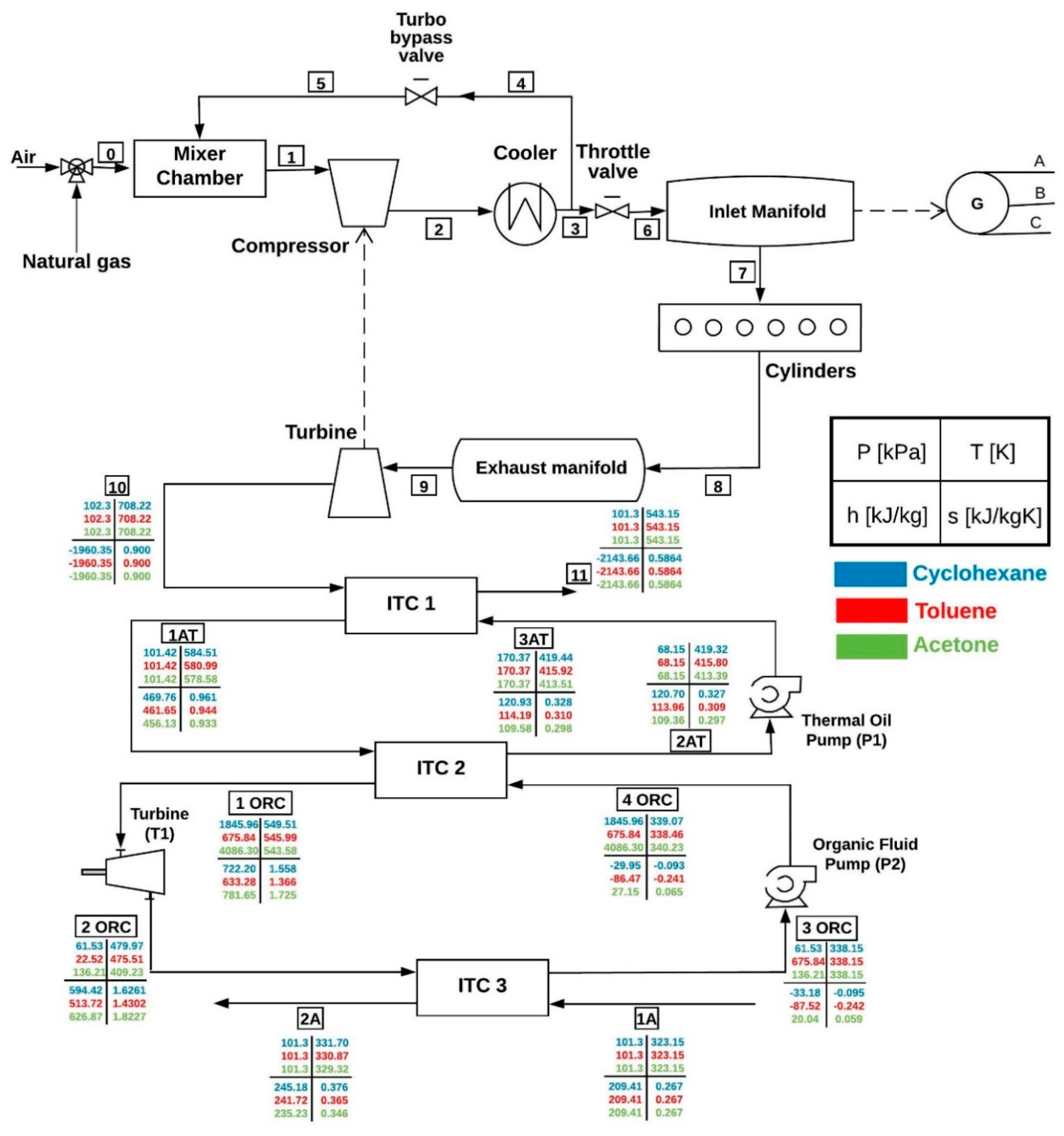
This research evaluated, from an exergy, economic, and environmental impact assessment, the possibility of waste heat recovery to generate electricity from an organic Rankine cycle integrated into a natural gas engine Jenbacher JMS 612 GS-N, which is in operation in the city of Barranquilla-Colombia.
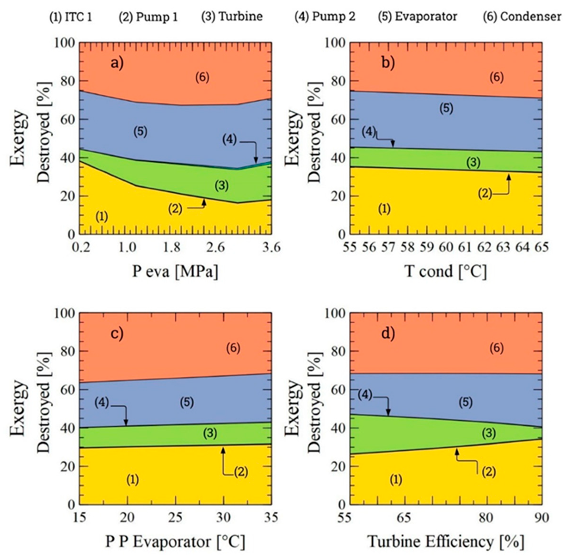
The main contribution of this study was to identify the operational and design variables that most contribute to the exergetic, economic, and environmental performance of the system. It identified the equipment that presents greater exergy destruction varying the different operation parameters, which require us to focus efforts to find greater use of the energy, which contributes to the technical and economic viability of the implementation of this solution in real operational scenarios.
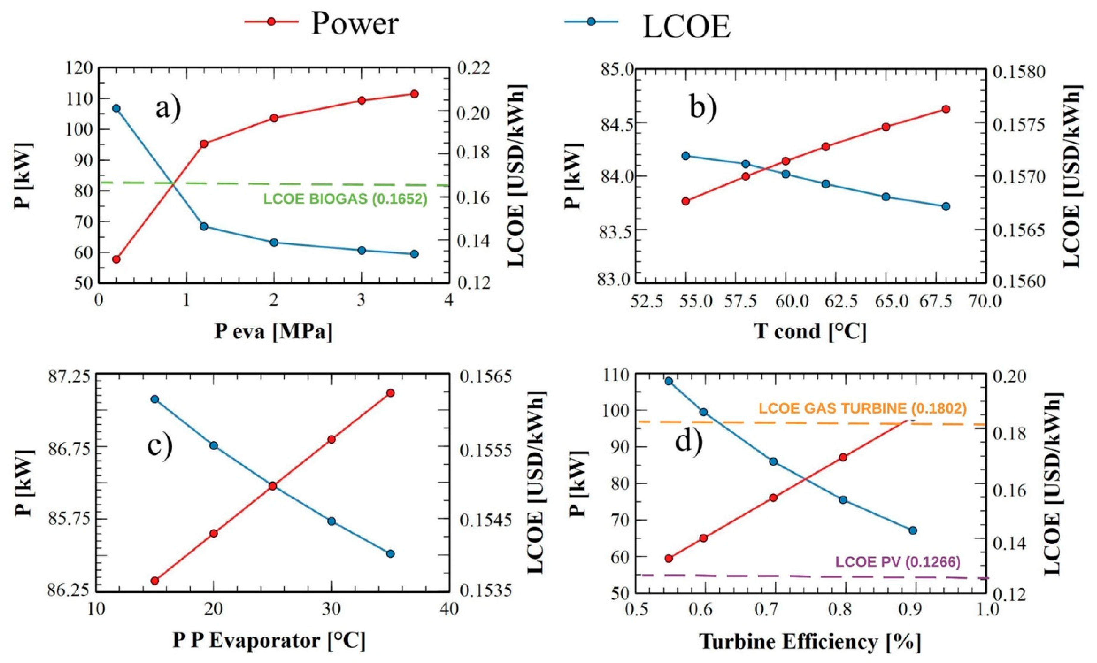
From the parametric results, it was found that the evaporation pressure is the one that has the greatest influence on the exergy destruction. Additionally, it was established that the highest fraction of exergy destroyed was obtained for the ITC1, which is the device with greater opportunities for improvement since it represents approximately more than one-third (38%) of the total exergy destruction of the system. In addition, the high value of the heat transfer area increases its acquisition costs and the LCOE of the thermal system, which, in some operating conditions, exceeds the leveled costs of generating other energy. Therefore, the greatest effort should be aimed to reduce the exergy destroyed cost in the heat exchanger equipment. In addition, the optimal sizes of these types of equipment under the different organic fluid evaluated in this configuration should be studied from the commercial information on the geometric characteristics of the plate heat exchanger, and shell and tube heat exchanger, to reduce the purchase equipment cost, LCOE, and the environmental impact of the system.
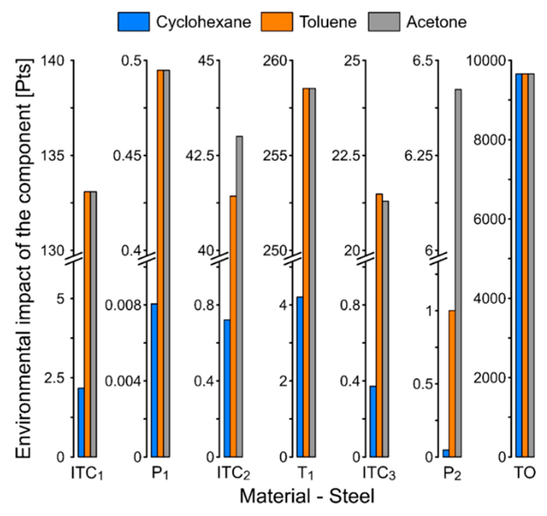
The thermal oil pump (P1) is the equipment that has the lowest exergy efficiency from all the system components, Cyclohexane (15.85%), Toluene (15.60%), and Acetone (15.43%). However, among the heat exchangers equipment, the condenser (ITC3), which has the lowest exergetic efficiency for the different fluids evaluated (Cyclohexane (44.02%), Toluene (46.53%), and Acetone (59.27%)), also stands out because the organic fluid cannot reach the temperatures at which the gases are in the engine exhaust line since there are limitations to thermal stability. Therefore, these alternatives present better results with a low and medium temperature of the waste gases. It is necessary to explore the use of zeotropic mixtures with lower environmental impacts as organic fluid.
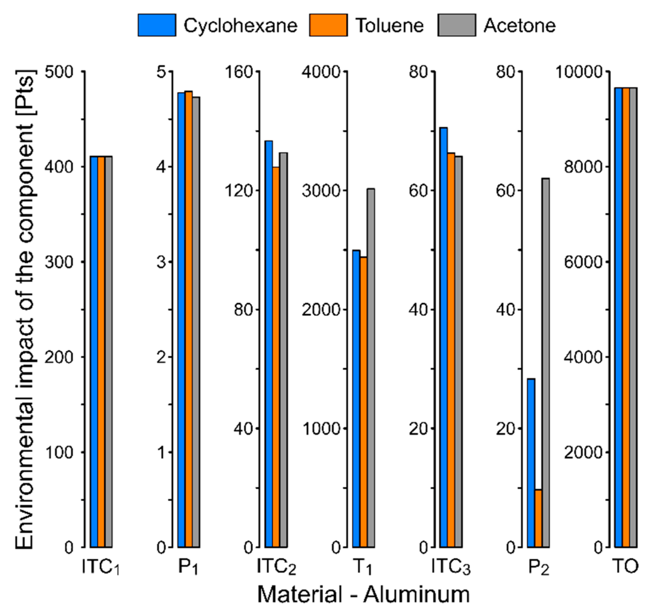
From the exergetic and thermo-economic results, it can be concluded that these systems must have a turbine technology with efficiency not greater than 90% since, from this value, the LCOE of the system exceeds the LCOE of the gas turbine, which affects the implementation of these systems in the Colombian industrial sector. Thus, the component with the greatest environmental impact was the turbine, which reached a maximum value of 3013.65 Pts when the material is aluminum, and the organic working fluid is Acetone. This result was obtained when selecting aluminum as a material. The environmental impacts of the components were greater since the Eco 99 coefficient is greater for aluminum than steel.

Author Contributions

Conceptualization: G.V.O. Methodology: G.V.O. and J.C.G. Software: G.V.O., J.C.G., and J.D.F. Validation: G.V.O., J.C.G., and J.D.F. Formal Analysis: G.V.O., J.C.G., and J.D.F. Investigation: G.V.O. Resources: G.V.O. and J.D.F. Writing—Original Draft Preparation: G.V.O. and J.C.G. Writing—Review & Editing: J.D.F. and J.C.G. Funding Acquisition: G.V.O. All authors have read and agreed to the published version of the manuscript.

Funding

The Universidad del Atlántico and Universidad Francisco de Paula Santander supported this work.

Conflicts of Interest

The authors declare no conflict of interest.

Nomenclature

Q ˙ Heat rate (kW)
W ˙ Power (kW)
m ˙ Mass flow rate (kW)
h Enthalpy (kJ/kg·K)
s Specific entropy (kJ/kg·K)
e x Exergy rate
E ˙ x Exergy destruction rate
η Efficiency
M Mass (kg)
A Area (m)
δ Thickness (m)
F T Correction factor
Y i Environmental Impact (mPts)
coConstruction
OmOperation
Dedecommissioning
WfWorking fluid
CELFConstant escalation leveling factor
CRFCost return factor
ITC1Shell and tube heat exchanger
ITC2Evaporator heat exchanger
ITC3Condenser heat exchanger
T1Turbine 1
P1Thermal oil pump
P2Organic fluid pump
LCOELevelized cost of energy
LCALife cycle assessment
ORCOrganic Rankine cycle

References

  1. Barrozo, F.; Valencia, G.; Cárdenas, Y. An economic evaluation of renewable and conventional electricity generation systems in shopping center using HOMER Pro. Contemp. Eng. Sci. 2017, 10, 1287–1295. [Google Scholar]
  2. Zhang, H.; Guan, X.; Ding, Y.; Liu, C. Emergy analysis of Organic Rankine Cycle (ORC) for waste heat power generation. J. Clean. Prod. 2018, 183, 1207–1215. [Google Scholar] [CrossRef]
  3. Valencia, G.; Acevedo, C.; Duarte, J. Thermoeconomic optimization with PSO Algorithm of waste heat recovery systems based on Organic Rankine Cycle system for a natural gas engine. Energies 2019, 21, 4165. [Google Scholar] [CrossRef] [Green Version]
  4. Valencia, G.; Fontalvo, A.; Cárdenas, Y.; Duarte, J.; Isaza, C. Energy and exergy analysis of different exhaust waste heat recovery systems for natural gas engine based on ORC. Energies 2019, 12, 2378. [Google Scholar] [CrossRef] [Green Version]
  5. Zhai, H.; An, Q.; Shi, L.; Lemort, V.; Quoilin, S. Categorization and analysis of heat sources for Organic Rankine Cycle systems. Renew. Sustain. Energy Rev. 2016, 64, 790–805. [Google Scholar] [CrossRef]
  6. Liu, X.; Liang, J.; Xiang, D.; Yang, S.; Qian, Y. A proposed coal-to-methanol process with CO2 capture combined Organic Rankine Cycle (ORC) for waste heat recovery. J. Clean. Prod. 2016, 129, 53–64. [Google Scholar] [CrossRef]
  7. Gholamian, E.; Habibollahzade, A.; Zare, V. Development and multi-objective optimization of geothermal-based Organic Rankine Cycle integrated with thermoelectric generator and proton exchange membrane electrolyzer for power and hydrogen production. Energy Convers. Manag. 2018, 174, 112–125. [Google Scholar] [CrossRef]
  8. Yao, S.; Zhang, Y.; Yu, X. Thermo-economic analysis of a novel power generation system integrating a natural gas expansion plant with a geothermal ORC in Tianjin, China. Energy 2018, 164, 602–614. [Google Scholar] [CrossRef]
  9. Dimitrova, Z.; Lourdais, P.; Maréchal, F. Performance and economic optimization of an organic rankine cycle for a gasoline hybrid pneumatic powertrain. Energy 2015, 86, 574–588. [Google Scholar] [CrossRef]
  10. Vivian, J.; Manente, G.; Lazzaretto, A. A general framework to select working fluid and configuration of ORCs for low-to-medium temperature heat sources. Appl. Energy 2015, 156, 727–746. [Google Scholar] [CrossRef]
  11. Yu, H.; Feng, X.; Wang, Y. A new pinch based method for simultaneous selection of working fluid and operating conditions in an Organic Rankine Cycle (ORC) recovering waste heat. Energy 2015, 90, 36–46. [Google Scholar] [CrossRef]
  12. Invernizzi, C.M.; Iora, P.; Preißinger, M.; Manzolini, G. HFOs as substitute for R-134a as working fluids in ORC power plants: A thermodynamic assessment and thermal stability analysis. Appl. Therm. Eng. 2016, 103, 790–797. [Google Scholar] [CrossRef]
  13. Mavrou, P.; Papadopoulos, A.I.; Stijepovic, M.Z.; Seferlis, P.; Linke, P.; Voutetakis, S. Novel and conventional working fluid mixtures for solar Rankine cycles: Performance assessment and multi-criteria selection. Appl. Therm. Eng. 2015, 75, 384–396. [Google Scholar] [CrossRef]
  14. Rahbar, K.; Mahmoud, S.; Al-Dadah, R.K.; Moazami, N.; Mirhadizadeh, S.A. Review of organic Rankine cycle for small-scale applications. Energy Convers. Manag. 2017, 134, 135–155. [Google Scholar] [CrossRef]
  15. Karellas, S.; Braimakis, K. Energy–exergy analysis and economic investigation of a cogeneration and trigeneration ORC–VCC hybrid system utilizing biomass fuel and solar power. Energy Convers. Manag. 2016, 107, 103–113. [Google Scholar] [CrossRef]
  16. Pang, K.-C.; Chen, S.-C.; Hung, T.-C.; Feng, Y.-Q.; Yang, S.-C.; Wong, K.-W.; Lin, J.-R. Experimental study on organic Rankine cycle utilizing R245fa, R123 and their mixtures to investigate the maximum power generation from low-grade heat. Energy 2017, 133, 636–651. [Google Scholar] [CrossRef]
  17. Wang, J.; Diao, M.; Yue, K. Optimization on pinch point temperature difference of ORC system based on AHP-Entropy method. Energy 2017, 141, 97–107. [Google Scholar] [CrossRef]
  18. Mahmoudi, S.M.S.; Ghavimi, A.R. Thermoeconomic analysis and multi objective optimization of a molten carbonate fuel cell—Supercritical carbon dioxide—Organic Rankin Cycle integrated power system using liquefied natural gas as heat sink. Appl. Therm. Eng. 2016, 107, 1219–1232. [Google Scholar] [CrossRef]
  19. Zhang, Q.; Ogren, R.M.; Kong, S.-C. Thermo-economic analysis and multi-objective optimization of a novel waste heat recovery system with a transcritical CO2 cycle for offshore gas turbine application. Energy Convers. Manag. 2018, 172, 212–227. [Google Scholar] [CrossRef]
  20. Liu, C.; He, C.; Gao, H.; Xie, H.; Li, Y.; Wu, S.; Xu, J. The environmental impact of organic Rankine cycle for waste heat recovery through life-cycle assessment. Energy 2013, 56, 144–154. [Google Scholar] [CrossRef]
  21. Cioccolanti, L.; Rajabi Hamedani, S.; Villarini, M. Environmental and energy assessment of a small-scale solar Organic Rankine Cycle trigeneration system based on compound parabolic collectors. Energy Convers. Manag. 2019, 198, 111829. [Google Scholar] [CrossRef]
  22. Ding, Y.; Liu, C.; Zhang, C.; Xu, X.; Li, Q.; Mao, L. Exergoenvironmental model of Organic Rankine Cycle system including the manufacture and leakage of working fluid. Energy 2018, 145, 52–64. [Google Scholar] [CrossRef]
  23. Heberle, F.; Schifflechner, C.; Brüggemann, D. Life cycle assessment of Organic Rankine Cycles for geothermal power generation considering low-GWP working fluids. Geothermics 2016, 64, 392–400. [Google Scholar] [CrossRef]
  24. Sun, W.; Yue, X.; Wang, Y. Exergy efficiency analysis of ORC (Organic Rankine Cycle) and ORC-based combined cycles driven by low-temperature waste heat. Energy Convers. Manag. 2017, 135, 63–73. [Google Scholar] [CrossRef]
  25. Mateu-Royo, C.; Mota-Babiloni, A.; Navarro-Esbrí, J.; Peris, B.; Molés, F.; Amat-Albuixech, M. Multi-objective optimization of a novel reversible High-Temperature Heat Pump-Organic Rankine Cycle (HTHP-ORC) for industrial low-grade waste heat recovery. Energy Convers. Manag. 2019, 197, 111908. [Google Scholar] [CrossRef]
  26. Van Kleef, L.M.T.; Oyewunmi, O.A.; Markides, C.N. Multi-objective thermo-economic optimization of Organic Rankine Cycle (ORC) power systems in waste-heat recovery applications using computer-aided molecular design techniques. Appl. Energy 2019, 251, 112513. [Google Scholar] [CrossRef]
  27. Shi, L.; Shu, G.; Tian, H.; Deng, S. A review of modified Organic Rankine Cycles (ORCs) for internal combustion engine waste heat recovery (ICE-WHR). Renew. Sustain. Energy Rev. 2018, 92, 95–110. [Google Scholar] [CrossRef]
  28. Valencia, G.; Duarte, J.; Isaza-Roldan, C. Thermoeconomic analysis of different exhaust waste-heat recovery systems for natural gas engine based on ORC. Appl. Sci. 2019, 9, 4071. [Google Scholar] [CrossRef] [Green Version]
  29. Da Silva, J.A.M.; Seifert, V.; de Morais, V.O.B.; Tsolakis, A.; Herreros, J.; Torres, E. Exergy evaluation and ORC use as an alternative for efficiency improvement in a CI-engine power plant. Sustain. Energy Technol. Assess. 2018, 30, 216–223. [Google Scholar] [CrossRef]
  30. Abam, F.I.; Ekwe, E.B.; Effiom, S.O.; Ndukwu, M.C. A comparative performance analysis and thermo-sustainability indicators of modified low-heat Organic Rankine Cycles (ORCs): An exergy-based procedure. Energy Rep. 2018, 4, 110–118. [Google Scholar] [CrossRef]
  31. Karvountzis-Kontakiotis, A.; Pesiridis, A.; Zhao, H.; Alshammari, F.; Franchetti, B.; Pesmazoglou, I.; Tocci, L. Effect of an ORC Waste Heat Recovery System on Diesel Engine Fuel Economy for Off-Highway Vehicles; SAE Technical Paper; SAE: Warrendale, PA, USA, 2017. [Google Scholar]
  32. Ochoa, G.V.; Peñaloza, C.A.; Rojas, J.P. Thermoeconomic modelling and parametric study of a simple orc for the recovery ofwaste heat in a 2 MW gas engine under differentworking fluids. Appl. Sci. 2019, 9, 4526. [Google Scholar] [CrossRef] [Green Version]
  33. Khoo, H.H. LCA of plastic waste recovery into recycled materials, energy and fuels in Singapore. Resour. Conserv. Recycl. 2019, 145, 67–77. [Google Scholar] [CrossRef]
  34. Shyam Mishra, R.; Khan, Y. Exergy and energy analysis of modified organic rankine cycle for reduction of global warming and ozone depletion. Int. J. Res. Eng. Innov. 2017, 1, 1–12. [Google Scholar]
  35. Ochoa, G.V.; Isaza-Roldan, C.; Forero, J.D. A phenomenological base semi-physical thermodynamic model for the cylinder and exhaust manifold of a natural gas 2-megawatt four-stroke internal combustion engine. Heliyon 2019, 5, e02700. [Google Scholar] [CrossRef] [PubMed] [Green Version]
  36. Water, G.P. Jenbacher 612 GS-N. L 2MW. Tech. Specif. 2011, 1–4. Available online: http://kts-eng.com/assets/files/J-612.pdf (accessed on 28 December 2019).
  37. Barrozo, F.; Ochoa, G.V.; Cárdenas, Y.D. Hybrid PV & Wind grid-connected renewable energy system to reduce the gas emission and operation cost. Contemp. Eng. Sci. 2017, 26, 1269–1278. [Google Scholar]
  38. Zare, V. A comparative exergoeconomic analysis of different ORC configurations for binary geothermal power plants. Energy Convers. Manag. 2015, 105, 127–138. [Google Scholar] [CrossRef]
  39. El-Emam, R.S.; Dincer, I. Exergy and exergoeconomic analyses and optimization of geothermal organic Rankine cycle. Appl. Therm. Eng. 2013, 59, 435–444. [Google Scholar] [CrossRef]
  40. Calise, F.; Capuozzo, C.; Carotenuto, A.; Vanoli, L. Thermoeconomic analysis and off-design performance of an organic Rankine cycle powered by medium-temperature heat sources. Sol. Energy 2014, 103, 595–609. [Google Scholar] [CrossRef]
  41. Voros, N.G.; Kiranoudis, C.T.; Maroulis, Z.B. Solar energy exploitation for reverse osmosis desalination plants. Desalination 1998, 115, 83–101. [Google Scholar] [CrossRef]
  42. Valencia, G.; Benavides, A.; Cárdenas, Y. Economic and Environmental Multiobjective Optimization of a Wind–Solar–Fuel Cell Hybrid Energy System in the Colombian Caribbean Region. Energies 2019, 12, 2119. [Google Scholar] [CrossRef] [Green Version]
  43. Shengjun, Z.; Huaixin, W.; Tao, G. Performance comparison and parametric optimization of subcritical Organic Rankine Cycle (ORC) and transcritical power cycle system for low-temperature geothermal power generation. Appl. Energy 2011, 88, 2740–2754. [Google Scholar] [CrossRef]
  44. Bhatt, A.; Bradford, A.; Abbassi, B.E. Cradle-to-grave life cycle assessment (LCA) of low-impact-development (LID) technologies in southern Ontario. J. Environ. Manag. 2019, 231, 98–109. [Google Scholar] [CrossRef] [PubMed]
  45. International Organization for Standardization (ISO). Environmental Management The ISO 14000 Family of International Standards ISO in Brief ISO and the Environment; ISO: Geneva, Switzerland, 2009. [Google Scholar]
  46. Arvanitoyannis, I.S. Life cycle assessment (LCA)—Principles and guidelines. Waste Manag. Food Ind. 2008, 14040, 97–132. [Google Scholar]
  47. Kost, C.; Schlegl, T.; Thomsen, J.; Nold, S.; Mayer, J.; Hartmann, N.; Senkpiel, C.; Philipps, S.; Lude, S.; Saad, N. Fraunhofer ISE: Levelized cost of electricity—Renewable energy technologies, March 2018. arXiv 2018, arXiv:cs/9605103. Available online: https://www.ise.fraunhofer.de/content/dam/ise/en/documents/publications/studies/EN2018_Fraunhofer-ISE_LCOE_Renewable_Energy_Technologies.pdf (accessed on 28 December 2019).
  48. Valencia, G.; Núñez, J.; Duarte, J. Multiobjective optimization of a plate heat exchanger in a waste heat recovery organic rankine cycle system for natural gas engines. Entropy 2019, 21, 655. [Google Scholar] [CrossRef] [Green Version]
  49. Diaz, G.A.; Forero, J.D.; Garcia, J.; Rincon, A.; Fontalvo, A.; Bula, A.; Padilla, R.V. Maximum Power From Fluid Flow by Applying the First and Second Laws of Thermodynamics. J. Energy Resour. Technol. 2017, 139, 032903. [Google Scholar] [CrossRef]
  50. Valencia, G.; Vanegas, M.; Villicana, E. Disponibilidad Geográfica y Temporal de la Energía Solar en la Costa Caribe Colombiana; Sello editorial de la Universidad del Atlántico: Barranquilla, Colombia, 2016. [Google Scholar]
Figure 1. Waste heat recovery system based on ORC.
Resources 09 00002 g001
Figure 2. Geometric configuration for tube and shell heat exchangers.
Resources 09 00002 g002
Figure 3. Geometric configuration of plate heat exchanger (condenser and evaporator) [3].
Resources 09 00002 g003
Figure 4. Life cycle assessment system boundary diagram.
Resources 09 00002 g004
Figure 5. Destruction of exergy by the component using the cyclohexane as working fluid depending on (a) evaporator pressure, (b) condenser temperature, (c) evaporator pinch point, and (d) turbine efficiency.
Resources 09 00002 g005
Figure 6. Effect of (a) evaporator pressure, (b) condenser temperature, (c) evaporator pinch point, and (d) turbine efficiency, on net power and LCOE using the cyclohexane as working fluid.
Resources 09 00002 g006
Figure 7. Environmental impact of the components with steel as material.
Resources 09 00002 g007
Figure 8. Environmental impact of the components with aluminum as material.
Resources 09 00002 g008
Figure 9. Environmental impact of the working fluids.
Resources 09 00002 g009
Table 1. Natural gas engine parameter [36].
ItemsParametersUnits
Cylinder capacity74.852L
Compression ratio10.5-
Number of cylinders (In V–60°)12-
Air intake typeTurbocharged-
Diameter in the chamber190mm
Maximum torque60.66kN·m
Power at nominal speed1820kW
Nominal speed1500rpm
Ignition typeSpark ignition-
Operation range1000–1982kW
Output temperature580–650°C
Table 2. Exergy efficiency, exergy destruction, and exergy destruction ratio of components and heat exchanger area.
Shell and Tube Heat Exchanger (ITC1)Evaporator Heat Exchanger (ITC2)Condenser Heat Exchanger (ITC3)
CyclohexaneTolueneAcetoneCyclohexaneTolueneAcetoneCyclohexaneTolueneAcetone
Qi (kW)514.85514.85514.85515.23515.23515.23429.91430.39414.38
Ai (m2)88.7088.7088.7029.5127.6128.6615.2314.3114.19
εi (%)83.5582.8582.3884.1882.0085.0444.0246.5359.27
ED,k (kW)40.2441.9543.1032.3536.5130.1640.4936.0520.13
yD,k (%)31.4532.5437.4925.2928.3226.2431.6427.9717.51
Thermal Oil Pump (P1)Organic Fluid Pump (P2)Turbine (T1)
CyclohexaneTolueneAcetoneCyclohexaneTolueneAcetoneCyclohexaneTolueneAcetone
W (kW)0.370.370.372.210.754.8587.5385.58105.70
εi (%)15.8515.6015.4377.6377.6077.6986.1786.0383.98
ED,k (kW)0.310.310.310.490.161.0814.0313.8920.15
yD,k (%)0.240.240.270.380.130.9010.9710.7717.50
Cyclohexane Toluene Acetone
WNET (kW)84.94 84.45 100.46
nth ORC16.49 16.40 19.51
nexer-overall34.70 34.50 41.04
Table 3. Relative data of working fluids in each life cycle phase.
LCA PhaseDescriptionOrganic FluidThermal Oil
CyclohexaneTolueneAcetone
Construction PhaseOrganic fluid filling amount (kg)487.55476.73588.74184
Operation PhaseOrganic fluid leakage amount (kg)48.7547.6758.8718
Decommissioning PhaseOrganic fluid emission loose amount (kg)13.1612.8715.895
Table 4. Results of LCA for each component with steel as a material.
Working FluidComponentMaterialw (mPts/kg)Quality (kg)Yco (mPts)Yom (mPts)Yde (mPts)Y (mPts)
CyclohexaneITC1Steel861407127,03706049133,086
P1Steel865472022495
ITC2Steel8646842,2760201344,289
T1Steel862733246,768011,751258,519
ITC3Steel8624221,8250103922,865
P2Steel8631279901332933
Thermal OilDiphenyl-oxide46,4671848,568,515856,851231,3509,656,716
FluidCyclohexane263993245,687.6224,568.766634276,890
TolueneITC1Steel861407127,036.7106049133,086
P1Steel865472.27022495
ITC2Steel8643839,545.830188341,429
T1Steel862733246,768.04011,751258,519
ITC3Steel8622720,505.05097621,481
P2Steel8611955.970461002
Thermal OilDiphenyl-oxide46,4671848,568,515856,851231,3509,656,716
FluidToluene268091244,290.5124,429.058051276,770
AcetoneITC1Steel861407127,036,7106049133,086
P1Steel865472.27022495
ITC2Steel8645541,045.800195543,000
T1Steel862733246,768.04011,751258,519
ITC3Steel8622520,325.20096821,293
P2Steel86686131.3702926423
Thermal OilDiphenyl-oxide46,4671848,568,515856,851231,3509,656,716
FluidAcetone5426111603,695.3860,369.5316,300680,365
Table 5. Results of LCA for each component with aluminum as the material.
Working FluidComponentMaterialw (mPts/kg)Quality (kg)Yco (mPts)Yom (mPts)Yde (mPts)Y (mPts)
CyclohexaneITC1Aluminum780479392,065018,670410,735
P1Aluminum7806455902174776
ITC2Aluminum780159130,47506213136,688
T1Aluminum78029092,382,2240113,4392,495,663
ITC3Aluminum7808267,3580320870,566
P2Aluminum7803327,0220128728,308
Thermal OilDiphenyl Oxide46,4671848,568,515856,851231,3509,656,716
FluidCyclohexane26394881,287,783.2128,660.8434,7381,451,182
TolueneITC1Aluminum780479392,065.41018,670410,735
P1Aluminum78064572.8302184791
ITC2Aluminum780149122,047.8205812127,860
T1Aluminum78028442,329,362.990110,9222,440,285
ITC3Aluminum7807763,283.470301366,297
P2Aluminum780119227.9004399667
Thermal OilDiphenyl Oxide46,4671848,568,515856,851231,3509,656,716
FluidToluene26804771,278,264.60127,755.7642,5991,448,619
AcetoneITC1Aluminum780479392,065.41018,670410,735
P1Aluminum78064515.1402154730
ITC2Aluminum780155126,677.0906032132,709
T1Aluminum78035122,876,664.600136,9843,013,649
ITC3Aluminum7807762,728.400298765,715
P2Aluminum7807259,185.030281862,003
Thermal OilDiphenyl Oxide46,4671848,568,515856,851231,3509,656,716
FluidAcetone54265893,195,619.50319,425.7786,2453,601,290

