Article

Thermal Mapping and Heat Transfer Analysis of an Induction Motor of an Electric Vehicle Using Nanofluids as a Cooling Medium

by
Gaurav Kumar Pandey
1,
Siddharth Sriram Sikha
1,
Abhineet Thakur
1,
Sai Sravan Yarlagadda
1,
Sai Santosh Thatikonda
1,
Bibin Baiju suja
1,
Arkadiusz Mystkowski
2,*,
Egidijus Dragašius
3 and
Edison Gundabattini
4,*
1
School of Mechanical Engineering, Vellore Institute of Technology (VIT), Vellore 632 014, India
2
Faculty of Electrical Engineering, Bialystok University of Technology, Wiejska 45D, 15351 Bialystok, Poland
3
Faculty of Mechanical Engineering and Design, Kaunas University of Technology, Studentų Str. 56–326, 44249 Kaunas, Lithuania
4
Department of Thermal and Energy Engineering, School of Mechanical Engineering, Vellore Institute of Technology (VIT), Vellore 632 014, India
*
Authors to whom correspondence should be addressed.
Sustainability 2023, 15(10), 8124; https://0-doi-org.brum.beds.ac.uk/10.3390/su15108124
Submission received: 10 April 2023 / Revised: 8 May 2023 / Accepted: 12 May 2023 / Published: 17 May 2023
(This article belongs to the Topic Nanomaterials for Sustainable Energy Applications)

Abstract

:
The driving motor is one of the most crucial components of an electric vehicle (EV). The most commonly used type of motor in EVs is the induction motor. These motors generate heat during operation due to the flow of electrical current through the motor’s coils, as well as friction and other factors. For long-run and high efficiency of the motor, cooling becomes more important. This article utilized ANSYS Motor-CAD to map the temperature signature of an induction motor and investigated the thermal efficiency of using nanofluids as a cooling medium. The thermal conductivity of nanofluids has been found to be superior to that of more conventional cooling fluids such as air and water. This research explores the effect of using Al2O3, ZnO, and CuO concentrations in nanofluids (water as a base fluid) on the thermal efficacy and performance of motor. According to the findings, using nanofluids may considerably increase the efficiency of the motor, thereby lowering temperature rise and boosting system effectiveness. Based on the simulation analysis using ANSYS Motor-CAD, the results demonstrate that the utilization of CuO nanofluid as a cooling medium in the induction motor led to a reduction of 10% in the temperature of the motor housing. The maximum reduction in the temperature was found up to 10% when nanofluids were used, which confirms CuO as an excellent option of nanofluids for use as motor cooling and other applications where effective heat transmission is crucial.

1. Introduction

The popularity of electric vehicles around the globe is increasing gradually. Electric vehicles help in reducing carbon footprints as they are less polluting than the conventional petrol or diesel-operated vehicles. Electric vehicles also help in reducing our dependence on exhausting fossil fuels. EVs operate at an efficiency of about 60% which is much greater than the petrol or diesel cars which have an efficiency between 17% and 21%.

1.1. Induction Motor in Context of Electric Vehicle

Induction motors are the devices that convert electrical energy into mechanical energy. Induction motors offer wider torque range and accurate speed control, provide recharging of battery during breaking, require low maintenance, and have high efficiency [1]. They are also smaller in size when compared with permanent magnet DC (Direct Current) motors and are less expensive, Figure 1.

1.2. Hot Spots in Induction Motor Heat Generation

One of the main challenges faced by induction motors is thermal management. The induction motors utilized in cars require high load capacity. When these motors operate at higher speeds, they generate heat which results in an increase in losses such as copper and iron loss, thereby increasing the temperature in the rotor and stator of the motor [1]. With the increase in temperature, various parts of the induction motor could experience phase change, softening, melting, and other forms of degradation that will affect the performance of the motor. Increases in motor temperature also result in the development of thermal stress in various parts of the motor that results in cracking, material deformation, and fatigue failure. Hence, the performance and life span of the induction motor are dependent on its thermal conditions. The induction motor’s temperature rises as a result of heat sources such as stator’s iron losses, mechanical and windage loss, and winding joule loss [3,4]. Currently, induction motors are cooled using techniques such as air cooling, water cooling, and air–water cooling. However, these methods become less efficient with the use of improved technologies in induction motors. The heat produced inside the motor is transferred through the finned outer surface of the motor [5]. The objective of this paper is to investigate more efficient methods for cooling induction motors.

1.3. Cooling of an Induction Motor

Cooling is required in an induction motor to prevent the motor from overheating and potentially causing damage or failure. Overheating could lead to motor failure, reduced efficiency, and decreased lifespan [6]. A few methods adopted for motor cooling include air cooling, liquid cooling, and forced convection cooling. Induction motors generate heat during operation due to the flow of electrical current through the motor’s coils, as well as friction and other factors.
If the motor becomes too hot, the insulation around the motor’s wires could begin to break down, leading to electrical shorts and potential damage to the motor’s internal components, Figure 2. Additionally, it is well known that an electric motor could suffer damage from high temperatures as high temperatures could cause the motor’s bearings and other moving parts to expand, which could lead to mechanical failure [7].
The rotor, stator, shaft, housing water jacket, front-end cap, and back-end cap make up the motor. Cooling helps to dissipate the heat produced by the motor, thereby preventing it from reaching damaging temperatures. There are numerous ways to cool an induction motor, including air cooling, liquid cooling, and even passive cooling methods such as natural convection. In terms of cost and cooling uniformity, air cooling is preferable to other techniques; nonetheless, it performs the least well of the three traditional cooling techniques. In the liquid cooling scheme, as the oil flows in, the housing jacket immediately cools the heat source. Hence, liquid/oil cooling is most preferred and has the best cooling performance [8,9,10]. Thus, by managing the motor’s temperature, cooling helps to ensure that the motor operates safely and efficiently, with minimal risk of damage or failure.
There are also several factors that could affect motor cooling, including motor size, operating temperature, and the environment in which the motor is used. Designers must carefully consider these factors when selecting a cooling method for their motor [11].

1.4. Cooling Schemes

Induction motors could be cooled using various methods, each with its own set of benefits and drawbacks. The most widely used technique for cooling motors is air cooling, which involves circulating air around the motor to dissipate heat. This can be accomplished through natural convection, where heat rises and is replaced by cooler air, or forced convection, where a fan or blower is used to move air across the motor. Air-cooled motors are often less expensive and simpler to maintain than liquid-cooled motors but may be less effective in high-temperature environments [12].
Liquid cooling involves the circulation of a liquid coolant around the motor to absorb and dissipate heat. This method is typically more efficient than air cooling and is often used in high-performance applications or where space is limited [13]. However, liquid cooling systems could be more complex and require additional components such as pumps, radiators, and hoses.
Forced convection cooling involves the use of a fan or blower to circulate air around the motor at a higher velocity than natural convection. This method could be used with both air-cooled and liquid-cooled motors to increase cooling efficiency.

1.5. Nanofluids as a Coolant

The term “nanofluid” used to describe the new sort of heat dissipating fluids based on nanotechnology that have thermal features that are better in comparison to their parent fluids or traditional particle fluid suspensions [14]. In recent times, the utilization of nanofluid as a working fluid has gained popularity in enhancing equipment performance. Researchers have successfully employed nanoparticles in cooling systems due to their superior heat transfer and thermophysical properties. The study and examination of materials at a size of up to 100 nm is known as nanotechnology. Base fluids, such as water or oil, are combined with 0.05–1% concentrations or more of nanoparticles ranging in size from 10 to 100 nm.
The ability of nanofluid to conduct and convent heat is proven to have an improved heat transfer coefficient. Metallic nanofluids are frequently utilised to attain higher thermophysical characteristics—for example, viscosity, thermal diffusivity, thermal conductivity, specific heat capacity, and heat transfer coefficients. They have all the aforementioned qualities, which are superior to those of water and oil, which are regarded as base fluids [14]. Nanofluids are colloidal fluids made up of chemically stable nanoparticles that are mixed in a fluid (such as water, refrigerant, or aqueous solutions,) having 0.01% to 10% concentrations (by volume). The most often used and researched nanoparticles include metals (Au, Cu, Fe, Ag, Ti, and others) and elemental oxides (CuO, Al2O3, ZrO2, FeO, SiO2, TiO2, and others).
In a nutshell, a ‘nanofluid’ is a fluid that contains suspended nanoparticles with a size typically less than 100 nm. These fluids have unique thermal properties and are being considered as potential coolants for various applications. According to studies, nanofluids have a greater thermal conductivity than conventional coolants, which could increase cooling effectiveness. The stability of these fluids and their tendency to clog or damage coolant systems are some of their potential concerns. Moreover, nanofluids may be more expensive to produce and use as coolants than conventional coolants, which may restrict their applicability [15].
Even though nanofluids could have certain benefits as coolants, further study and research are required to completely understand their characteristics and possible advantages in diverse cooling applications. This article mainly focuses on the thermal mapping and heat transfer analysis of induction motors used in electric vehicles. This paper also implements the technique for cooling the motor by nanofluids and investigates the thermal performance. The simulation study is performed using ANSYS Motor-CAD. The thermal efficiency of nanofluids with Al2O3, ZnO, and CuO is investigated.

2. Methodology of Analysis

2.1. Nanofluids Materials

In this analysis, water is the base fluid, and Al2O3, ZnO, and CuO are the nanoparticles. The volume concentration of the nanoparticles used for this study is 10%, and the temperature varies from 0 to 60 °C. The Table 1 tabulates the characteristics of nanoparticles.

2.2. Theoretical Analysis of Thermophysical Properties of Nanofluids

The thermophysical properties of nanofluids utilized in this analysis are initially investigated by theoretical model. The thermal conductivity, density, viscosity, and heat capacity are evaluated by following models.
The thermal conductivity of the nanofluids is evaluated by the Hamilton and Crosser Model [16], which is given by
k n f = [ k p + ( n 1 ) k b f ( n 1 ) φ ( k b f k p ) k p + ( n 1 ) k b f + φ ( k b f k p ) ] k b f
Pak and Cho’s model [17] is used to identify the density and heat capacity of the fluids.
ρ n f = ( 1 φ ) ρ b f + φ ρ p
c p n f = ( 1 φ ) c p b f + φ c p p
The viscosity of the nanofluids is determined by Einstein’s formula [18]:
μ n f μ b f = 1 + 2.5 φ

2.3. Numerical Analysis

2.3.1. Physics and Equations

In a single-phase induction motor heat transfer network analysis, the basic principles of heat transfer are the following:
Conductive heat transfer: The heat conduction equation, a partial differential equation, illustrates the temporal movement of heat energy in the motor. Conduction is how heat is transferred through solid objects such as the stator and rotor, and it may be stated as follows [19]:
ρ c T t = x ( λ x T x ) + y ( λ y T y ) + z ( λ z T z ) + Q
The left-hand side of the equation represents the rate of change of thermal energy in the material, which in this case is the motor. On the right-hand side, the movement of heat energy caused by conduction is depicted, where heat flows from hotter regions to cooler ones. Fourier’s law is used to relate the heat flow and the temperature gradient. The heat flux q is given by [20].
q = λ T x
Conductive heat transfer: Fluid motion is used to transfer heat from one location to another. Convection’s equation may be written as follows [20]:
q = α . A s ( T w T )
The formula describes the rate of heat transfer between a solid surface and a moving fluid (such as water or nanofluid) due to convection. It is derived from Newton’s law of cooling, which states that the coefficient of convective heat transfer and the temperature difference between the solid surface and the moving fluid determine the rate at which heat is transferred between them [21].
Radiation is not taken into consideration in the thermal assessment of a single-phase induction motor; only conduction and convection are taken into account.

2.3.2. Simulation Procedure

The process of conducting the simulations and analysis of this work is shown in Figure 3.

2.3.3. Boundary Condition and Input Parameter

Table 2, Table 3, Table 4 and Table 5 show motor condition, specifications of the single-phase induction motor, input parameters for thermal analysis on ANSYS, and fluid properties, respectively.

2.3.4. Geometrical Model

The radial and axial views of the induction motor are shown in Figure 4 and Figure 5. The geometrical model is modelled by ANSYS Motor-CAD (version: 15.1.2.1).
A specified fluid was selected as a first step from the Motor-CAD ‘material database’ followed by the designing of the induction motor using ANSYS Motor-CAD (version: 15.1.2.1).

2.4. Cooling Circuit Configuration

There are multiple ways that the induction motor could be cooled based on the thermal management system chosen for the motor, and the configuration of the cooling system could be very important for the proper dissipation of the heat. An air-cooled induction motor chosen in this research has radial fins which increase the surface area available for contact between the heated surface of the motor and the coolant medium, i.e., air in this case.
Compared to air cooling, liquid cooling is considered to be a much more effective technique for dissipating heat due to the use of coolants with superior thermal properties. In this case, nanofluid is used as the coolant, which needs to be circulated through the surface of the motor to absorb the heat being generated. For liquid cooling techniques, there are many configurations available, where coolant is made to pass through various sections of the motors.
In this case, a housing water jacket configuration is employed, where the coolant is circulated through various ducts in the outer surface of the motor. In the current design, 42 channels are integrated in the motor through which the coolant shall be moved and pass through using a pump [22]. Thermal analysis is performed in order to efficiently dispel heat out of the motor, minimizing the possibility of overheating (within the safe limits of operation) and increasing the motor’s lifespan [23,24]. Since it is known that heat transfer takes place by conduction and convection inside the motor, heat transfer by conduction is given by a second order differential equation, and heat transfer by convection is governed by Newton’s law of cooling [25].

3. Results and Discussion

3.1. Thermophysical Characteristics

These thermophysical characteristics principally depend on the parameters of the solid particles as well as the base fluid (water), specifically the volume fraction of nanoparticles in suspension and particle shape. The aforementioned relationships could be utilised to estimate the characteristics of nanofluids.
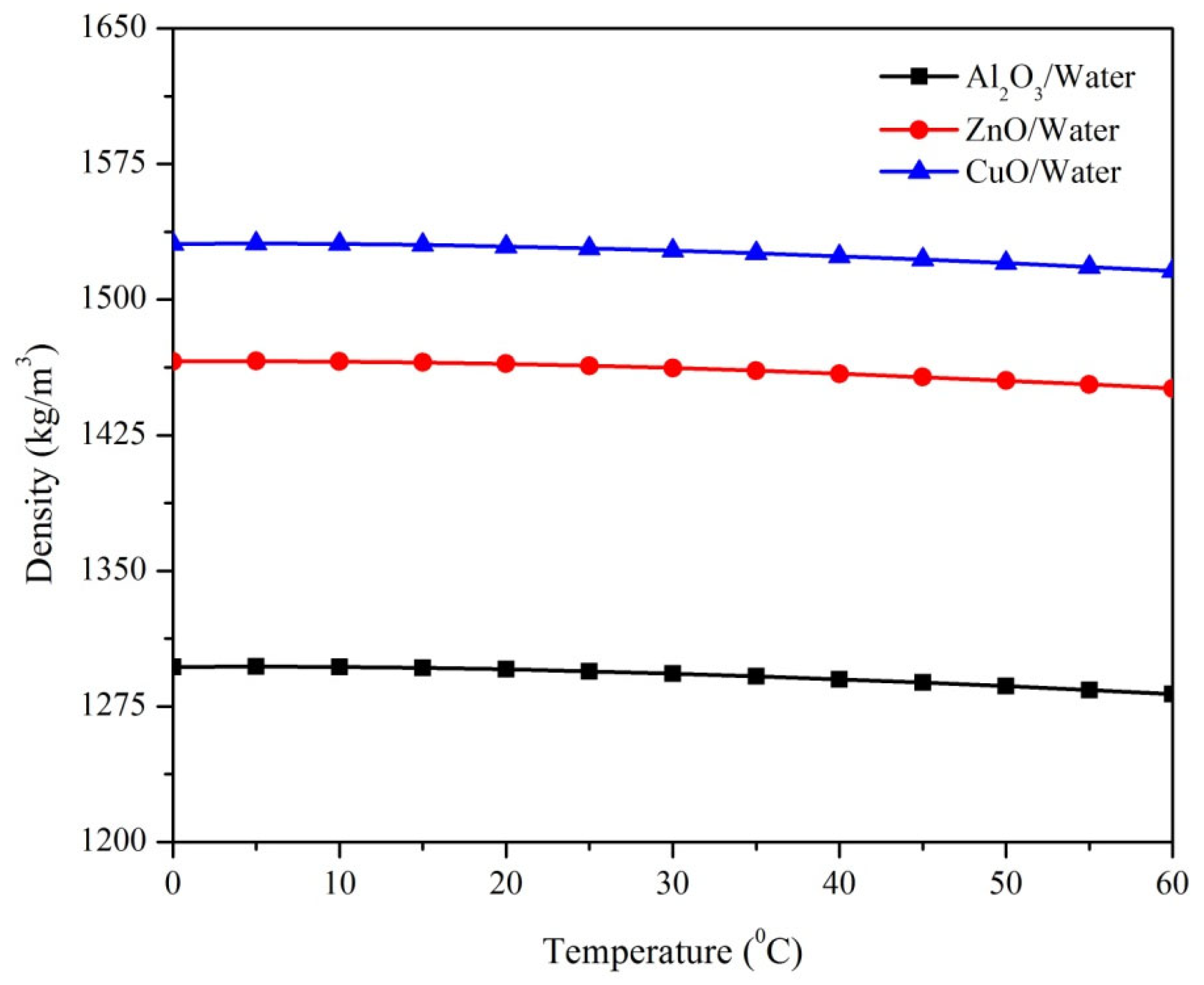
The concentration of nanoparticles, as well as the characteristics of the base fluid, all affect the density of nanofluids. In general, when nanoparticles are added to a base fluid, the density of the nanofluid rises relative to the base fluid. Here, CuO in water shows the maximum density among the three nanofluids. At ambient temperature, there is an increase of 4.45% in density when CuO is compared to ZnO and an increase of 18.1% when CuO is compared to Al2O3. As the concentration of nanoparticles increases, the density of the nanofluid also increases. However, at very high concentrations, the agglomeration and settling of nanoparticles may cause the density of the nanofluid to plateau or even decrease.
As the concentration of nanoparticles in a nanofluid decreases, the particle–particle interactions increase, and the Brownian motion of particles decreases. This causes the kinematic viscosity of the nanofluid to increase. Nevertheless, the impact of nanoparticle concentration on kinematic viscosity is influenced by the base fluid’s characteristics as well as aspects including form, size, and surface chemistry. The kinematic viscosity of nanofluids could also be influenced by temperature and shear rate. The kinematic viscosity of nanofluids reduces as the temperature rises as a result of the fluid’s decreased viscosity. At ambient temperature, there is an increase of 42.94% in viscosity when Al2O3 is compared to ZnO and an increase of 59.1% when Al2O3 is compared to CuO. Here, Al2O3 in water shows the highest kinematic viscosity among the three nanofluids as it has the highest molecular mass, followed by ZnO nanofluid, and the least is shown by CuO nanofluid as it has the least molecular mass, Figure 6 and Figure 7.
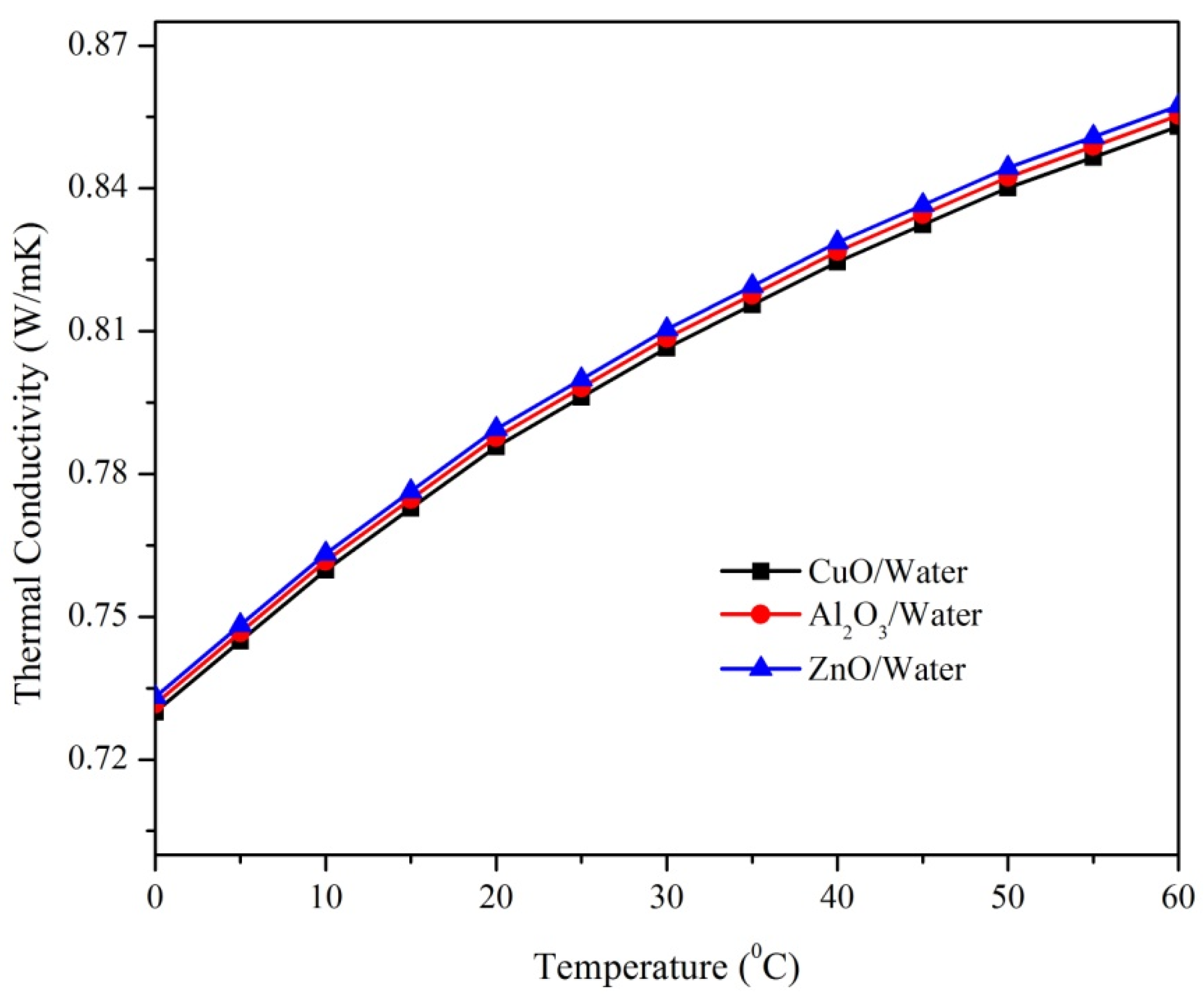
Nanofluids offer higher thermal conductivity than the fluids that are currently being used for motor cooling. The primary reason for this is the Brownian motion, which promotes the formation of nanoparticle clusters even at low concentrations. Among the three nanofluids investigated in the research, the thermal conductivity of the ZnO nanofluid is the highest, followed by Al2O3, while the CuO nanofluid exhibits the lowest thermal conductivity, shown in Figure 8. At ambient temperature, there is an increase of 22.5% in viscosity when ZnO is compared to Al2O3 and an increase of 48.94% when ZnO is compared to CuO. As the temperature of nanofluids increases, the intermolecular force of attraction between liquid molecules also increases. This causes the molecules of the liquid to move apart, leading to a decrease in the thermal conductivity of the nanofluid.
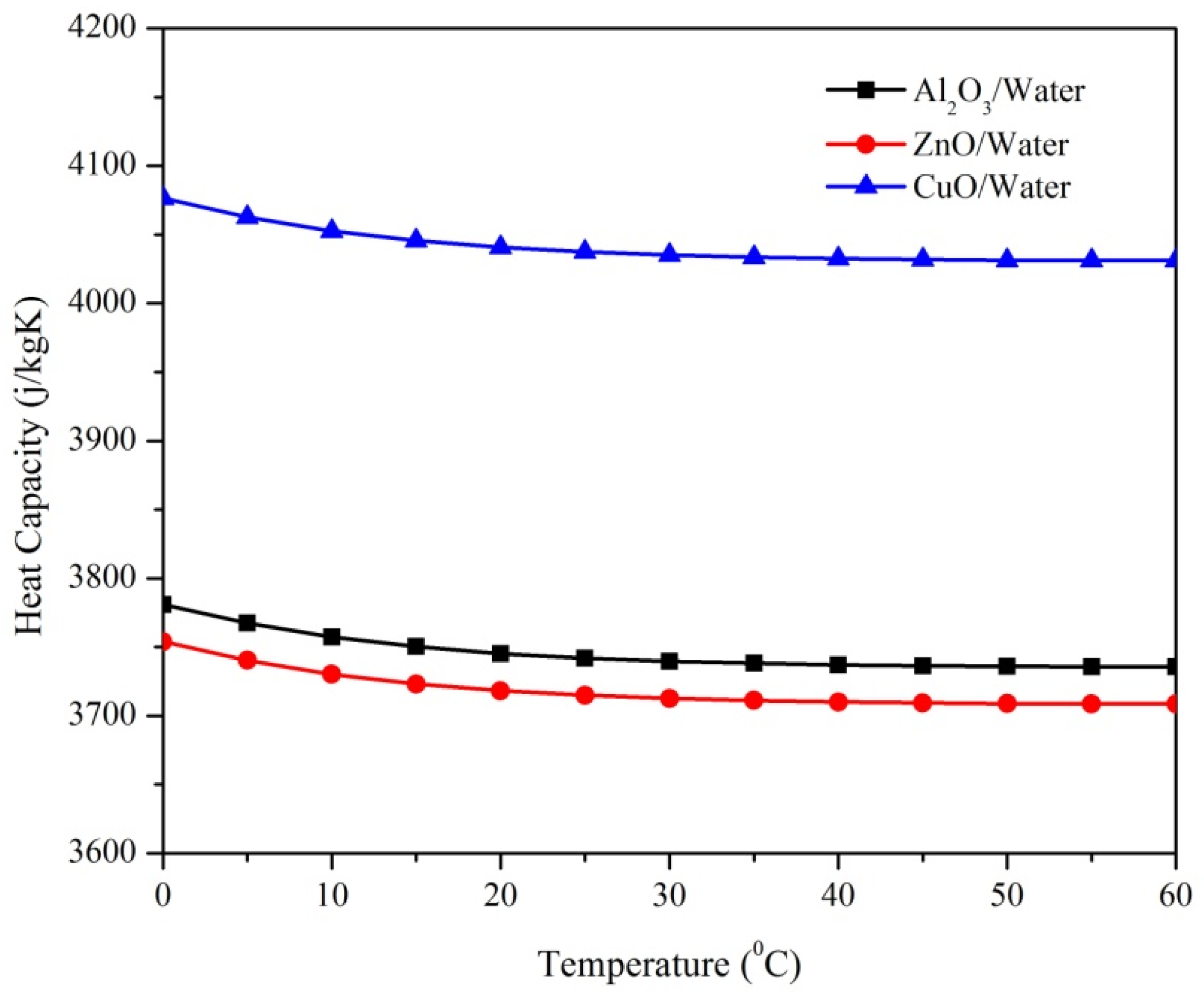
The specific heat capacity of nanofluids could also vary depending on temperature and pressure. The specific heat capacity of nanofluids may change as the temperature increases, due to alterations in the thermophysical characteristics of the base fluid and nanoparticles. At ambient temperature, there is an increase of 7.9% in specific heat capacity when CuO is compared to Al2O3 and an increase of 8.67% when CuO is compared to ZnO. Out of the three nanofluids used for research, the specific heat capacity of CuO nanofluid is highest, followed by Al2O3, and the least is of ZnO. Additionally, due to the compression of the base fluid and nanoparticles under high pressures, nanofluids’ specific heat capacities may be reduced, Figure 9.

3.2. Temperature Distribution

The temperature distribution over induction motor with water, CuO, ZnO, and Al2O3-based nanofluids is shown in Figure 10, Figure 11, Figure 12 and Figure 13, respectively.
The reductions of the temperatures throughout the motor when nanofluids are allowed to flow instead of water are listed. The temperature reductions at the major parts of the motor are then noted in Table 6. The usage of the CuO nanofluid results in a 10% decrease in the temperature of the motor’s housing (front), according to the findings. Since it outperforms the currently used cooling schemes in the industry (such as air cooling or water cooling), the CuO-based nanofluid makes this technique a more effective one for cooling electric motors because it shows the maximum reduction when used as a coolant. The findings also demonstrate that the temperature of the motor components was significantly lowered as compared to the water-based cooling system with nanofluids, as seen in Table 6.
Table 7 (comparison) indicates the percentage temperature drop when water is used as the cooling medium. The aforementioned findings have already been published in an investigation by Nikita et al. [21]. As a consequence, this comparison proves that the software ANSYS Motor-CAD’s numerical technique approach produces findings that are acceptable.
Table 7 shows percentage difference in temperature at the various parts of the induction motor in two different cases: first, when the material of the electric induction motor’s casing is a suitable lightweight material, namely PA6GF30 30% GPFR (Glass Fiber-Reinforced Polymer) [21]; and secondly, when standard aluminium (alloy 195 cast) is chosen. Analysis also indicated that CuO-based nanofluid is more efficient compared to the Al2O3-based nanofluid and ZnO-based nanofluid. Additionally, the percentage of reduction of maximum and minimum temperatures in the electric motor are much better compared to water as coolant, Al2O3-based nanofluid, and ZnO-based nanofluid, as seen in Table 8.
Nanofluids offer better thermal conductivity because they are nanoparticles suspended in a base fluid. Nanofluids are relatively stable and can be used for extended periods of time without significant deterioration. However, as a relatively recent innovation, the use of nanofluids in electrical cooling systems requires further research to fully understand their functionality and long-term implications. Nanofluids have demonstrated potential in a number of uses, including those using cooling fluid. Due to their distinctive characteristics, such as their high thermal conductivity (refer to Figure 8), nanofluids have the potential to be effective in heat transfer applications. Nanofluids provide a number of benefits over more conventional cooling fluids such as water or oil in the context of cooling. Their improved heat transfer capacity, which enables more effective cooling, is one of the key benefits. Effective temperature control systems greatly improve motor health and increase longevity. However, it could be challenging to control the cooling process. Traditional active techniques, on the other hand, typically result in the forced circulation and circulation of particular cooling materials and substances, including water and air. The fundamental problem is that, in some cases, the cooling impact might be relatively restricted [26]. Lower operating temperatures, less energy use, and better system performance could all be affected by this. Using the above simulations, it was noted that CuO nanofluid could significantly reduce motor temperatures at different sections.
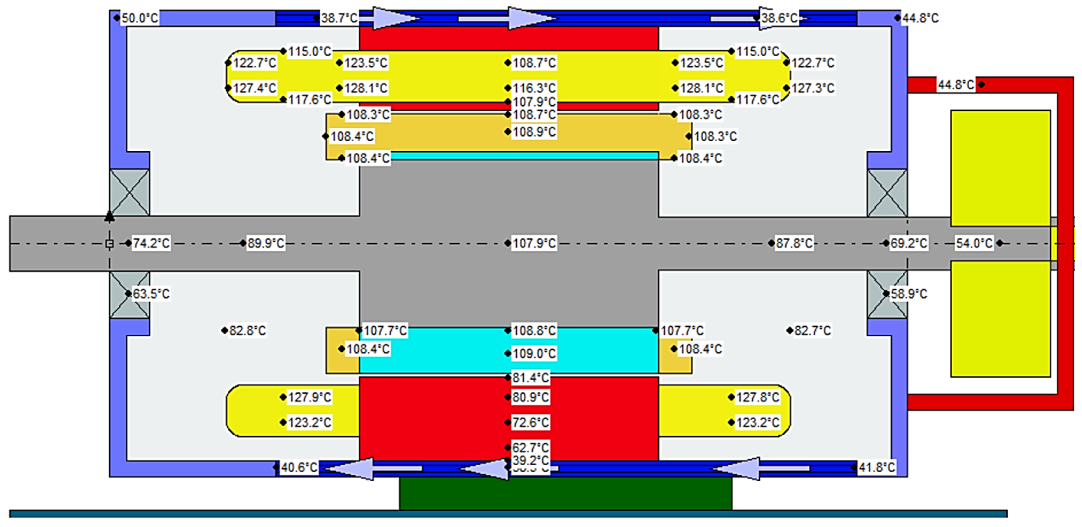
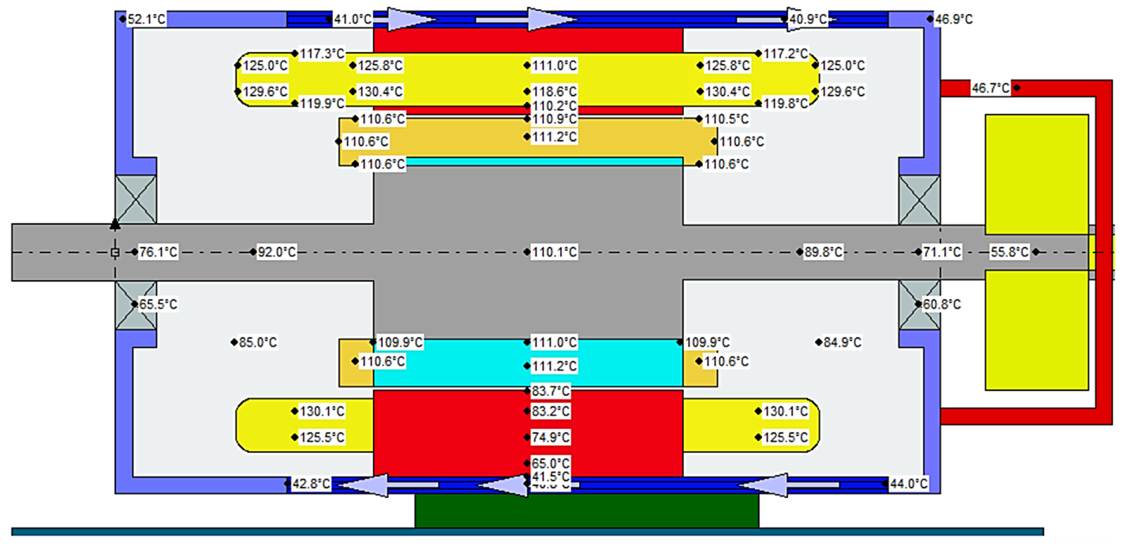
Figure 14 illustrates the variation of temperature at different parts of the induction motor when water was allowed to flow through housing jacket. Due to its large heat capacity, excellent thermal conductivity, and capability to absorb heat as it vaporises, water makes a great coolant. Water is utilised as a cooling medium in induction motors to remove heat produced by the continuous operation of the motor. Most often, a cooling jacket which encloses the motor is circulated with water. Conduction is the process by which heat from the motor is transferred to the water, which is then pumped off from the induction motor and into a heat exchanger or cooling tower where the heat is released into the air or another medium. The cooling procedure is then repeated when the water is returned to the motor.
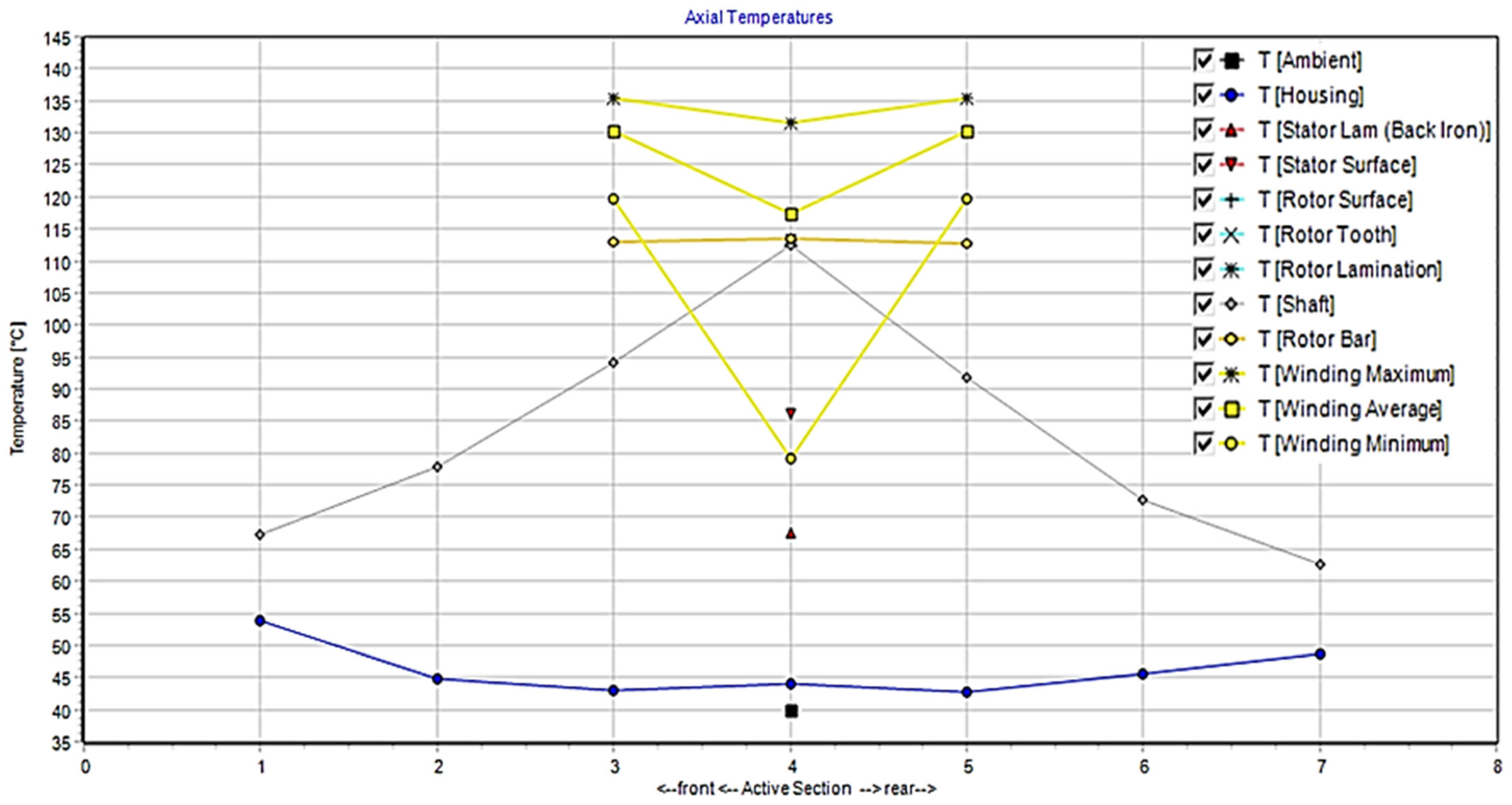
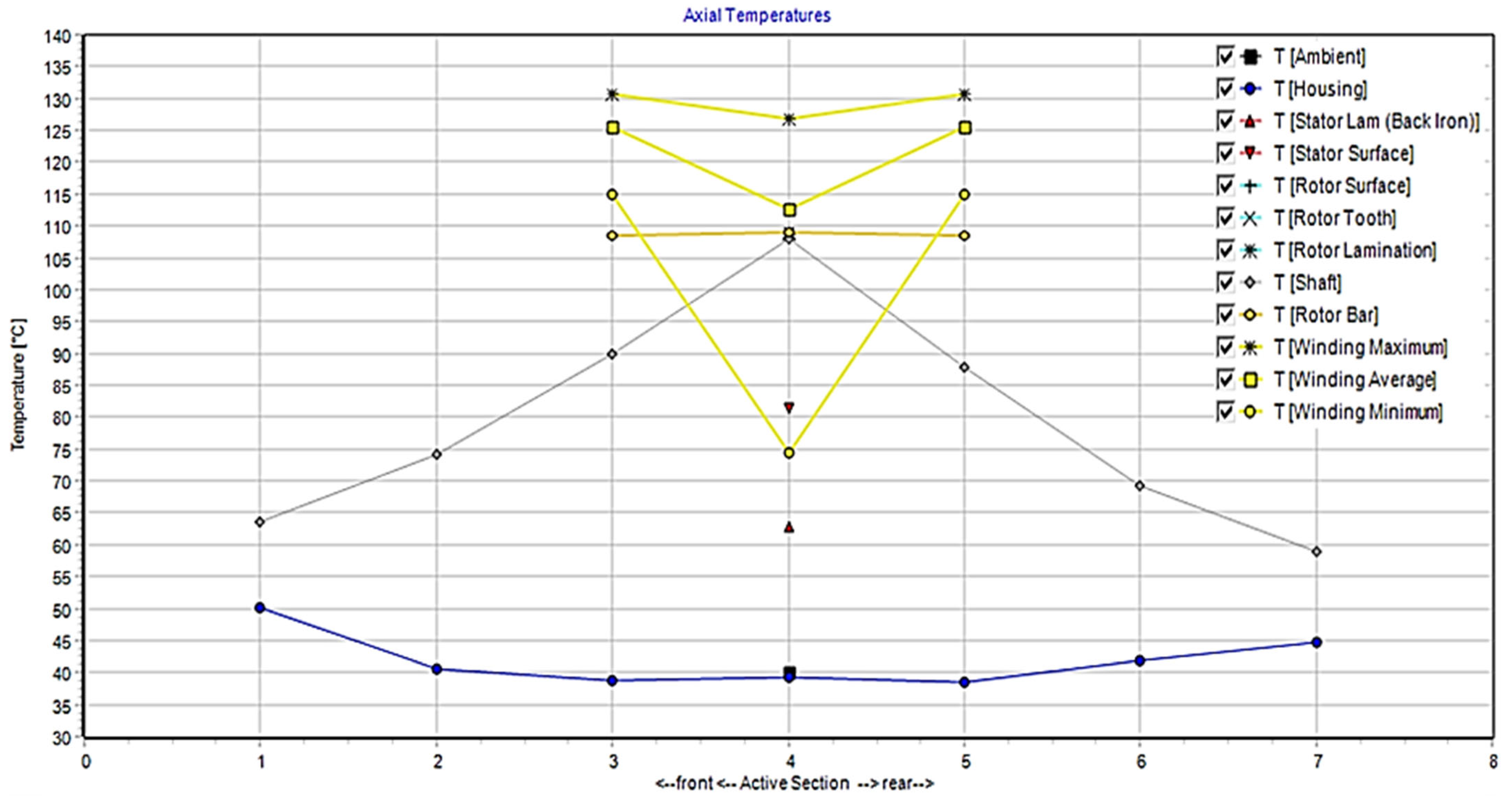
Figure 15 illustrates the variation of temperature at different parts of the induction motor when CuO was allowed to flow through the housing jacket. Induction motors have been demonstrated to operate more efficiently and at lower temperatures when coolants made of nanofluids such as CuO are used. The axial temperature profiles would serve as a useful tool for assessing how well the nanofluid cooled the motor and for refining the motor cooling systems design, as seen in Figure 15.
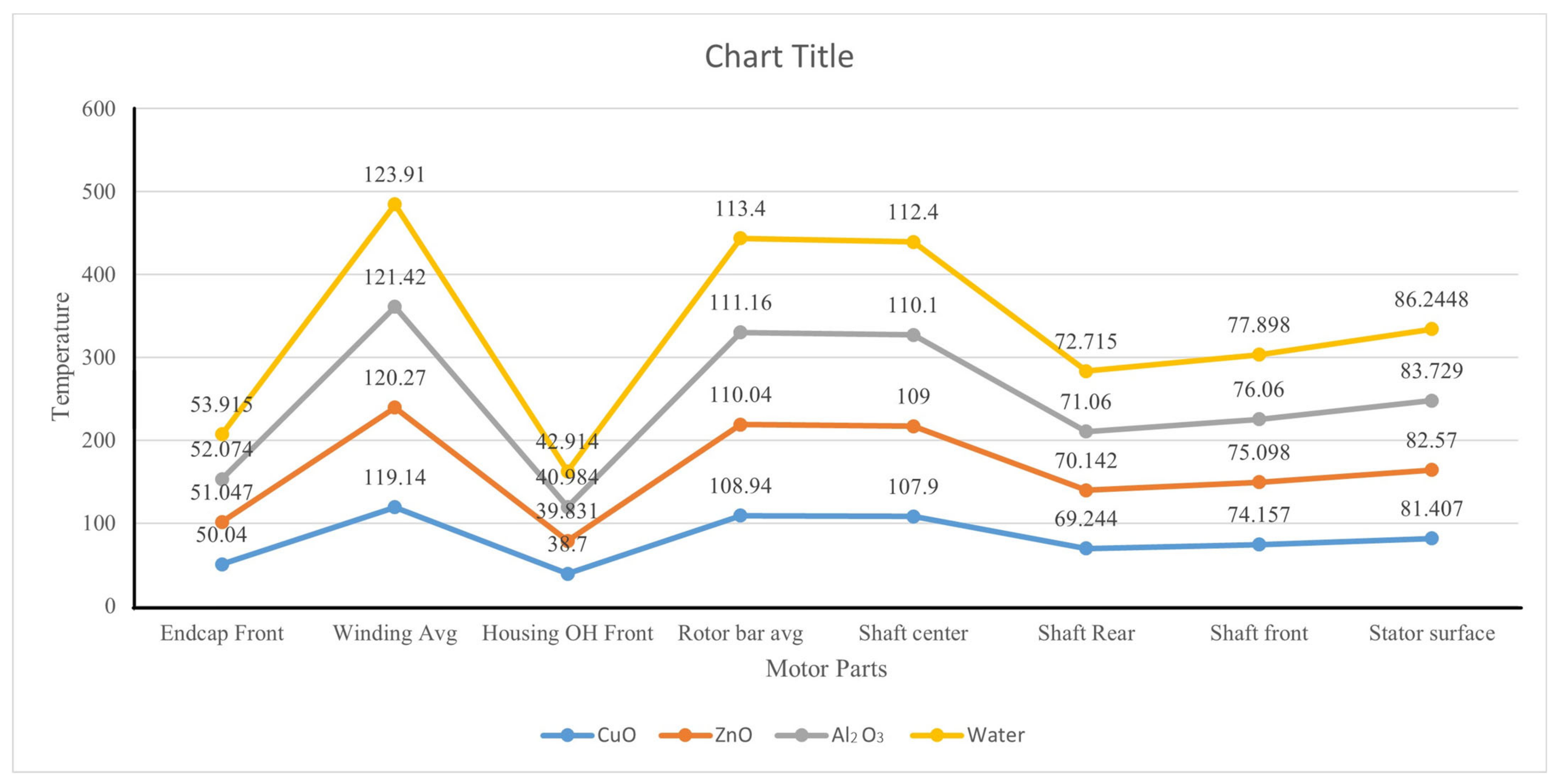
CuO was found to be a better coolant at every section as compared to water since the temperature at each part of the motor was significantly reduced while CuO was used. Additionally, the percentage of reduction was found maximum when CuO was used, followed by ZnO and then Al2O3. Hence, the surface area for heat transfer is further increased by the CuO (as compared to others, as seen in Figure 16) nanoparticles’ tiny size since they could fit into even the tiniest spaces between the motor’s parts.
The motor industry could gain from using a nanofluid as a coolant to lower motor temperatures in a number of ways, including the following:
Reduced Temperature: As motor temperature drops, its efficiency rises. The efficiency of a motor could be increased by using a nanofluid as a coolant to lower its temperature. Lower energy costs and more production may follow from this.
Extended Life: Motors are susceptible to wear and tear from high temperatures, which shortens their lives. The motor’s lifespan could be increased by lowering its temperature by employing a nanofluid as a coolant. As an effective coolant, nanofluid circulating around the motor absorbs the heat that it emits, thus extending its lifespan. This approach is frequently utilised in high-performance applications or in confined spaces since it is generally more effective than air cooling [27,28,29].
Lower maintenance Costs: When motors operate at high temperatures, maintenance is needed more frequently. Lower maintenance expenses could be achieved by using a nanofluid coolant to lower the motor’s temperature and, consequently, lessen the requirement for maintenance.
Enhanced Safety: Workers’ safety may be put at risk by motors operating at high temperatures. The danger of accidents could be lowered by utilising a nanofluid coolant to lower the motor temperature, making the workplace safer.

4. Conclusions

According to the experimental findings, using nanofluids could significantly decrease temperature rise and losses in various motor components. The following decreases in percentage of variation are seen when CuO-based nanofluid is used: a 7% decrease in the endcap (front) temperature, 10% decrease in the housing (front), 5% decrease in the shaft (rear) and shaft (front) temperature, a reduction of 4% in the maximum temperature, and a significant reduction of 9% in the minimum temperature (Table 7). These findings suggest that the introduction of nanofluids could enhance the induction motor’s cooling capability and general efficiency, making it a potential choice for high-performance electrical devices. The possible explanations for such findings are as follows:
CuO could transfer heat more effectively than conventional fluids due to its high thermal conductivity. The better thermal conductivity of nanofluids could aid in the swift and efficient dissipation of heat out of the motor, thereby reducing the likelihood of overheating and increasing the motor’s lifespan. Secondly, even if the motor is subjected to substantial loads or prolonged operation, a large specific heat capacity of CuO-based nanofluids helps to guarantee that the temperature of the motor stays steady and within the safe limits of operation.
CuO is a stable, non-toxic substance that is extensively used and reasonably priced. Because of this, it is an excellent option for use as motor cooling and other applications where effective heat transmission is crucial. Overall, it has been simulated and studied that CuO-based nanofluids work well as coolants for induction motors and other such applications where heat transmission is crucial. They are a desirable replacement for conventional coolants due to their excellent specific heat capacity, low toxicity, stability, and, especially, thermal conductivity.

Author Contributions

Conceptualization, G.K.P., S.S.S., E.G. and A.M.; methodology, G.K.P., E.G., A.M. and E.D.; validation, E.G., E.D., B.B.s. and A.M.; formal analysis, G.K.P., S.S.S., A.T., S.S.Y., S.S.T. and E.G.; investigation, G.K.P., S.S.S., E.G. and A.M.; resources, E.G., E.D. and A.M.; writing—original draft preparation, G.K.P., S.S.S., A.T., S.S.Y., B.B.s. and E.G.; writing—review and editing, G.K.P., B.B.s., E.G., E.D. and A.M.; visualization, E.D. and A.M.; supervision, E.G. All authors have read and agreed to the published version of the manuscript.

Funding

This research was funded by WZ/WE-IA/4/2023.

Institutional Review Board Statement

Not applicable.

Informed Consent Statement

Not applicable.

Data Availability Statement

Data may be shared with a reasonable request.

Acknowledgments

This research is supported by the Bialystok University of Technology project no WZ/WE-IA/4/2020 financed from a subsidy provided by the Ministry of Science and Higher Education and is supported by the Research Council of Lithuania and the Ministry of Education and Science of Ukraine under Lithuanian–Ukrainian Cooperation Programme in the Fields of Research and Technologies (Grant No.S-LU-22-6). The authors are thankful to the management of the Vellore Institute of Technology, India.

Conflicts of Interest

There was no specific grant for this research from organisations in the public, private, or non-profit sectors.

Nomenclature

QDissipated power density
T Temperature
λThermal conductivity
ρDensity
Tw Surface temperatures
T∞ Ambient cooling medium temperatures
α Heat transfer coefficient

References

  1. Madhavan, S.; PB, R.D.; Gundabattini, E.; Mystkowski, A. Thermal Analysis and Heat Management Strategies for an Induction Motor, a Review. Energies 2022, 15, 8127. [Google Scholar] [CrossRef]
  2. Boopathi, N.G.; Muthuraman, M.S.; Palka, R.; Wardach, M.; Prajzendanc, P.; Gundabattini, E.; Rassiah, R.S.; Solomon, D.G. Modeling and Simulation of Induction motors Using Lightweight Materials. Energies 2022, 15, 5183. [Google Scholar] [CrossRef]
  3. Gundabattini, E.; Mystkowski, A.; Raja Singh, R.; Gnanaraj, S.D. Water cooling, PSG, PCM, Cryogenic cooling strategies and thermal analysis (experimental and analytical) of a Permanent Magnet Synchronous Motor: A review. Sādhanā 2021, 46, 124. [Google Scholar] [CrossRef]
  4. Cavazzuti, M.; Gaspari, G.; Pasquale, S.; Stalio, E. Thermal management of a Formula E induction motor: Analysis and optimization. Appl. Therm. Eng. 2019, 157, 113733. [Google Scholar] [CrossRef]
  5. Rehman, Z.; Seong, K. Three-D numerical thermal analysis of induction motor with cooling jacket. Energies 2018, 11, 92. [Google Scholar] [CrossRef]
  6. Rajagopal, M.; Seetharamu, K.; Ashwathnarayana, P. Transient thermal analysis of induction motors. IEEE Trans. Energy Convers. 1998, 13, 62–69. [Google Scholar] [CrossRef]
  7. Carriero, A.; Locatelli, M.; Ramakrishnan, K.; Mastinu, G.; Gobbi, M. A Review of the State of the Art of Electric Traction Motors Cooling Techniques; SAE Technical Paper 2018-01-0057; SAE International: Warrendale, PA, USA, 2018. [Google Scholar] [CrossRef]
  8. Fujita, H.; Itoh, A.; Urano, T. Newly developed motor cooling method using refrigerant. World Electr. Veh. J. 2019, 10, 38. [Google Scholar] [CrossRef]
  9. Davin, T.; Pellé, J.; Harmand, S.; Yu, R. Experimental study of oil cooling systems for induction motors. Appl. Therm. Eng. 2015, 75, 1–13. [Google Scholar] [CrossRef]
  10. Guo, F.; Zhang, C. Oil-cooling method of the permanent magnet synchronous motor for electric vehicle. Energies 2019, 12, 2984. [Google Scholar] [CrossRef]
  11. Ha, T.; Kim, D.K. Study of Injection Method for Maximizing Oil-Cooling Performance of Electric Vehicle Motor with Hairpin Winding. Energies 2021, 14, 747. [Google Scholar] [CrossRef]
  12. Naini, S.S.; Huang, J.A.; Miller, R.; Wagner, J.R.; Rizzo, D.; Sebeck, K.; Shurin, S. An Innovative Induction Motor Cooling System for Hybrid Vehicles-Model and Test; SAE Technical Paper 2019-01-1076; SAE International: Warrendale, PA, USA, 2019. [Google Scholar] [CrossRef]
  13. Gundabattini, E.; Kuppan, R.; Solomon, D.G.; Kalam, A.; Kothari, D.P.; Bakar, R.A. A review on methods of finding losses and cooling methods to increase efficiency of electric machines. Ain Shams Eng. J. 2021, 12, 497–505. [Google Scholar] [CrossRef]
  14. McCluskey, F.P.; Saadon, Y.; Yao, Z.; Camacho, A. Cooling for electric aircraft motors. In Proceedings of the 2019 18th IEEE Intersociety Conference on Thermal and Thermomechanical Phenomena in Electronic Systems (ITherm), Las Vegas, NV, USA, 28–31 May 2019; pp. 1134–1138. [Google Scholar] [CrossRef]
  15. Gundabattini, E.; Mystkowski, A.; Idzkowski, A.; Solomon, D.G. Thermal mapping of a high-speed induction motor used for traction applications and analysis of various cooling methods—A review. Energies 2021, 14, 1472. [Google Scholar] [CrossRef]
  16. Hamilton, R.L.; Crosser, O.K. Thermal Conductivity of Heterogeneous Two-Component Systems. Ind. Eng. Chem. Fundam. 1962, 1, 187–191. [Google Scholar] [CrossRef]
  17. Pak, B.C.; Cho, Y.I. Hydrodynamic and Heat Transfer Study of Dispersed Fluids with Submicron Metallic Oxide Particles. Exp. Heat Transf. 1998, 11, 151–170. [Google Scholar] [CrossRef]
  18. Einstein, A. Eine Neue Bestimmung der Moleküldimensionen. Ph.D. Thesis, ETH Zurich, Zürich, Switzerland, 1905. [Google Scholar]
  19. Abdullah, A.T.; Ali, A.M. Thermal analysis of a three-phase induction motor based on motor-CAD, flux2D, and matlab. Indones. J. Electr. Eng. Comput. Sci. 2019, 15, 46–53. [Google Scholar] [CrossRef]
  20. Grabowski, M.; Urbaniec, K.; Wernik, J.; Wołosz, K.J. Numerical simulation and experimental verification of heat transfer from a finned housing of an induction motor. Energy Convers. Manag. 2016, 125, 91–96. [Google Scholar] [CrossRef]
  21. Venturini, G.; Volpe, G.; Popescu, M. Slot Water Jacket Cooling System for Traction Electrical Machines with Hairpin Windings: Analysis and Comparison. In Proceedings of the 2021 IEEE International Electric Machines & Drives Conference (IEMDC), Hartford, CT, USA, 17–20 May 2021. [Google Scholar] [CrossRef]
  22. Vajjha, R.S.; Das, D.K. A review and analysis on influence of temperature and concentration of nanofluids on thermophysical properties, heat transfer and pumping power. Int. J. Heat Mass Transf. 2012, 55, 4063–4078. [Google Scholar] [CrossRef]
  23. Ponmani, S.; William, J.K.M.; Samuel, R.; Nagarajan, R.; Sangwai, J.S. Formation and characterization of thermal and electrical properties of CuO and ZnO nanofluids in xanthan gum. Colloids Surf. A Physicochem. Eng. Asp. 2014, 443, 37–43. [Google Scholar] [CrossRef]
  24. Mezani, S.; Takorabet, N.; Laporte, B. A combined electromagnetic and thermal analysis of induction motors. IEEE Trans. Magn. 2005, 41, 1572–1575. [Google Scholar] [CrossRef]
  25. Lyu, Y.; Siddique, A.R.M.; Majid, S.H.; Biglarbegian, M.; Gadsden, S.A.; Mahmud, S. Electric vehicle battery thermal management system with thermoelectric cooling. Energy Rep. 2019, 5, 822–827. [Google Scholar] [CrossRef]
  26. Mopidevi, S.; Narasipuram, R.P.; Aemalla, S.R.; Rajan, H. E-mobility: Impacts and analysis of future transportation electrification market in economic, renewable energy and infrastructure perspective. Int. J. Powertrains 2022, 11, 264–284. [Google Scholar] [CrossRef]
  27. Chen, Y. Research on collaborative innovation of key common technologies in new energy vehicle industry based on digital twin technology. Energy Rep. 2022, 8, 15399–15407. [Google Scholar] [CrossRef]
  28. Pauliukaitis, D.; Gegeckienė, L.; Venytė, I.; Kibirkštis, E. Research on a single-chamber pneumatic vibroactuator. Mechanics 2023, 29, 162–167. [Google Scholar] [CrossRef]
  29. Yao, Z.; Yoon, H. Control Strategy for Hybrid Electric Vehicle Based on Online Driving Pattern Classification. SAE Int. J. Altern. Powertrains 2019, 8, 91–102. [Google Scholar] [CrossRef]
Figure 1. Front view of a typical AC Induction motor [2].
Sustainability 15 08124 g001
Figure 2. High temperature effect on motor parts.
Sustainability 15 08124 g002
Figure 3. Flow chart of conducting the simulations and analysis.
Sustainability 15 08124 g003
Figure 4. Radial view of analysed motor.
Sustainability 15 08124 g004
Figure 5. Axial view of analysed motor.
Sustainability 15 08124 g005
Figure 6. Comparing density of three different nanofluids.
Sustainability 15 08124 g006
Figure 7. Comparing kinematic viscosity of three different nanofluids.
Sustainability 15 08124 g007
Figure 8. Comparing thermal conductivity of three different nanofluids.
Sustainability 15 08124 g008
Figure 9. Comparing specific heat capacity of three different nanofluids.
Sustainability 15 08124 g009
Figure 10. Temperature distribution at each section of the motor when water is used.
Sustainability 15 08124 g010
Figure 11. Temperature distribution at each section of the motor when CuO-based nanofluid is used.
Sustainability 15 08124 g011
Figure 12. Temperature distribution at each section of the motor when ZnO-based nanofluid is used.
Sustainability 15 08124 g012
Figure 13. Temperature distribution at each section of the motor when Al2O3-based nanofluid is used.
Sustainability 15 08124 g013
Figure 14. Variation in axial temperature at different sections of the motor for water-cooled motor.
Sustainability 15 08124 g014
Figure 15. Variation in axial temperature at different sections of the motor for CuO-based nanofluid cooled motor.
Sustainability 15 08124 g015
Figure 16. Comparison between the water and nanofluids—temperature at various sections of the motor.
Sustainability 15 08124 g016
Table 1. Properties of nanoparticle used.
PropertyAl2O3ZnOCuO
Molecular weight (g/mol)101.9681.3879.545
Size (mm)35–4530–4030–50
Thermal conductivity (W/m.K)404932.9
Density (kg/m3)1293.1391462.1391527.139
Heat capacity (J/kg·K)3739.683712.584035.18
Viscosity (kg/m.s)2.52519 × 10−101.7712 × 10−101.58875 × 10⁻¹⁰
Table 2. Induction motor condition.
Section/Part of the MotorSpecific PartDimensions (mm)
Radial dimensionsHousing diameter140
Diameter of the stator lamination130
Diameter of the shaft50
Height of the shaft95
Axial dimensionsMotor length240
Length of the stator lamination50
Length of the rotor lamination90
Base length350
Stator parametersHousing diameter140
Tooth width71
Rotor parametersWidth of the rotor tooth4
Diameter of the Shaft50
Table 3. Specifications of the single-phase induction motor.
ParametersValues
Output rated power373 W (0.5 HP)
Voltage (rated)230V
Speed (rated)1430 rpm
Frequency50 Hz
Additional motor specifications: Motor type—Split capacitor (Permanent); Insulation type—Class F; Encloser Type—DPFC (Distributed Power Flow Controller; Number of Poles: 4; Number of Stator slots: 24; Number of rotor bars: 26).
Table 4. Input parameters for thermal analysis on ANSYS Motor-CAD.
Input ParameterInput Data
HousingWater jacket (axial)
Housing materialAluminium (alloy 195 cast), thermal conductivity—168 W/m/C, specific heat—833 J/kg/C
Calculation typeSteady-state thermal analysis
Input power750 W
Shaft speed2880 rpm
Table 5. Fluid properties.
Input ParameterInput Data
Fluid volume flow rate1 L/min
Inlet temperature30 °C
Parallel flow paths1
Table 6. Percentage of reduction in temperature at various parts of the motor.
PartsTemperature (°C)Percentage of Reduction
WaterAl2O3-Based NanofluidCuO-Based NanofluidZnO-Based NanofluidAl2O3-Based NanofluidCuO-Based NanofluidZnO-Based Nanofluid
Endcap front53.91552.07450.0451.0473%7%5%
Winding avg.123.91121.42119.14120.272%4%3%
Housing OH front42.91440.98438.739.8314%10%7%
Rotor bar avg.113.4111.16108.94110.042%4%3%
Shaft centre112.4110.1107.91092%4%3%
Shaft rear72.71571.0669.24470.1422%5%4%
Shaft front77.89876.0674.15775.0982%5%4%
Stator surface86.244883.72981.40782.573%6%4%
Table 7. Comparison of temperature at motor parts using water cooling for different materials.
PartsTemperature (°C)Percentage Difference (in Temperature)
PA6GF30 30% GPFR (Glass Fibre-Reinforced Polymer) [20]Aluminium (Alloy 195 Cast)
Shaft centre104.5112.47.23
Shaft rear75.572.7153.76
Shaft front84.977.8988.60
Stator surface69.486.244821.65
Rotor bar avg.105.2113.47.50
Winding avg.107.5123.9114.18
Table 8. Percentage of reduction in ambient, maximum, and minimum temperature.
AreaTemperature (°C)Percentage of Reduction
WaterAl2O3-Based NanofluidCuO-Based NanofluidZnO-Based NanofluidAl2O3-Based NanofluidCuO-Based NanofluidZnO-Based Nanofluid
Ambient40404040---
Maximum132.9130.4128.1129.22%4%3%
Minimum42.540.838.539.64%9%7%
Disclaimer/Publisher’s Note: The statements, opinions and data contained in all publications are solely those of the individual author(s) and contributor(s) and not of MDPI and/or the editor(s). MDPI and/or the editor(s) disclaim responsibility for any injury to people or property resulting from any ideas, methods, instructions or products referred to in the content.

