Method for Characterization of a Multirotor UAV Electric Propulsion System


1
Department of Technology, Faculty of Mechanical Engineering and Naval Architecture, University of Zagreb, 10000 Zagreb, Croatia
2
Department of Mechanical Engineering, Karlovac University of Applied Sciences, 47000 Karlovac, Croatia
3
Department of Robotics and Production System Automation, Faculty of Mechanical Engineering and Naval Architecture, University of Zagreb, 10000 Zagreb, Croatia
*
Author to whom correspondence should be addressed.
Appl. Sci. 2020, 10(22), 8229; https://0-doi-org.brum.beds.ac.uk/10.3390/app10228229
Submission received: 16 October 2020
/
Revised: 18 November 2020
/
Accepted: 18 November 2020
/
Published: 20 November 2020
(This article belongs to the Section Aerospace Science and Engineering)
Abstract
:Due to their abilities, multirotor unmanned aerial vehicles (UAVs) can be used in various missions that require complex and precise movements, so they are a typical representative of aerial robots. Since this type of UAV is characterized by high energy consumption, it is of most importance to precisely choose the system parameters and components in order to achieve the required flight performance that meets the mission requirements. In this paper, a method for characterization of the multirotor UAV propulsion system is proposed, which is a fundamental step in the design process of this type of UAV. For the purpose of method validation, experimental measurements and signal acquisition were performed, and the measurement results for the considered electric propulsion units were shown. An identification procedure is presented, which is used to process the measurement results or manufacturer’s data and display them as propulsion unit static maps. Based on static maps, the characterization process of the electric propulsion system is performed, and the propulsion unit characteristics are shown.
1. Introduction
In the last 10 years, research in the field of unmanned aerial vehicles (UAVs) has experienced a vast expansion, which is made possible by the development of aircraft components, primarily micro-electromechanical systems (MEMS) sensors, microcontrollers, batteries, and propulsion components. There are several categories of UAVs that are in different stages of research, development, and utilization. Depending on the categories and purpose, the UAVs are designed from the size of a fighter aircraft (unmanned combat aerial vehicle, UCAV), down to micro aerial vehicles (MAVs) [1]. Multirotor types of UAVs have the capability of vertical take-off and landing, remain stationary in the air (hover), and flight at a moderate speed allowing them to conduct complex maneuvers which makes them suitable for a wide range of tasks. Different multirotor configurations are intended for missions such as surveillance [2], inspection [3], applications in the construction management [4], agriculture [5], search and rescue missions [6], manipulation and interaction with the environment [7], and others. Conventional configurations are characterized by parallel (planar) and symmetrical arrangement of an even number of rotors, most commonly realized as quadrotor (quadcopter) [8], hexarotor (hexacopter) [9], or octorotor (octocopter) [10].
In the multirotor UAV design process, the requirements of the mission or task as part of the mission need to be considered. The main criterion of multirotor design is the required performance that aircraft should be able to achieve during the flight mission. Given that the propulsion system should provide the thrust required for the movement of the aircraft, respectively achieve the required flight performance, the selection of parameters and components of the propulsion system is the most important and complex step. The configuration parameters, i.e., the geometric arrangement of the propulsion system determines the distribution of the propulsion units generated forces and moments to the control forces and moments of the propulsion system. Since it is possible to achieve the full degree of controllability of the system by selecting the particular configuration parameters [11], multirotor UAVs are a typical representative of aerial robots due to the possibility of performing precise and complex movements. The dynamics, as well as energy consumption, directly depend on the selected components and the number of propulsion units. It turns out that the propulsion and energy systems are interdependent and when choosing components, it is necessary to maintain a balance with the existing constraints defined by the mission.
Most commonly, the multirotor propulsion system consists of pure electric propulsion (i.e., electric motors fitted with an appropriate propeller and powered by an electrochemical battery). Numerous papers have investigated and presented ways to identify the parameters of multirotor propulsion units [12,13]. Regardless of the propulsion type, the physical parameters on the one hand represent the aerodynamic forces and moments generated by the propulsion unit while on the other hand, there are the parameters of energy consumption. In [14,15], experimental setups for the identification of parameters are presented, and there are also test stands available on electric propulsion unit (EPU) market [16]. In addition to experimental identification, research has been conducted with the aim of a more detailed and accurate mathematical description of the rotor [17]. The efficiency of the propulsion configurations of aircraft with an overlap of propulsion surfaces was also investigated since such rotor arrangements are characterized by a loss of the total thrust force [18]. Additionally, in [19,20] the relation of energy consumption and flight time (autonomy) are considered.
In this paper, a method for characterization of the electric propulsion system is proposed, which is an important step in the multirotor UAV design process. The method was validated using experimental measurements of various EPU setups. The parameter identification procedure is presented which, based on experimental measurements data or manufacturer’s data, results in EPU static maps. Such static maps exactly show the physical parameters in relation to the control (PWM) signal and characterize EPU. The characteristics show aerodynamic forces and moments with respect to rotor angular velocity as well as energy consumption and overall efficiency measure. The proposed characterization method without significant modifications can be applied to the full power range of EPUs, from a few watts to a few tenths of kilowatts which can further lead to parameter estimation, system analysis, and optimization.
2. Preliminary Description of a Multirotor UAV
The mathematical description is an approximation and abstraction of a real system and, in this case, multirotor UAV is viewed as a rigid body that exists in three-dimensional space, so it has six degrees of freedom (DOF). Propellers with a fixed pitch angle are mounted on the motor shaft and they are the only moving parts, which means that the dynamics of this type of UAV directly depend on the rotor angular velocities. The stiffness of the propeller and the symmetry of the aircraft configuration are assumed. Multirotor UAV performance depends on the selected configuration and the propulsion components.
2.1. Multirotor UAV Dynamics
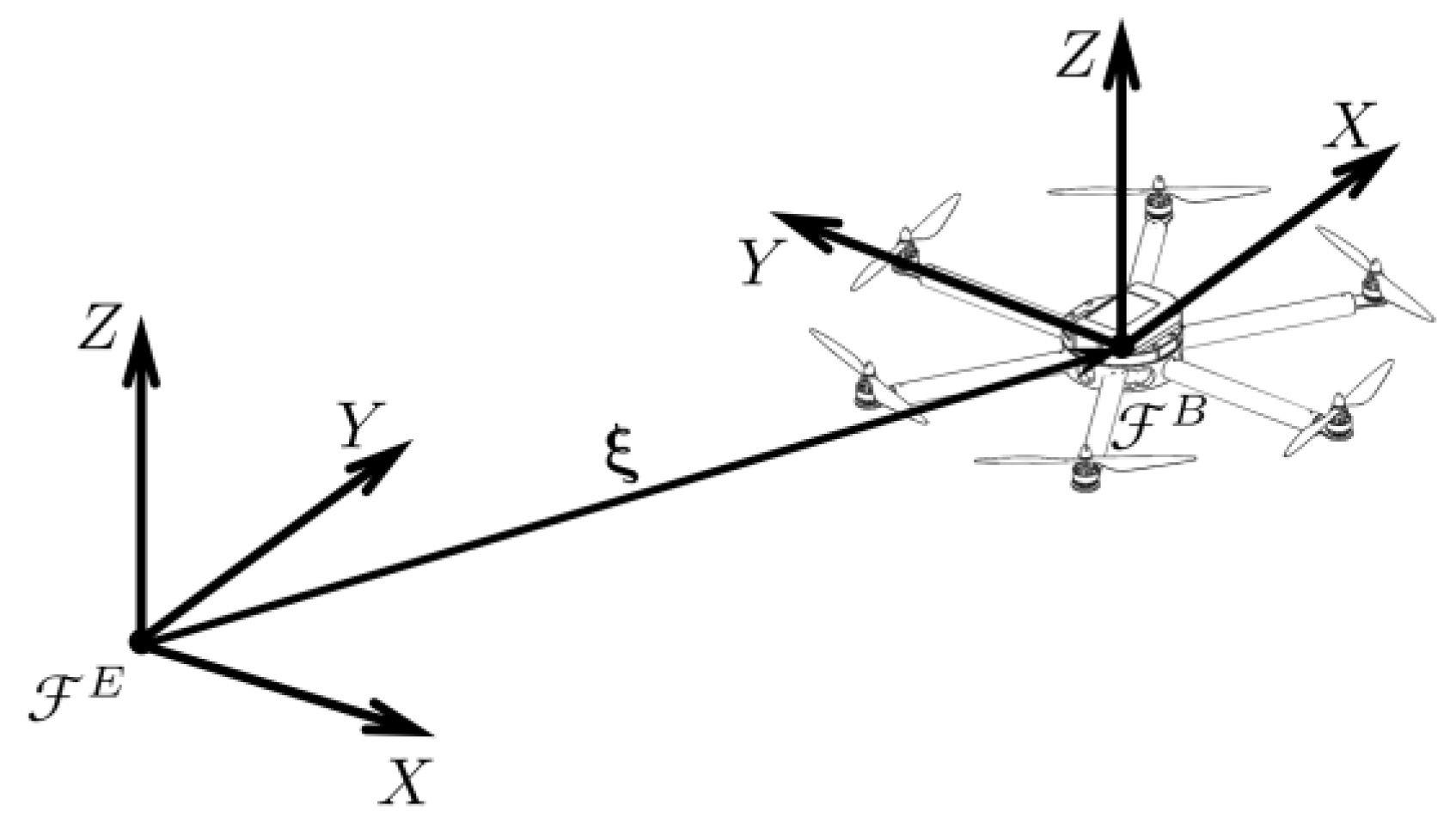
To describe the multirotor kinematics and dynamics, two right-handed Cartesian coordinate systems are defined as follows. Inertial coordinate system (called Earth frame, ) is fixed to the considered stationary point on the Earth surface, where Z axis coincides with the normal and positive direction is defined upwards from the ground level. Aircraft coordinate system (called Body frame, ) is fixed to the moving multirotor where the origin coincides with the center of gravity (COG), and axes coincide with the multirotor main axes of inertia. Multirotor position is determined by the vector which connects the origin of with the origin of (see Figure 1). Multirotor orientation (attitude) is determined by a vector consisting of three Euler angles,
. Rotation around the longitudinal axis () is defined as roll angle , while rotation around the lateral axis () as pitch angle , and rotation around the vertical axis () as yaw angle . The multirotor translational and rotational velocity vectors are defined in in which the equations of motion are described.
Assuming that the multirotor is a rigid body, translational and rotational motion can be described as the motion of a particle located at the center of gravity of the body. The kinematics of a rigid body describes the mapping of the translational and rotational velocities from to . It is defined by the following expression
where is the rotation matrix that maps the translational velocities, is the zero matrix, and is the transformation matrix that maps rotational velocities. According to Euler’s orientation theorem, the transformation from to is described by three consecutive rotations and the final orthogonal rotation matrix can be defined as
where . By resolving Euler angle rates, the transformation matrix is defined as
The multirotor equations of motion are based on the Newton–Euler approach where a system of six second-order differential equations is obtained. The equations of translational motion in are defined by the following expression
where is the mass of the multirotor system, and is the vector of forces acting on the body with respect to , .
The equations of rotational motion in are defined by the following expression
where is the body’s inertia matrix which is time-invariant in and is the vector of moments acting on the body with respect to , .
The multirotor dynamic is influenced by external forces and moments caused by the forces and moments of the propulsion system and environment. The force vector is equal to
where is the vector of the gravitational force, is the force vector of external disturbances and unmodeled dynamics, and is the propulsion system force vector. The moment vector is equal to
where is the gyroscopic moment vector, is the moment vector of external disturbances and unmodeled dynamics, and is the propulsion system moment vector.
Propulsion system forces and moments vector (called control vector) is defined as . The control vector directly influences the system dynamics and it can also be defined as
where is the matrix of the control allocation scheme and control forces and moments are modeled as proportional to the square of the propeller’s angular velocities, .
2.2. Multirotor UAV Propulsion System
A common feature of all multirotor design variants is that they consist of N propulsion units (rotors). The multirotor performance is affected by the geometric arrangement and power of the propulsion units. Conventional multirotor configurations (so-called planar configurations) consist of an even number of propulsion units symmetrically arranged in one or more parallel planes. Additionally, half of the rotors turn in a clockwise (CW) direction, while the other half turns counterclockwise (CCW) in order to cancel the reactive moment around . There are also configurations with the nonplanar geometric arrangement, where it is possible to achieve a full actuation of multirotor [21].
The propulsion system configuration is defined with a control allocation scheme that describes the mapping of the rotor angular velocities to the multirotor control vector. The rows of the control allocation matrix,
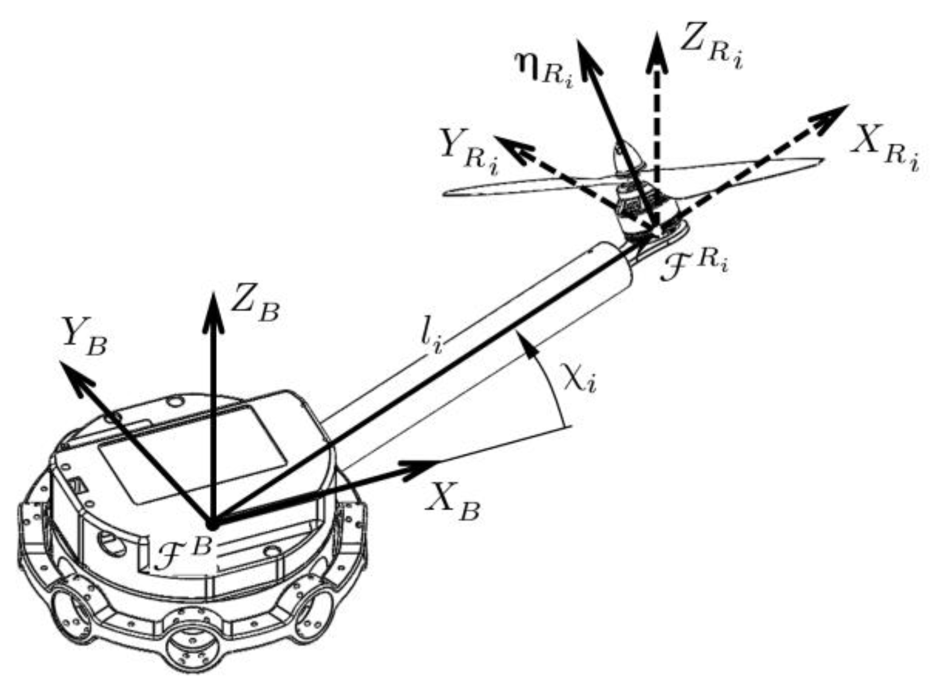
represent the degrees of freedom of motion, while the columns represent the rotors (propulsion units). Propulsion units are defined by two characteristic aerodynamics factors: thrust force () and drag torque (). The geometric arrangement of each rotor (see Figure 2) is defined by the position and orientation .
The position vector of the i-th rotor is given by the following expression
where is the position angle of the i-th rotor defined in the horizontal plane of the aircraft (), and is the length of the i-th rotor arm. The orientation vector of the i-th rotor is given by the following expression
where is the cant angle of the i-th rotor, is the tilt angle of the i-th rotor, and is a unit vector since the considered aerodynamic effects are represented in the rotor vertical axis.
In order to separate the parameters of the geometric arrangement and the parameters of the propulsion units, a decomposition of the control allocation matrix is given as
Multirotor configuration geometric arrangement is represented with and . The propulsion unit parameters are represented by a diagonal matrix of rotor thrust force factors
and a diagonal matrix of the rotor drag torque factors
The sign of the drag torque factor depends on the direction of rotation of the rotor, CW rotors have a positive sign, while CCW rotors have a negative sign.
2.3. EPU Components
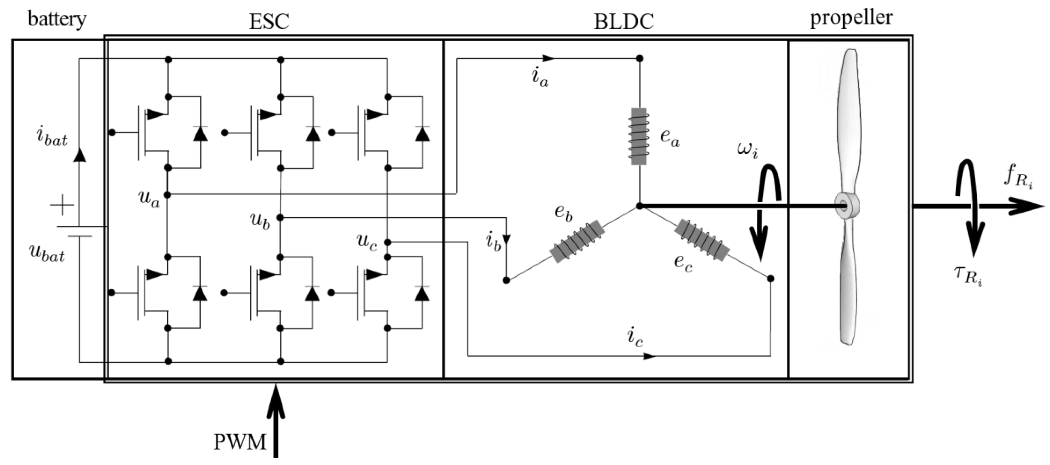
The EPU must enable precise and fast control of forces and moments that directly affect the position and orientation of the aircraft. The reliability of modern electrical systems reduces the possibility of aircraft crash due to motor failure. Conventional EPU consist of a brushless DC (BLDC) motor and associated electronic speed controller (ESC), with a fixed pitch propeller mounted to the motor shaft. In general, EPU is suitable for a vast range of applications due to the wide choice of commercially available components (i.e., ESCs and motors of different power, size, and appropriate propellers). Figure 3 schematically shows a conventional EPU.
2.3.1. Fixed Pitch Propeller
By rotation of propellers, the aerodynamic forces and moments are generated, and directly affect the dynamics of the multirotor. It is assumed that the aerodynamic forces and moments consist of the thrust force and the drag torque, while the other components are neglected. In the case of fixed pitch propellers, the required aerodynamic forces, and torques are achieved by changing the angular velocity, i.e., the RPM of the rotor. They are made mainly of plastic, carbon composites, or wood.
The basic parameters of the propeller geometry required for the physical description of the EPU are the diameter and pitch angle of the propeller. Increasing the diameter or pitch angle or even the number of propeller blades results in a larger amount of induced airflow and respectively greater thrust force. On the other hand, the consequence is greater resistance to rotation, which is manifested in motor torque increase, i.e., an increase in power consumption. The thrust force of the i-th rotor is defined by the following expression
where is the thrust force factor, and is the angular velocity of the i-th rotor. Thrust force factor, expressed in , depends on the geometry of the propeller and the air density , and is defined by the following expression
where is the propeller thrust coefficient, is the propeller disk surface, and is the radius.
2.3.2. BLDC Motor
BLDC motor is a permanent magnet electric motor with an electronic commutation system. It is driven by a rectangular shape input voltage (six-step commutation) provided by an ESC. Electromagnets (armature) are located on the stator of the motor, while permanent magnets are located on the rotor. Compared to conventional DC motors that use mechanical commutation (brushes), BLDC motors have higher efficiency, increased reliability, higher torque by weight, reduced noise, and easier maintenance. There are two basic types of BLDC rotor design realization. In the first type, the rotor is positioned inside the stator (inrunner), while in the second type (commonly used in multirotors) the rotor is positioned outside the stator (outrunner). There is a large range of commercially available BLDC motors with output power from tens of W up to several kW. The recommended propeller size and operating voltage range are given by the manufacturer in the form of tabular specification of combined motor and propeller performance (i.e., voltage and current consumption at obtained thrust). Load on the i-th motor is imposed by drag torque of the i-th rotor and can be expressed as
where is the drag torque factor of the i-th rotor (Nms2). It depends on the geometry of the propeller, the air density, and the motor power, and it is defined by the following expression
where is the rotor power coefficient.
The motor configuration defines the number of stator and rotor poles, for example, a 12N14P configuration consists of 12 stator poles and 14 rotor poles. Motor velocity constant (back EMF constant) defines the number of revolutions per applied voltage in the case with no load (propeller is not mounted on the motor rotor),
BLDC motors of small dimensions and large velocity constants () are mainly used to propel micro and small aircraft intended for entertainment or sports (drone racing). On the other hand, medium-sized BLDC motors with medium velocity constants () are used to propel aircraft intended for photography or similar tasks where cargo masses are up to . Finally, large BLDC motors with small velocity constants () are intended for heavy equipment and loads and are also considered for personal aerial vehicles (PAV) propulsion, the introduction of which is planned for the next decade [22].
2.3.3. ESC
ESC is an integrated power inverter that converts supplied DC voltage into appropriate AC phase voltages to drive the motor. The ESC consists of a microcontroller that processes (interprets) the input PWM signal and switching transistors (most commonly MOS-FET). The switching sequence of the transistors is determined by commutation and depends on the position of the rotor, which can be determined using a sensor or sensorless method [23].
In other words, ESC implements the proper sequence to energize particular phases of a motor, in order to achieve continuous rotation and thus desired RPM set by the input signal from the flight controller. The digital input signal (throttle) defines the switching rate of transistors and consequently voltage fed to phases. With a higher duty cycle of the PWM, the phase voltage is increased and thus the angular velocity of the motor.
The main parameter for selecting the ESC is the maximum allowed current of the controller and the operating voltages expressed in the number of battery cells. The maximum allowable current must be 20–50% higher than the maximum motor current to avoid overheating or failure. The factory settings can be changed using the ESC programmer, such as the possibility of dynamic braking. Recently, several communication protocols have been developed between the ESC and the flight controller (Oneshot, Multishot, and Dshot) that offer certain advantages over the PWM signal, such as faster communication.
3. EPU Parameters Identification Procedure
Identification of EPU physical parameters is the basis for the characterization of EPU and it is required for the study of propulsion and power source systems. For this purpose, experimental measurements were conducted. The heaviest and most expensive component of EPU is the BLDC motor, which affects the selection of other propulsion components (propeller and ESC). Therefore, it was chosen as the starting point of this study. Additionally, the selection of EPU components must be accompanied by a properly selected energy source, i.e., a battery that poses required voltage and capacity. Table 1 shows the components used in experimental measurements. Based on the measurement results, identification of the EPU parameters was done and EPU static maps were generated as shown in the following subsections. EPU static maps are then used in the next section to perform the characterization of each EPU and characterization of the entire electric propulsion system.
3.1. Experimental Setup
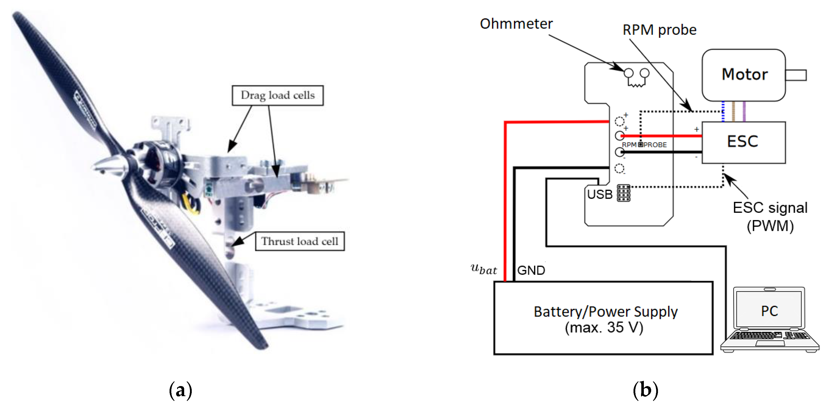
For the purposes of experimental measurements, it is necessary to select measuring equipment that has sufficient accuracy, resolution, and compatibility with the appropriate software package for data acquisition. There are several established setups [24] and commercially available measurement systems such as RCbenchmark 1580 [16] (see Figure 4) which was used in this research. Measurement of mechanical quantities, i.e., aerodynamic forces () and moments (), takes place using a dynamometer consisting of three load cell sensors. The rotor RPM was measured electrically by a measuring probe that was connected to a single motor phase, and optically through an optical sensor that counts revolutions by detecting a marker mounted on the motor. From electrical quantities, battery voltage (), electric current (), and electric power () were measured. In addition to the mentioned mechanical and electrical quantities, the motor temperature can be monitored by utilizing an additional temperature sensor. Furthermore, the vibrations of propellers were measured by an accelerometer (embedded within test stand), and it was checked whether their intensity is below the limit that would significantly affect the results. In the case of unfavorable vibrations, or if measured values exceed the defined limit values, the software reports an error and stops the measurement process (safety cutoff) to protect equipment from damage. Additionally, in order to validate the setup, it is important to check if correct RPM is obtained (i.e., with optical rpm probe), and additionally check the validity of electrical measurements by a multifunction logger.
Load cell sensors were used to measure thrust and drag from the propeller. The first sensor with a range of up to 5 kg, is located vertically on the setup and used to measure the thrust of the EPU (Figure 4a). The base with mounted EPU is attached to the left and right load cell sensors, that are used to measure the drag torque. The strain gauges of load cells are connected to signal amplifiers that are 24-bit analog-to-digital converters (ADCs) integrated into a data acquisition board. According to the diagram in Figure 4b, ESC, other sensors, and power supply were connected to the setup control board, which connects the PC via USB cable. Prior to the measurements, the dynamometer was calibrated according to the procedure described in the installation documentation [16]. To verify the measurement of electrical quantities and angular velocity of the rotor, a multifunctional logger PowerLog 6S [25] was used. Signal acquisition and data storage in .csv format was performed in the software package that comes with the setup.
3.2. Data Acquisition
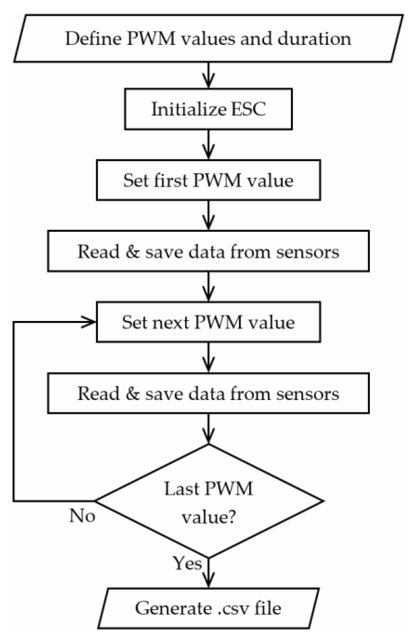
The throttle signal sent to the ESC drive was a standard 50 Hz PWM signal with “ON” time ranging from 1000 to 2000 μs (dependent on the ESC). It is possible to send individual PWM signals (manual mode) or send varying signals defined in the RCbenchmark software measurement script (automated mode). Since the goal was to automate and unify measurements, an available script was modified to take four measurements for each PWM value within one measurement cycle. The script is changing the PWM signal from minimal to a maximal value and vice versa in discrete steps, twice. Every PWM signal is held constant for 10 s after which the PWM “ON” time increases or decreases by 100 μs depending on the step of the measurement cycle. The flowchart of the setup script is shown in Figure 5. Upon completion of the measurement cycle, the .csv file is automatically generated in which the rows represent the actual PWM signal sent to ESC and columns represent the measured values (i.e., thrust, current, and others).
3.3. Identification Procedure
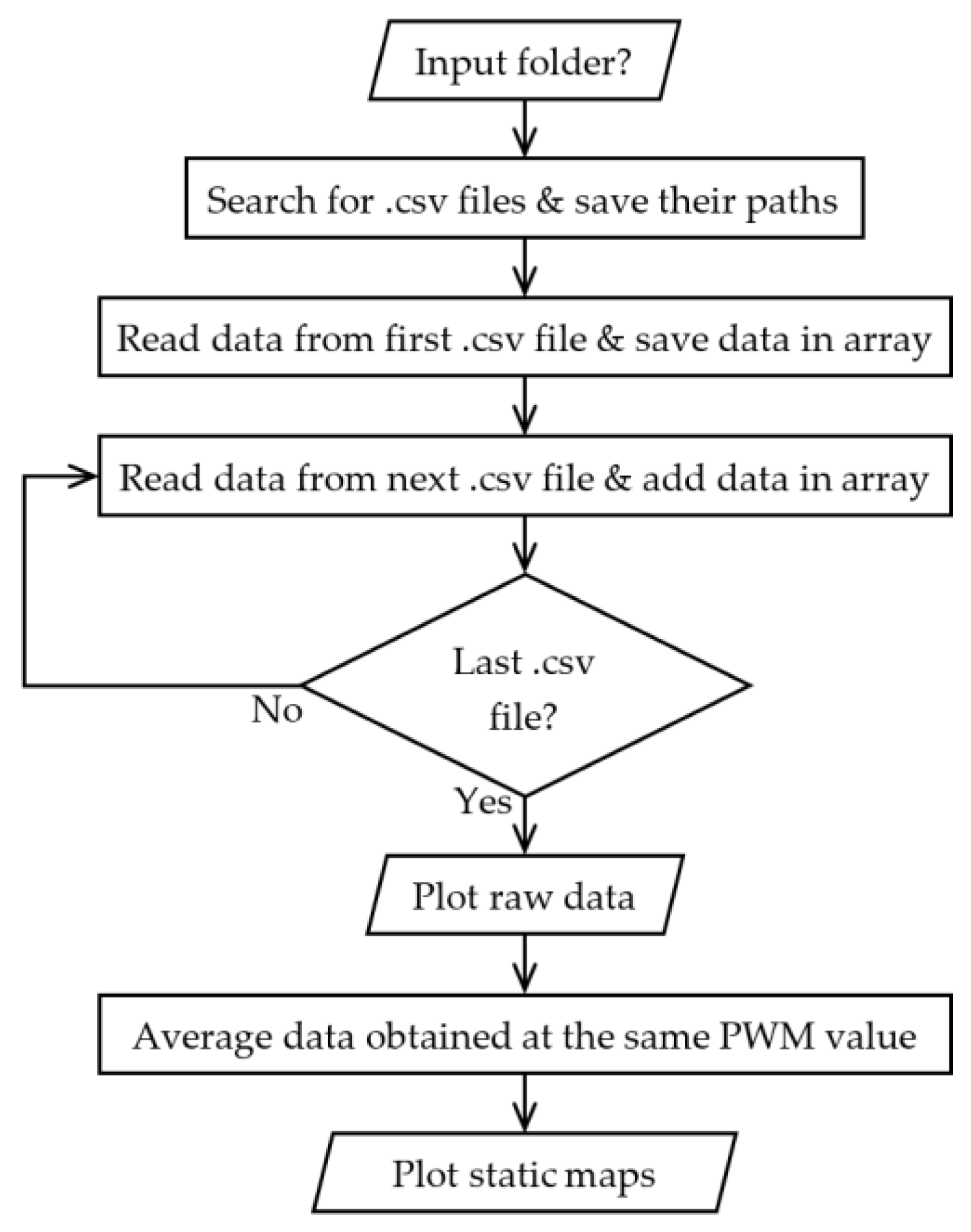
The generated .csv files were loaded, processed, and graphically presented using the MATLAB software package. Regarding a relatively large number of measurements, this process was automated with a customized MATLAB script. The flowchart of the MATLAB script is shown in Figure 6. In the first step, the script finds all .csv files in the defined measurement root folder and in its subfolders. All data from each .csv file is then read and appended into a common data array. Once the array is filled with data from all measurements, raw measurement data are plotted. By averaging measurement data obtained at the same PWM values (and with further data manipulation), output vectors required for EPU static maps were generated and plotted.
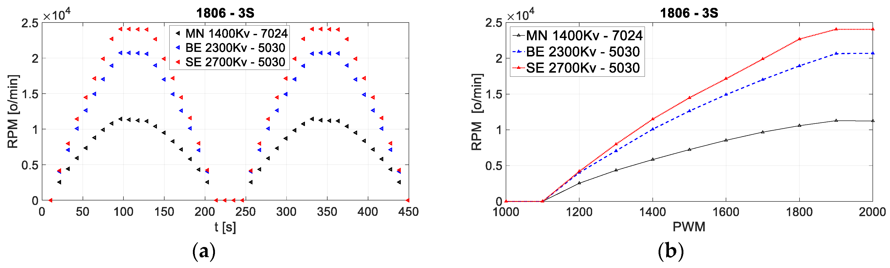
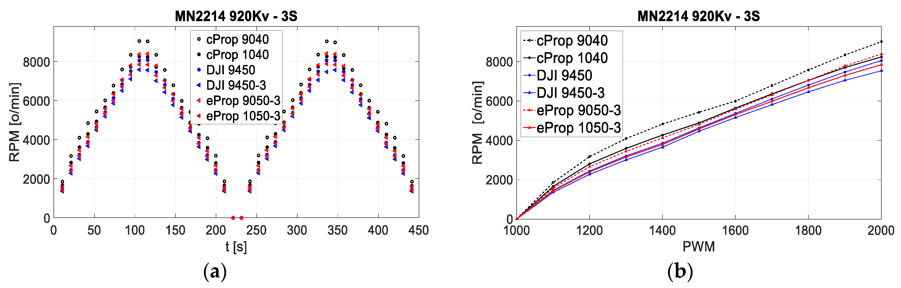
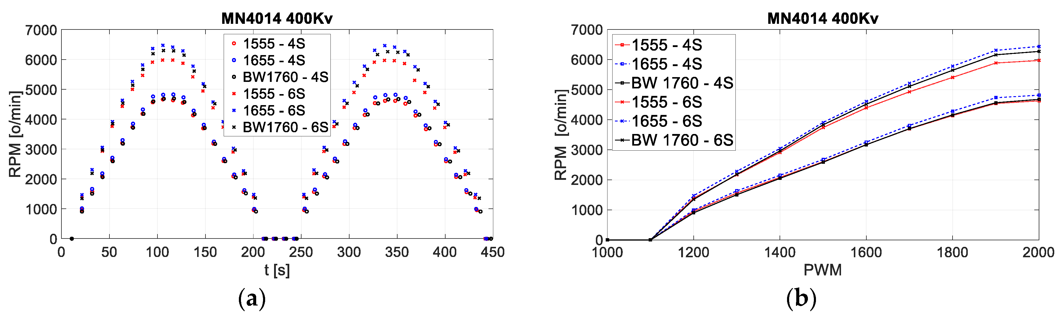
Figure 7, Figure 8 and Figure 9 show the plot of raw data measurement i.e., revolutions per minute (RPM) in relation to measurement time, and a plot of the static maps for the rotor speed measurement in relation to the input PWM signal. The results of other measurements are shown in the next subsection. Three series of measurements were conducted for selected EPU components (as shown in Table 1). The first series represents EPU setup with 1806 motors of different motor constants , the second series represents EPU setup with MN2214 motor and propellers of different geometric characteristics, while the third series represents EPU setup with MN4014 motor and 15″ to 17″ diameter propellers in combination with 4S and 6S LiPo batteries. It can be seen from the figures that lower speeds are expected for motors with lower , and that diverse ESC may differ in the control signal range.
3.4. EPU Static Maps
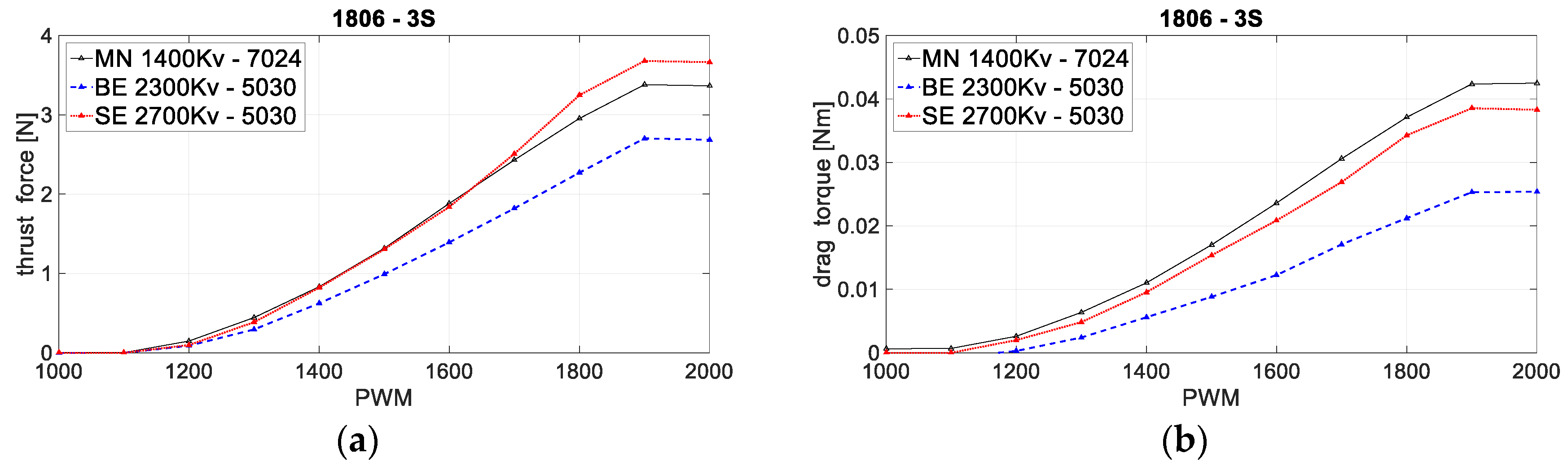
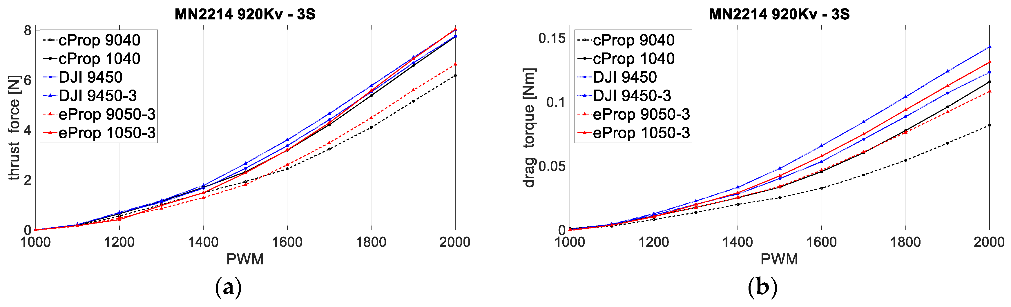
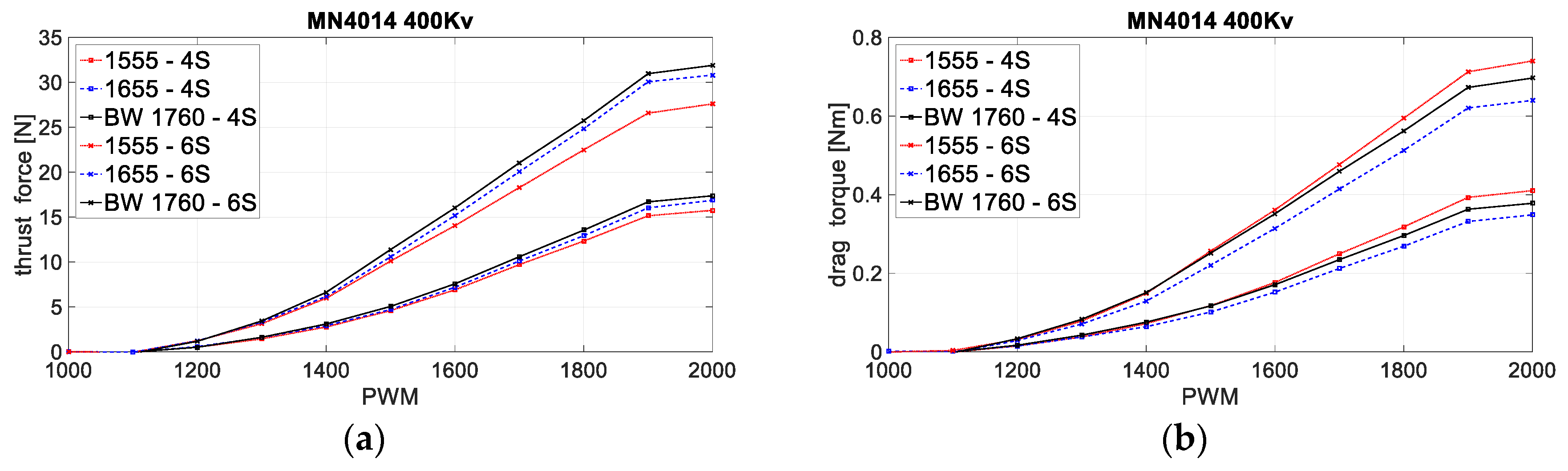
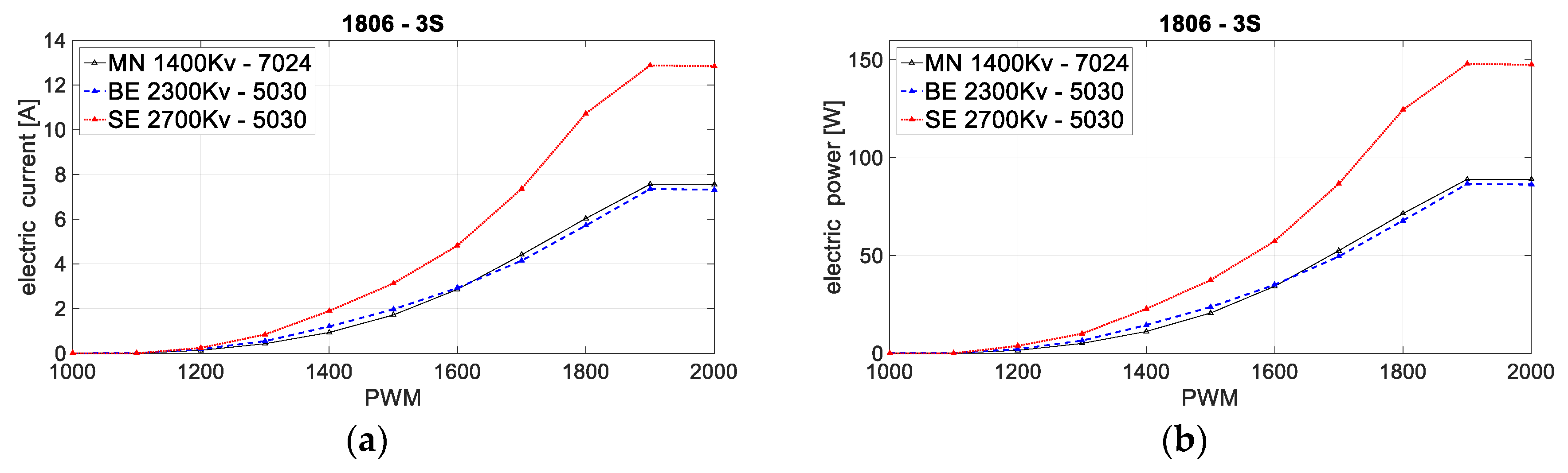
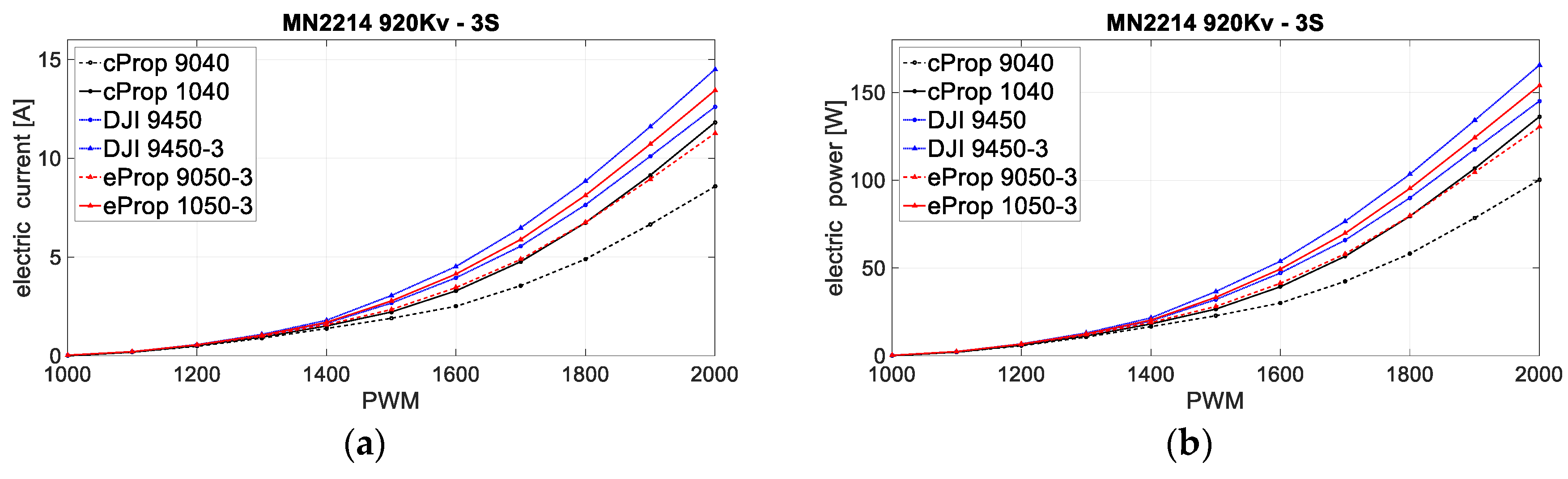
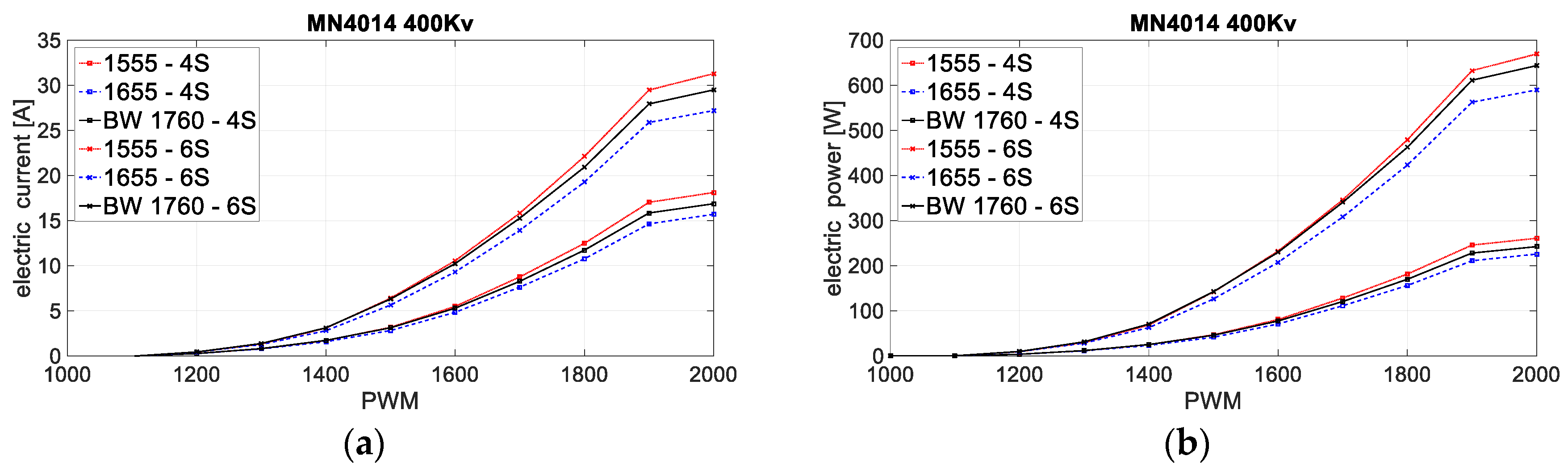
Static maps represent processed data and are the first step in characterization. The identified parameters (contained within arrays) are a function of the control PWM signal. Figure 10, Figure 11 and Figure 12 show static maps of aerodynamic thrust force and drag torque with respect to input PWM signal, while Figure 13, Figure 14 and Figure 15 show static maps of electric current and electric power with respect to input PWM signal, for three series of measurements (three different EPU setups).
For the first setup, 5030 and 7024 propellers were tested, where the first two numbers of the designation define the propeller diameter (5″ and 7″), and the other two numbers the propeller pitch angle (3″ and 2.4″). For the second setup, propellers with 9″ to 10″ diameter and various geometric characteristics were selected and for the third setup, propellers with 15″ to 17″ diameter in combination with 4S and 6S LiPo batteries were selected. Generally, it can be seen that EPU setups with lower , paired with larger propeller diameters, achieve higher aerodynamic forces and torques.
Consequently, as the EPU drag torque increases, the power consumption increases. Electrical consumption is extremely important from the aspect of designing a multirotor UAV with a specific purpose (flight tasks). The first two series of measurements were performed using a 12 V power supply equivalent to a 3S LiPo battery (Figure 13 and Figure 14). The third series (Figure 15) was done with 4S and 6S batteries as a power source. The experimental measurement of electrical quantities was additionally verified using a multifunction logger. Higher power EPUs generally operate at higher voltages.
4. Electric Propulsion System Characterization
The characterization of EPU can be performed in several ways [26,27]. In this research, the characterization was performed based on the obtained three series of static maps. The characterization is necessary for the proper selection of propulsion components, further analysis of the electric propulsion system, and could be a starting point for propulsion system parameters optimization. The characterization procedure can be divided into two parts wherein the first mechanical quantities are considered in the form of aerodynamic forces and moments with respect to the angular velocity of the rotor, and in the second electrical quantities, i.e., electricity consumption.
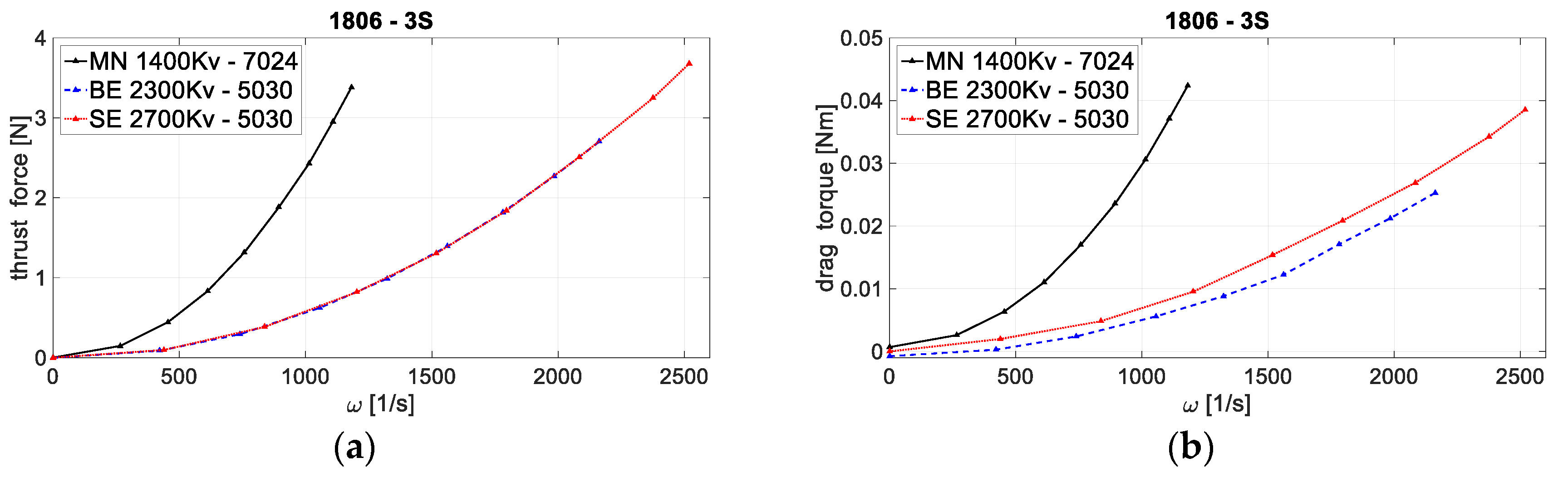
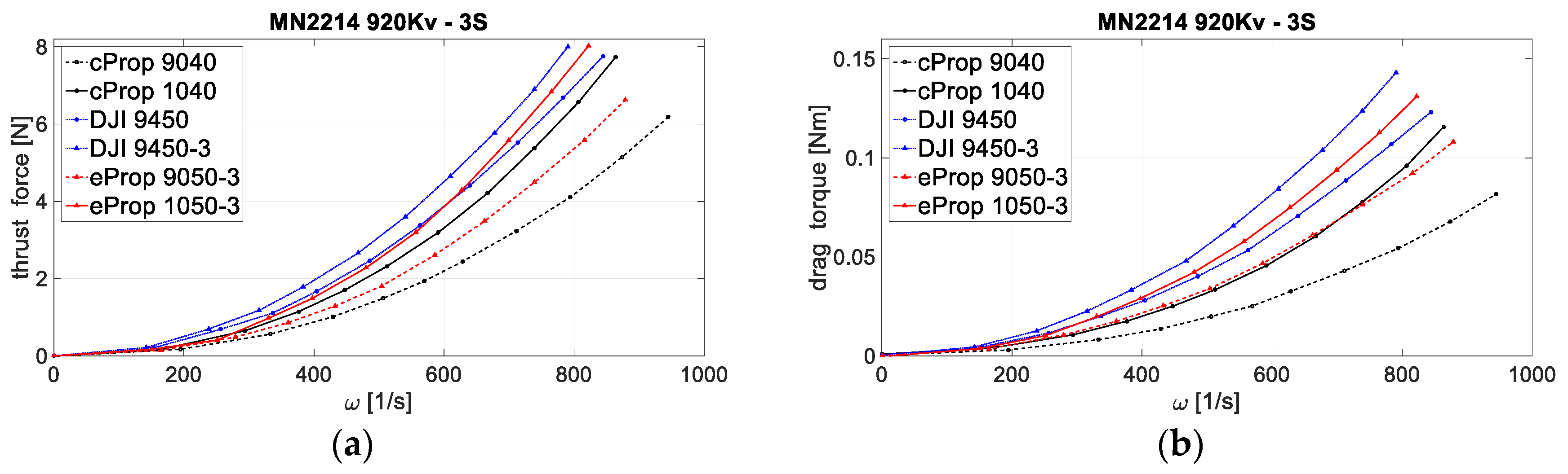
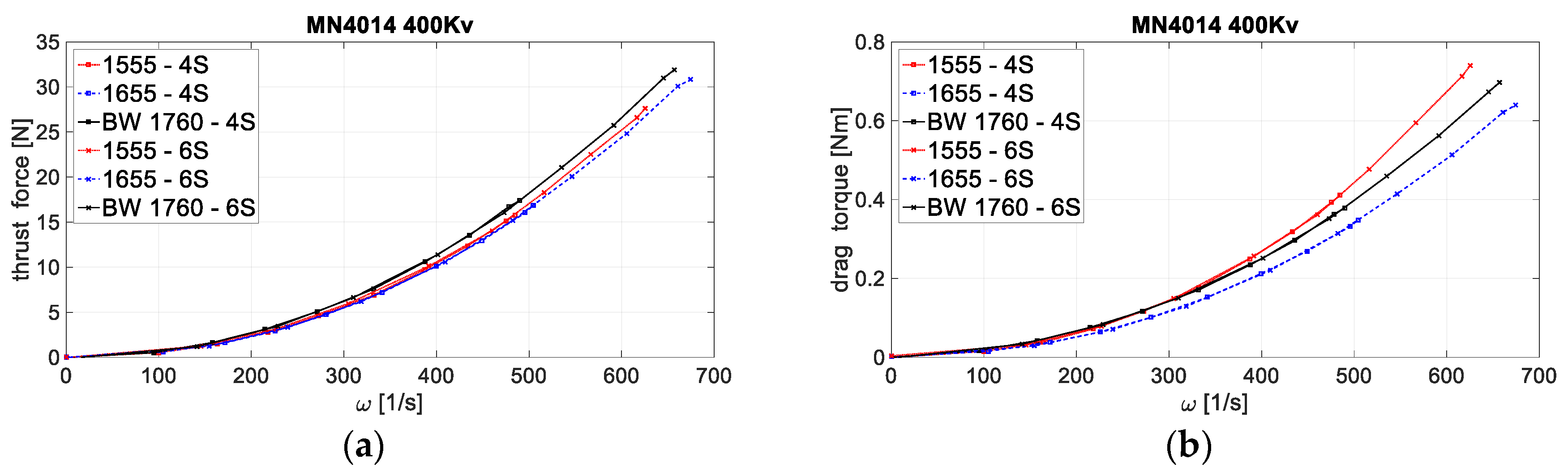
4.1. Aerodynamic Forces and Moments
The aerodynamic forces and moments (thrust force and drag torque), according to Equations (15) and (17), directly depend on the rotor angular velocity. Based on the obtained curves (Figure 16, Figure 17 and Figure 18), it was possible to estimate the factors of aerodynamic forces in the EPU working area for the purposes of conducting computer simulations of the multirotor UAV behavior. The factors can be further investigated through the thrust coefficients and motor power coefficients according to Equations (16) and (18). Figure 16, Figure 17 and Figure 18 show thrust forces and drag torques as a function of rotor angular velocity for three series of measurements (setups). It can be seen that the thrust and torque factors of the EPU depend on the geometry of the propeller, mostly the diameter. Motors with a higher and/or batteries with a larger number of cells increase the angular velocities of the rotor, so as expected, higher thrust forces and consequently drag torques are achieved.
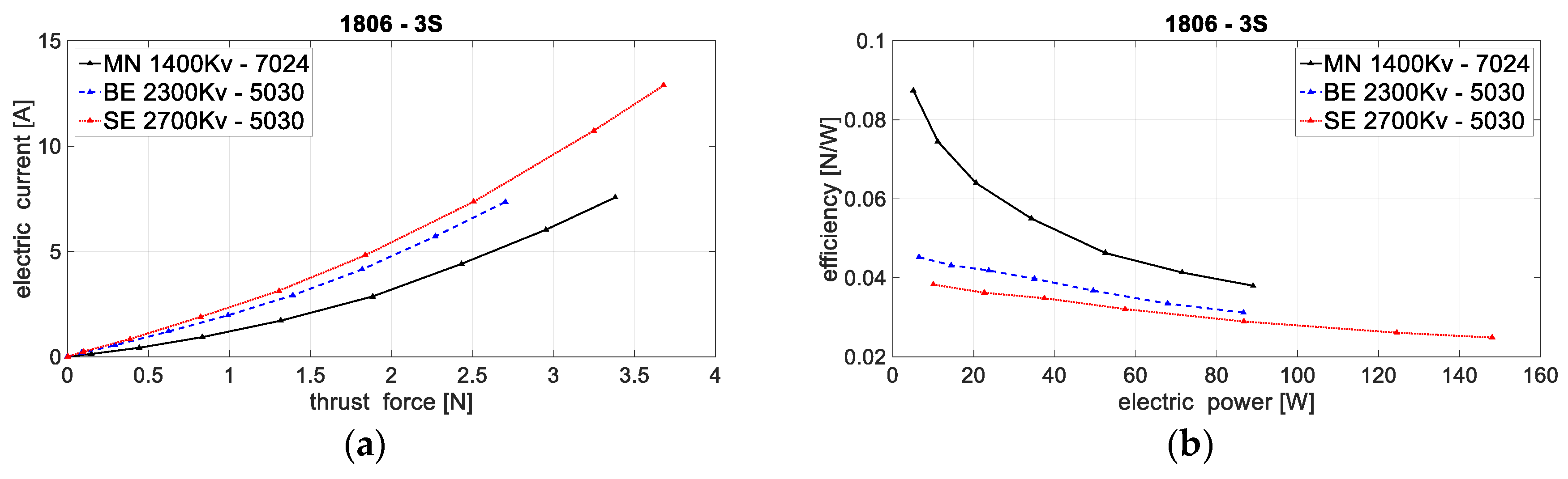
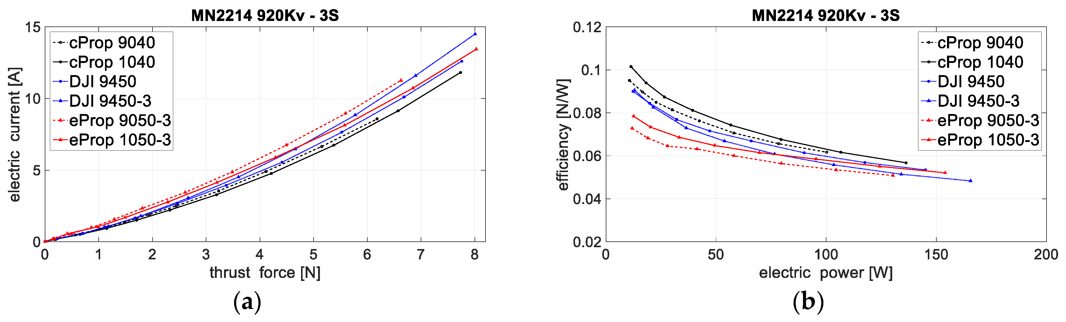
4.2. Energy Consumption and Efficiency
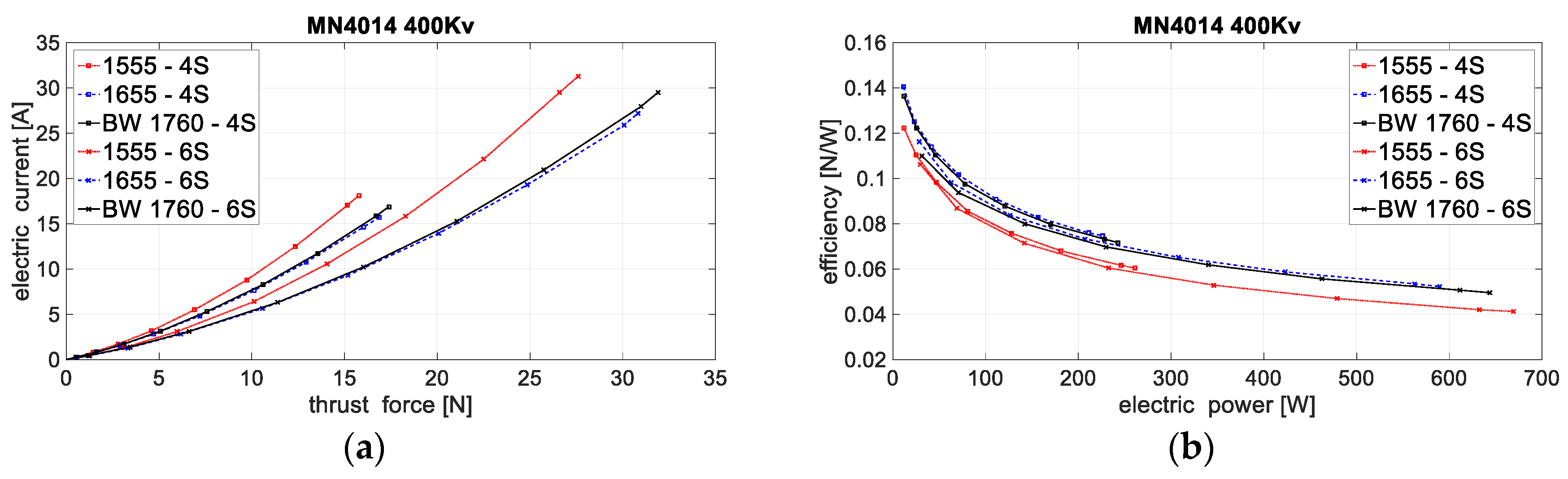
Based on static maps of electrical quantities, the characterization of EPUs in the form of efficiency was performed, since this is a key parameter when designing the system. For the purpose of estimating the flight time, it is necessary to show the electric current depending on the required thrust force for the selected EPUs. Therefore, the overall efficiency of the EPU was represented by the ratio of thrust and electric power and is shown as a function of electric power (energy consumption). Figure 19, Figure 20 and Figure 21 show the electric current depending on the required thrust force and overall efficiency of the EPU for three series of measurements (setups). Based on the obtained curves, the components of the propulsion and energy system can be selected for further analysis.
4.3. Electric Propulsion System Comparison
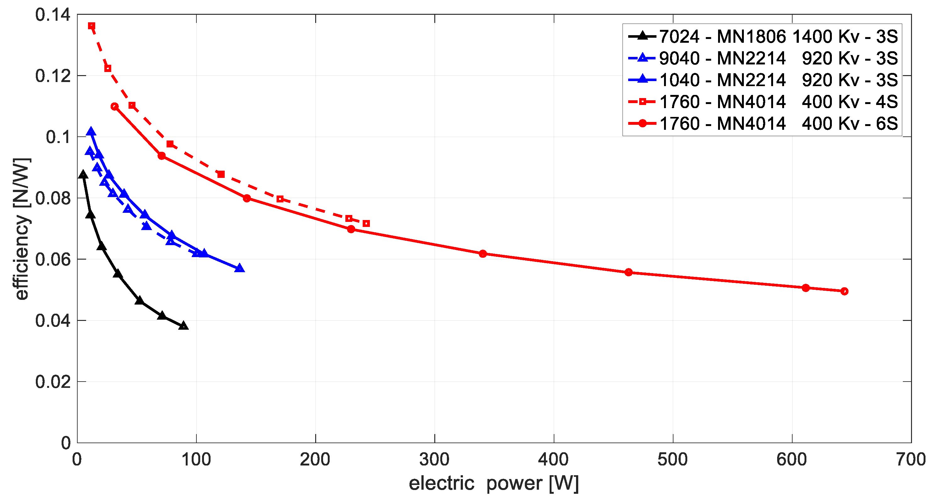
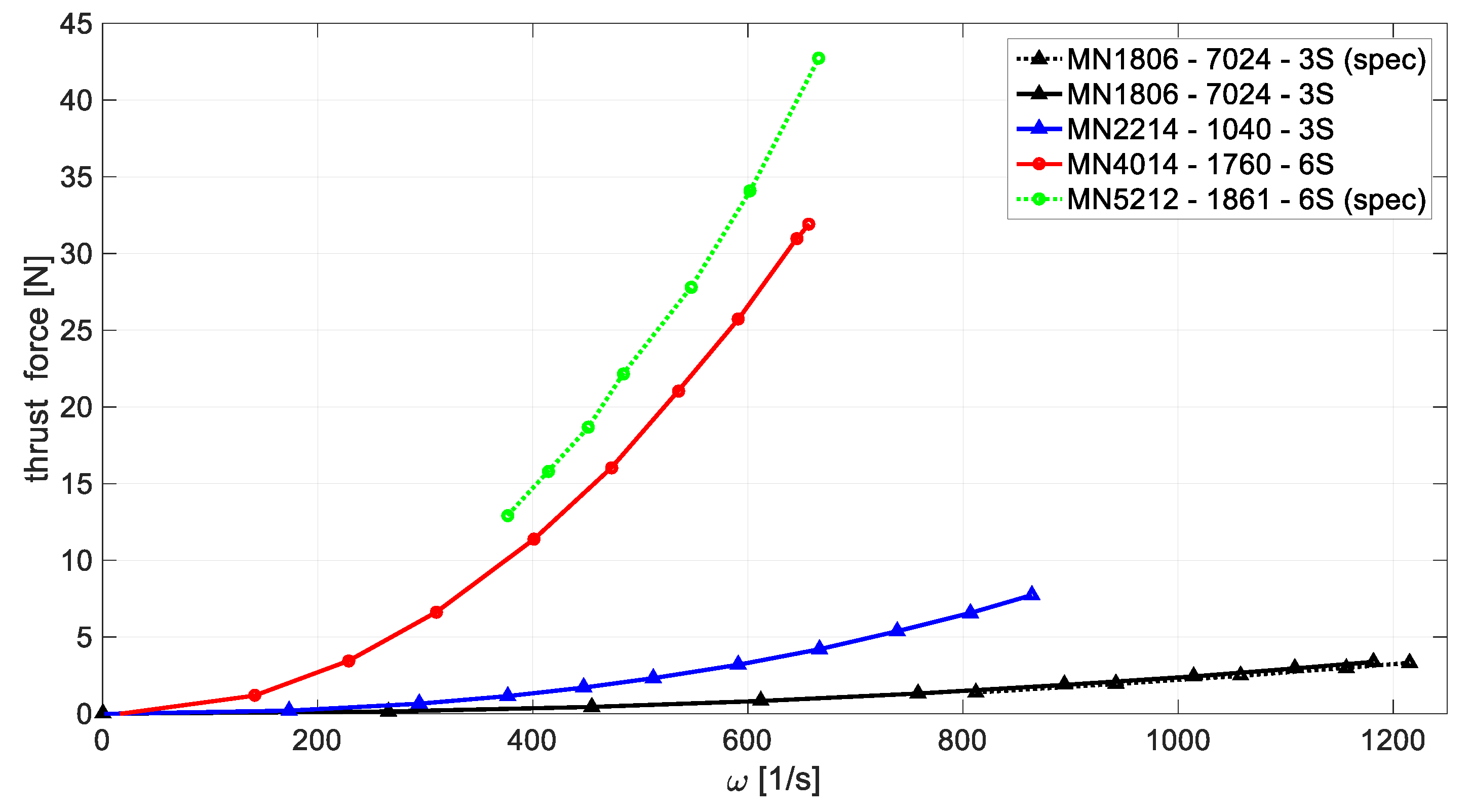
By comparing the EPUs selected on the basis of efficiency for individual EPU setups, it is possible to select the electric propulsion system parameters for a specific aircraft purpose. Figure 22 shows the overall efficiency of the selected EPU where it can be seen that the higher power EPUs have a higher degree of overall efficiency. Figure 23 shows the thrust force with respect to the rotor angular velocity for the selected EPU setups based on experimental measurements and specifications from the EPU manufacturer.
Very important information is the total time that the aircraft can be in the air, which depends on the mission itself, i.e., on the required flight performance and the cargo that the aircraft carries. Based on the characteristic of EPUs, an estimate of the flight time was performed for selected series of multirotor configurations defined by the parameters of the propulsion and energy system. In particular, the basic case of stationary flight for conventional configurations was considered. The drop in battery voltage and the power consumption by the control system (also the equipment system) are ignored. The estimated flight time is defined by the following expression
where is the battery capacity in mAh, and is the electric current at the required thrust force determined according to the characteristics. The required thrust force to achieve a stationary flight depends on the overall multirotor mass. To that end, Table 2 shows the parameters for three different EPU setups with appropriate power source, considered for quadrotor, hexarotor, and octorotor configuration of multirotor UAV. Based on typical values of aircraft () and payload () mass for each configuration, stationary flight time was estimated. An increase in the number of rotors increases available payload mass, but at a cost of higher battery capacity requirement, without a significant increase in flight time.
5. Conclusions
In this paper, a method for characterizing the propulsion system of a multirotor UAV was proposed with the aim of component comparison. The procedure for parameter identification and characterization was presented through the process of experimental identification which includes experimental measurements and signal processing.
Experimental measurements were performed utilizing several types of propellers with different diameters and several medium-sized BLDC motors. Raw measurements were used to generate static maps for the EPU. With static maps of the individual EPU, characterization of the whole electric propulsion system can be performed. The proposed method thus allows a comparison of the various electric propulsion components and their individual impact on the aircraft system. Additionally, a characterized propulsion system can serve as a basis for further aircraft parameters optimization. From the presented results, it can be concluded that higher power EPUs are more efficient and thus results in greater flight autonomy while a greater number of EPUs (more than quadrotor configuration) yields more payload capacity and also more flight autonomy but are negatively affected by higher mass from the EPUs.
The proposed method was also validated by comparison with commercially available data for some of the motors for which manufacturer specifications were available. With a reliable estimate of the EPU parameters, an estimate of the overall performance of the aircraft can be made. As an example, hover time was estimated. The methodological approach to the design of multirotor aircraft is the subject of future research.
Author Contributions
Conceptualization, P.P. and D.K.; methodology, P.P. and D.K.; software, P.P. and M.K.; validation, P.P., D.K., and M.K.; investigation, P.P. and D.K.; data curation, P.P.; writing—original draft, D.K.; writing—review and editing, P.P. and M.K. All authors have read and agreed to the published version of the manuscript.
Funding
This research was funded by European Regional Development Fund, Operational programme competitiveness and cohesion 2014–2020, grant number KK.01.1.1.04.0092 and the APC was funded by KK.01.1.1.04.0092.
Conflicts of Interest
The authors declare no conflict of interest.
References
- Kumar, V.; Michael, N. Opportunities and challenges with autonomous micro aerial vehicles. Int. J. Rob. Res. 2012, 31, 1279–1291. [Google Scholar] [CrossRef]
- Yeom, S.; Cho, I.J. Detection and tracking of moving pedestrians with a small unmanned aerial vehicle. Appl. Sci. 2019, 9, 3359. [Google Scholar] [CrossRef] [Green Version]
- Menéndez, O.; Pérez, M.; Auat Cheein, F. Visual-based positioning of aerial maintenance platforms on overhead transmission lines. Appl. Sci. 2019, 9, 165. [Google Scholar] [CrossRef] [Green Version]
- Li, Y.; Liu, C. Applications of multirotor drone technologies in construction management. Int. J. Constr. Manag. 2018, 19, 401–412. [Google Scholar] [CrossRef]
- Jannoura, R.; Brinkmann, K.; Uteau, D.; Bruns, C.; Joergensen, R.G. Monitoring of crop biomass using true colour aerial photographs taken from a remote controlled hexacopter. Biosyst. Eng. 2015, 129, 341–351. [Google Scholar] [CrossRef]
- Briod, A.; Kornatowski, P.; Zufferey, J.C.; Floreano, D.A. Collision-resilient flying robot. J. Field Robot. 2014, 31, 496–509. [Google Scholar] [CrossRef] [Green Version]
- Yang, B.; He, Y.; Han, J.; Liu, G. Rotor-flying manipulator: Modeling, analysis, and control. Math. Probl. Eng. 2014, 2014, 1–13. [Google Scholar] [CrossRef]
- Nguyen, A.T.; Xuan-Mung, N.; Hong, S.K. Quadcopter adaptive trajectory tracking control: A new approach via backstepping technique. Appl. Sci. 2019, 9, 3873. [Google Scholar] [CrossRef] [Green Version]
- Park, J.; Cho, N. Collision avoidance of hexacopter UAV based on LiDAR data in dynamic environment. Remote Sens. 2020, 12, 975. [Google Scholar] [CrossRef] [Green Version]
- Ikeda, T.; Yasui, S.; Fujihara, M.; Ohara, K.; Ashizawa, S.; Ichikawa, A.; Okino, A.; Oomichi, T.; Fukuda, T. Wall contact by octo-rotor UAV with one DoF manipulator for bridge inspection. In Proceedings of the 2017 IEEE/RSJ International Conference on Intelligent Robots and Systems (IROS), Vancouver, BC, Canada, 24–28 September 2017; pp. 5122–5127. [Google Scholar] [CrossRef]
- Kotarski, D.; Kasać, J. Generalized control allocation scheme for multirotor type of UAVs. In Drones-Applications; Dekoulis, G., Ed.; IntechOpen: London, UK, 2018; pp. 43–58. [Google Scholar] [CrossRef] [Green Version]
- Prior, S.D.; Bell, J.C. Empirical measurements of small unmanned aerial vehicle co-axial rotor systems. J. Sci. Innov. 2011, 1, 1–18. [Google Scholar]
- Haus, T.; Car, M.; Orsag, M.; Bogdan, S. Identification results of an internal combustion engine as a quadrotor propulsion system. In Proceedings of the 2017 25th Mediterranean Conference on Control and Automation (MED), Valletta, Malta, 3–6 July 2017; pp. 713–718. [Google Scholar] [CrossRef]
- Chéron, C.; Dennis, A.; Semerjyan, V.; Chen, Y. A multifunctional HIL testbed for multirotor VTOL UAV actuator. In Proceedings of the 2010 IEEE/ASME International Conference on Mechatronic and Embedded Systems and Applications, Qingdao, China, 15–17 July 2010; pp. 44–88. [Google Scholar] [CrossRef]
- Chovancová, A.; Fico, T.; Chovanec, Ľ.; Hubinsk, P. Mathematical modelling and parameter identification of quadrotor (a survey). Procedia Eng. 2014, 96, 172–181. [Google Scholar] [CrossRef] [Green Version]
- Series 1580 Dynamometer Datasheet. Available online: https://cdn-docs.rcbenchmark.com/wp-content/uploads/2016/01/2016-02-04-RCbenchmark-1580-datasheet.pdf (accessed on 14 October 2019).
- Khan, W.; Nahon, M. Toward an accurate physics-based UAV thruster model. IEEE ASME Trans. Mechatron. 2013, 18, 1269–1279. [Google Scholar] [CrossRef]
- Brazinskas, M.; Prior, S.D.; Scanlan, J.P. An empirical study of overlapping rotor interference for a small unmanned aircraft propulsion system. Aerospace 2016, 3, 32. [Google Scholar] [CrossRef]
- Wang, B.; Hou, Z.; Liu, Z.; Chen, Q.; Zhu, X. Preliminary design of a small unmanned battery powered tailsitter. Int. J. Aerosp. Eng. 2016, 2016, 1–11. [Google Scholar] [CrossRef] [Green Version]
- Gatti, M.; Giulietti, F.; Turci, M. Maximum endurance for battery-powered rotary-wing aircraft. Aerosp. Sci. Technol. 2015, 45, 174–179. [Google Scholar] [CrossRef]
- Kotarski, D.; Piljek, P.; Brezak, H.; Kasać, J. Chattering free tracking control of a fully actuated multirotor with passively tilted rotors. Trans. Famena 2018, 42, 1–14. [Google Scholar] [CrossRef] [Green Version]
- Lee, B.S.; Tullu, A.; Hwang, H.Y. Optimal design and design parameter sensitivity analyses of an eVTOL PAV in the conceptual design phase. Appl. Sci. 2020, 10, 5112. [Google Scholar] [CrossRef]
- Gamazo-Real, J.C.; Vazquez-Sanchez, E.; Gomez-Gil, J. Position and speed control of brushless DC motors using sensorless techniques and application trends. Sensors 2010, 10, 6901–6947. [Google Scholar] [CrossRef] [PubMed] [Green Version]
- Kotarski, D.; Krznar, M.; Piljek, P.; Šimunić, N. Experimental identification and characterization of multirotor UAV propulsion. J. Phys. Conf. Ser. 2017, 870, 1–9. [Google Scholar] [CrossRef] [Green Version]
- PowerLog 6S Manual. Available online: https://www.progressiverc.com/media/PowerLog%206S%20Manual.pdf (accessed on 10 October 2019).
- Szafranski, G.; Czyba, R.; Błachuta, M. Modeling and identification of electric propulsion system for multirotor unmanned aerial vehicle design. In Proceedings of the 2014 International Conference on Unmanned Aircraft Systems (ICUAS), Orlando, FL, USA, 27–30 May 2014; pp. 470–476. [Google Scholar] [CrossRef]
- Sartori, D.; Yu, W. Experimental Characterization of a Propulsion System for Multi-rotor UAVs. J. Intell. Robot. Syst. 2019, 96, 529–540. [Google Scholar] [CrossRef]
Figure 1.
Multirotor unmanned aerial vehicle (UAV) reference coordinate systems.

Figure 2.
Reference coordinate system of the propulsion system i-th rotor.

Figure 3.
Electric propulsion unit (EPU) schematic.

Figure 4.
RCbenchmark measurement system: (a) hardware; (b) wired measurement setup.

Figure 5.
Setup script flowchart.

Figure 6.
MATLAB script flowchart.

Figure 7.
Rotor RPM for setup with 1806 series of BLDC motor: (a) raw measurement; (b) RPM static maps.
Figure 7.
Rotor RPM for setup with 1806 series of BLDC motor: (a) raw measurement; (b) RPM static maps.

Figure 8.
Rotor RPM for setup with MN 2214 BLDC motor: (a) raw measurement; (b) RPM static maps.

Figure 9.
Rotor RPM for setup with MN 4014 BLDC motor: (a) raw measurement; (b) RPM static maps.

Figure 10.
Static maps—1806 BLDC series: (a) thrust force; (b) drag torque.

Figure 11.
Static maps—MN 2214 BLDC motor: (a) thrust force; (b) drag torque.

Figure 12.
Static maps—MN 4014 BLDC motor: (a) thrust force; (b) drag torque.

Figure 13.
Static maps—1806 BLDC series: (a) electric current; (b) electric power.

Figure 14.
Static maps—MN 2214 BLDC motor: (a) electric current; (b) electric power.

Figure 15.
Static maps—MN 4014 BLDC motor: (a) electric current; (b) electric power.

Figure 16.
Aerodynamic effects with respect to rotor angular velocity, 1806 BLDC series: (a) thrust force; (b) drag torque.
Figure 16.
Aerodynamic effects with respect to rotor angular velocity, 1806 BLDC series: (a) thrust force; (b) drag torque.

Figure 17.
Aerodynamic effects with respect to rotor angular velocity, MN 2214 BLDC motor: (a) thrust force; (b) drag torque.
Figure 17.
Aerodynamic effects with respect to rotor angular velocity, MN 2214 BLDC motor: (a) thrust force; (b) drag torque.

Figure 18.
Aerodynamic effects with respect to rotor angular velocity, MN 4014 BLDC motor: (a) thrust force; (b) drag torque.
Figure 18.
Aerodynamic effects with respect to rotor angular velocity, MN 4014 BLDC motor: (a) thrust force; (b) drag torque.

Figure 19.
Energy consumption of 1806 BLDC series: (a) electric current with respect to thrust force; (b) overall efficiency.
Figure 19.
Energy consumption of 1806 BLDC series: (a) electric current with respect to thrust force; (b) overall efficiency.

Figure 20.
Energy consumption of MN 2214 BLDC motor: (a) electric current with respect to thrust force; (b) overall efficiency.
Figure 20.
Energy consumption of MN 2214 BLDC motor: (a) electric current with respect to thrust force; (b) overall efficiency.

Figure 21.
Energy consumption of MN 4014 BLDC motor: (a) electric current with respect to thrust force; (b) overall efficiency.
Figure 21.
Energy consumption of MN 4014 BLDC motor: (a) electric current with respect to thrust force; (b) overall efficiency.

Figure 22.
The overall efficiency of selected EPUs.

Figure 23.
Thrust force with respect to the rotor angular velocity of selected EPU setups.


Table 1.
Considered EPU setups for selected brushless DC (BLDC) motors.
| BLDC Motor Designation | ||||
|---|---|---|---|---|
| SE1806 | 2700 | 5″ | 3S | 20 A |
| BE1806 | 2300 | 5″ | 3S | 15 A |
| MN1806 | 1400 | 7″ | 3S | 15 A |
| MN2214 | 920 | 9–10″ | 3S | 20 A |
| MN4014 | 400 | 15–17″ | 4–6S | 40 A |
Table 2.
Multirotor UAV parameters and estimated flight time.
| EPU Setup | MN 1806–7024–3S | MN 2214–1040–3S | MN 4014–1760–6S | ||||||
|---|---|---|---|---|---|---|---|---|---|
| 4 | 6 | 8 | 4 | 6 | 8 | 4 | 6 | 8 | |
| (g) | 850 | 1050 | 1250 | 1150 | 1800 | 2400 | 3000 | 4700 | 6400 |
| (g) | 100 | 200 | 300 | 500 | 750 | 1000 | 2000 | 4000 | 6000 |
| (mAh) | 4000 | 5000 | 6000 | 5000 | 10,000 | 15,000 | 10,000 | 20,000 | 30,000 |
| (min) | 14.8 | 15.2 | 15.4 | 16.6 | 21.2 | 23.8 | 21.2 | 23 | 23.6 |
Publisher’s Note: MDPI stays neutral with regard to jurisdictional claims in published maps and institutional affiliations. |
© 2020 by the authors. Licensee MDPI, Basel, Switzerland. This article is an open access article distributed under the terms and conditions of the Creative Commons Attribution (CC BY) license (http://creativecommons.org/licenses/by/4.0/).
Share and Cite
MDPI and ACS Style
Piljek, P.; Kotarski, D.; Krznar, M. Method for Characterization of a Multirotor UAV Electric Propulsion System. Appl. Sci. 2020, 10, 8229. https://0-doi-org.brum.beds.ac.uk/10.3390/app10228229
AMA Style
Piljek P, Kotarski D, Krznar M. Method for Characterization of a Multirotor UAV Electric Propulsion System. Applied Sciences. 2020; 10(22):8229. https://0-doi-org.brum.beds.ac.uk/10.3390/app10228229
Chicago/Turabian StylePiljek, Petar, Denis Kotarski, and Matija Krznar. 2020. "Method for Characterization of a Multirotor UAV Electric Propulsion System" Applied Sciences 10, no. 22: 8229. https://0-doi-org.brum.beds.ac.uk/10.3390/app10228229
Note that from the first issue of 2016, this journal uses article numbers instead of page numbers. See further details here.