Article

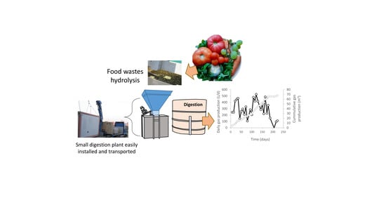
Description of a Decentralized Small Scale Digester for Treating Organic Wastes

by
Rubén González
1,
Daniel Blanco
1,
Judith González-Arias
1,
José García-Cascallana
2 and
Xiomar Gómez
1,*
1
Chemical and Environmental Bioprocess Engineering Group, Natural Resources Institute (IRENA), University of León, 24009 León, Spain
2
School of Industrial Engineering, Computer Science and Aerospace, University of León, Campus Vegazana, 24009 León, Spain
*
Author to whom correspondence should be addressed.
Submission received: 11 September 2020 / Revised: 25 September 2020 / Accepted: 26 September 2020 / Published: 29 September 2020
(This article belongs to the Special Issue Small-Scale Anaerobic Digestion for Biogas Production)

Abstract

:
This manuscript deals with the detailed design of a small digestion prototype intended as a commercial unit fully operational to cover the demand for decentralized treatment of wastes. These plants are highly affected by the complex nature of wastes giving rise to different operating problems that should be considered in detail. This paper describes the design and start-up strategy of a small-scale digestion plant with a volume of 8 m3 designed to operate with a hydrolysis pretreatment unit. The plant was designed to treat fruit and vegetable wastes as substrates derived from a local processing food factory. The performance of the plant during fed-batch operation was reported. The strategy of inoculating the reactor only to a third of its original volume and subsequently increasing the volume of the reactor by using the fed-batch mode was inadequate. The acid pH of the feeding substrate resulted in the application of a low organic loading rate with a volumetric variation of just 19.7 L/d. The performance of the plant was evaluated at non-steady state conditions and resulted in excessive destruction of volatile solids due to the low nitrogen content of the feeding substrate. The prototype reported a specific methane production of 232 L/kg volatile solids despite the low feeding rate supplemented.

Graphical Abstract

1. Introduction

Anaerobic digestion has been demonstrated to be a suitable technology for the treatment of organic wastes. Several other technologies are available for transforming organic materials; however, the degradation process of biodegradable compounds using anaerobic digestion results in biogas which can be further valorized for producing energy. This process translates into significant advantages over other management strategies, such as landfilling and waste-to-energy incineration [1]. The process involves degradation under anaerobic conditions of the complex material to produce soluble compounds that can be easily assimilated by fermentative bacteria and methanogens.
Animal manures and food wastes are ideal substrates for anaerobic digestion due to their high humidity content and high degradation potential. There are several limitations to this process usually associated with the slow rate of hydrolysis when dealing with particulate material. However, some pretreatments have been proposed as suitable technologies for enhancing degradation. Some of these pretreatment options have been extensively studied, including sound cavitation [2], high-pressure homogenization [3], thermal hydrolysis [4,5], chemical pretreatment/post-treatment [6,7,8], along with combinations of these different alternatives. Other methods are more recent such as the case of aeration for degrading complex compounds and electrooxidation [9,10,11].
When attempting to increase the efficiency of the digestion process, the energy associated with all operations intended for enhancing biogas yields is significantly relevant and should be considered. Thus, all additional operating units and processes, which in some cases can present high energy demand, may finally fail in attaining any possible benefit associated with higher methane production because of the extra demand of energy required [12].
Other relevant aspects that should be carefully evaluated are the scale of the digestion plant and the transportation distance from the collection point of the organic material to the treatment center. Therefore, economy of scale positively affects the feasibility of the plant. In the case of treating manures, Piñas et al. [13] estimated that, for the Brazilian scenario, the economic viability was attained for plants with electrical power higher than 740 kWe. However, along with scale effect, the availability of an increasing amount of biomass, all year round and in enough quantities to represent a stable supply of raw materials, should also be taken into account. Thus, the location of such plants should be relatively close to the source point of waste generation because an excessive distance negatively affects the overall economy of the process. Rajendran and Murthy [14] estimated that the transportation distance of feedstock must not exceed 20–30 km (two-way) to meet economy sustainability criteria.
The best location sites for co-digestion power plant have been calculated, minimizing transport costs and considering technical, environmental, and social restrictions [15]. On the basis of these aspects, in recent years, the implementation of decentralized units for the treatment of waste is gaining relevance. These small treatment units may find a niche in many developing countries where several regions exist in which no central sewage systems are available, thus, the responsibility of wastewater management falls on individual citizens or businesses through decentralized systems [16].
When dealing with organic wastes, the approach of waste to energy and recycling options can be challenging. The well-known waste hierarchy considers that recycling waste is a preferable alternative to incineration or landfilling (but not to waste prevention). However, beyond a certain threshold, the costs of recycling increase to an unacceptable level and more than offset the marginal benefits of further separation and material recovery [17]. Decentralized units for treating organic wastes and wastewater may become a reasonable choice when population density or economic activity does not ensure a sufficient amount of waste materials to provide enough supply for large centralized systems.
Obtaining energy from decentralised waste treatment units offers the advantage of valorizing local residual biomass, thus optimizing their production and consumption [18]. The composting of organics is an example of a successful implementation of decentralization. Decentralized composting enables local reuse of organic matter and can help to decrease the cost and efforts associated with the transport of wastes, processing, and treatment. [19]. Anaerobic digestion requires higher installation costs than composting [20] and the complexity of implementing this technology is a constraint when considering decentralized digestion units. The description of technology and performance associated with decentralized units intended for the treatment of wastes is of great relevance, given the great need of improving environmental quality in many developing countries.
In the present manuscript, the description of a flexible decentralized treatment unit dedicated to the degradation of fruit and vegetable wastes is performed giving detailed indications of its components and operating conditions with the aim of becoming a guide for implementing small digestion units in developing countries. The manuscript contains a description regarding the start-up of the decentralized plant and its treatment capacity, and thus is in line with the compromise that should be adopted by scientific literature and research to move in a direction to provide sustainable solutions for low-middle income countries and appropriate technologies for boosting the circular economy [21].
The present manuscript contains a description of the plant configuration, treatment capacity, and finally the results obtained from the start-up of the digestion reactor, with the aim of providing details regarding the construction and performance of small-scale digestion systems which can be replicated in different scenarios.

2. Materials and Methods

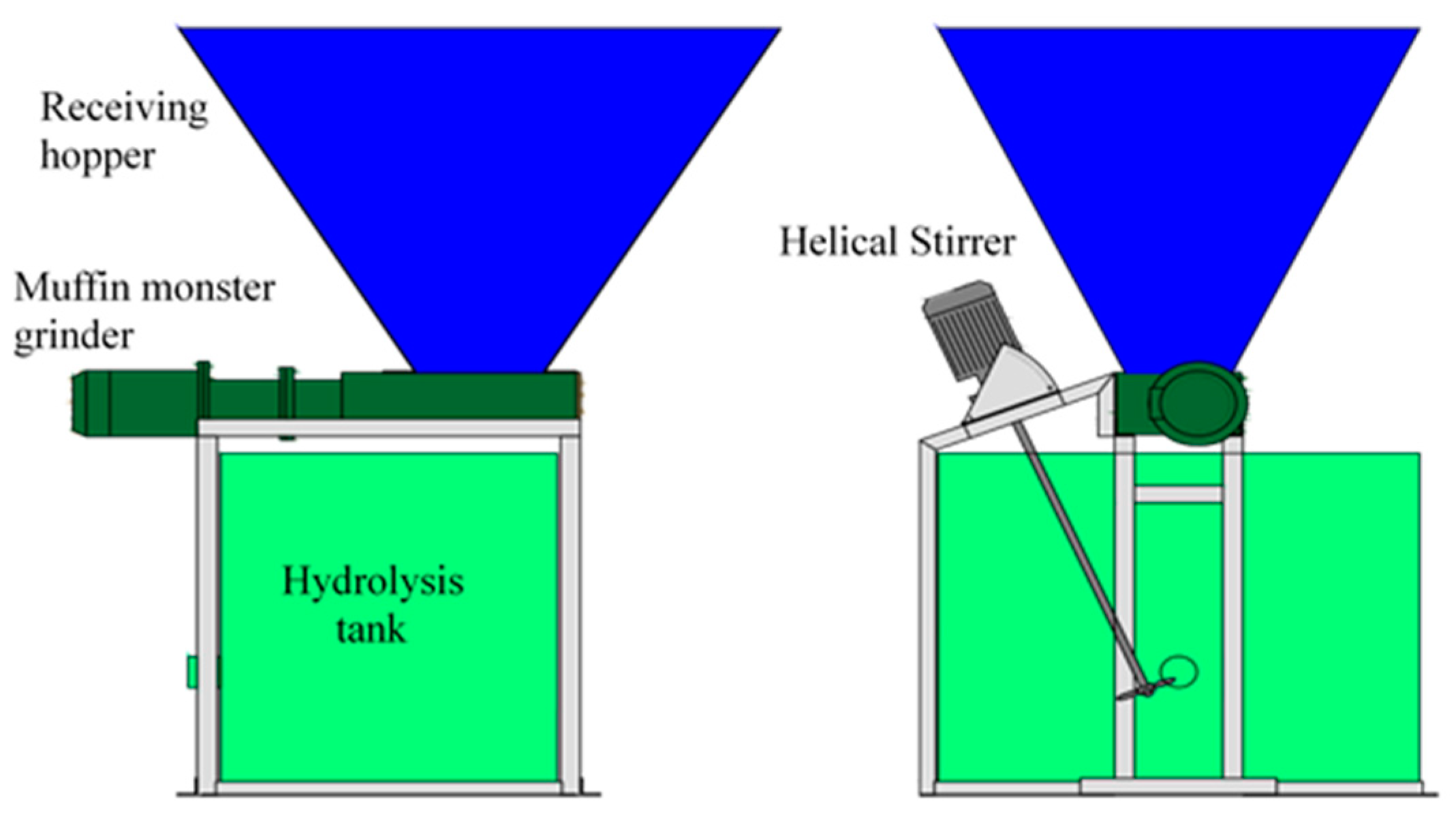
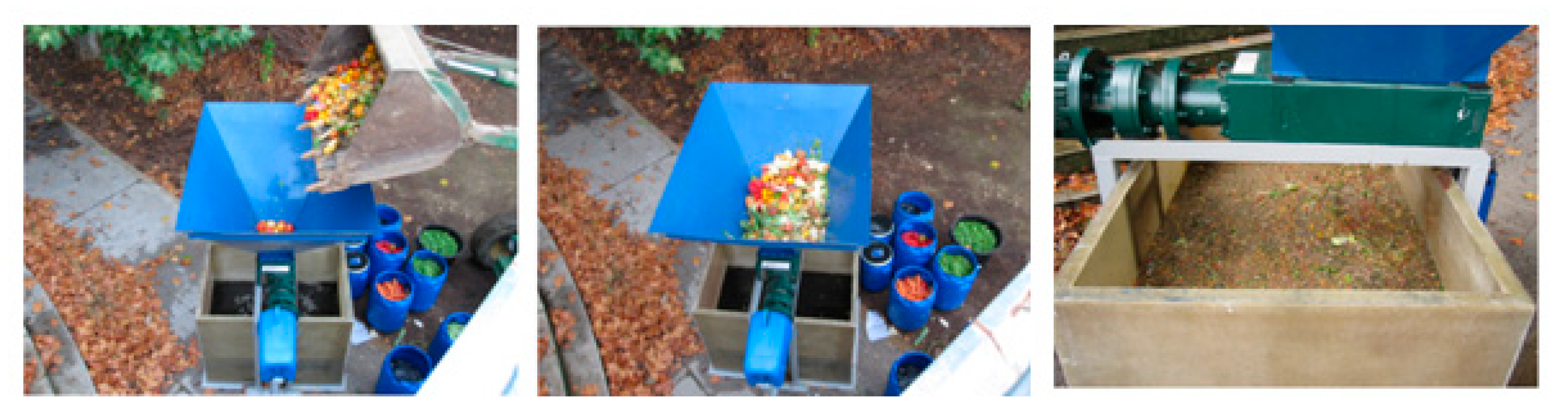
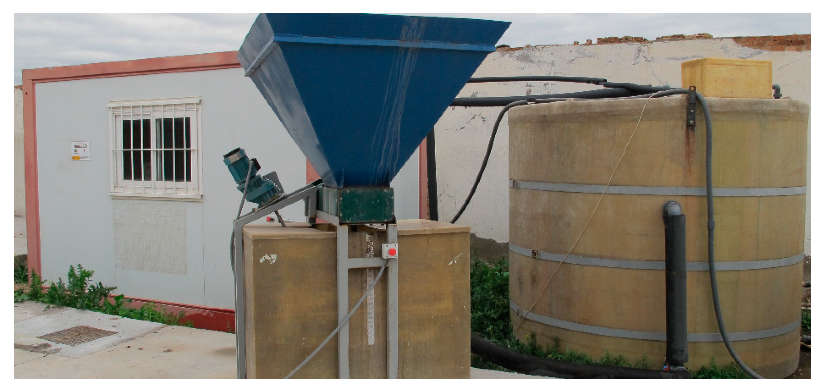
2.1. Pretreatment Unit

The pretreatment unit was designed to receive fruit and vegetable wastes derived from a local company located near Toledo (Spain) which was dedicated to the production of fruit and salads ready to eat. The pretreatment unit consisted of a receiving hopper which was made of a 4 mm thick sheet steel. This unit contained a grinder 2200 W JWCE Muffin Monster Model 30005-0012 for reducing the particle size of the feeding material (see Figure 1). The hydrolysis tank was made of fiberglass and polyester resin and had a capacity of 595 L, which was enough for storing the raw material and carrying out partial hydrolysis prior to submitting the feeding to the digestion reactor. The tank was equipped with a GOLDMASTER Helical Stirrer Model AE-VRR of 650 W. The receiving hopper was installed above the Muffin Monster grinder and this in turn above the top of the hydrolysis tank.

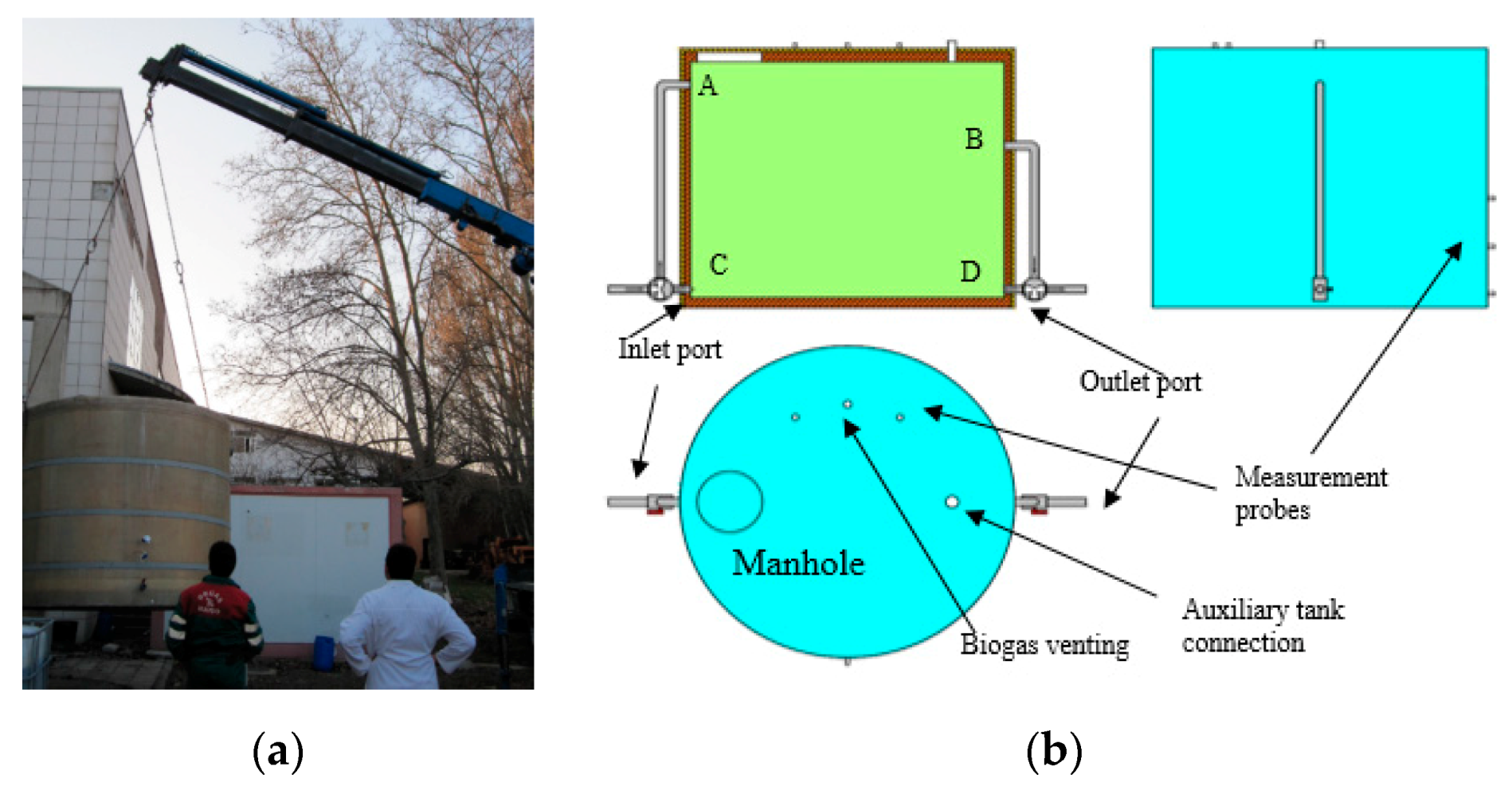
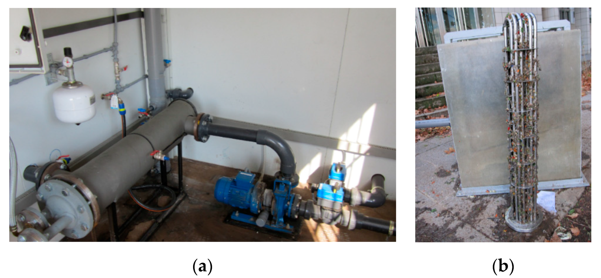
2.2. Anaerobic Reactor

The main digester had a cylindrical shape, was positioned vertically, and was made of fiberglass and vinyl ester resin with dimensions of 2.40 m in diameter and 1.94 m in height, accounting for a total internal volume of 8776 L and a useful volume of 7200 L. This cylinder was covered by the following layers: (1) a 5 cm thick polyurethane foam insulation layer on the ferrule and 8 cm at the base, (2) an intermediate layer of 1 cm thick polyester resin to increase its structural strength, (3) a 3 cm layer of insulation made of rock wool, and (4) an exterior structure of galvanized sheet metal of 1 mm thick to increase resistance to weathering. The digester had external dimensions of 2.60 m in diameter and 2.20 m in height. Figure 2a shows the anaerobic reactor ready for shipment, whereas Figure 2b represents the configuration of the unit and ports positioning. The plant was installed near Toledo at the facility of Comapitol S.L. This company produces organic amendments from source-separated organic materials of high quality. The organics are carefully selected and composted in this facility to produce a mature product with high agronomic characteristics.
The digester had 4 ports, 2.5 inches in diameter, as indicated in Figure 2b by the letters A, B, C and D. The two inlet ports were located diametrically opposite to the two outlet ports, configuring the entry and exit sections of the digester. The two bottom ports (C and D) were located slightly above the inner base of the tank, whilst the other top ports (A and B) were located at different heights. The port denoted as A was placed near the upper base, whereas the second port (B) was placed at a lower position, slightly above the half-height of the tank. This arrangement was selected in order to facilitate the manual operation of piping and valves and in order to configure different flow paths within the digester (up-up, down-down, up-down, and down-up).
The digester also had 3 additional ports, 1 inch in diameter, located in a perpendicular plane to the one formed by the inlets-outlet ports. These ports were located at different heights and were intended for sampling and for sensor housing installation. The top cover of the reactor had a 2 inch port which connected the auxiliary tank with the anaerobic reactor. The top cover also had a 1.25 inch port dedicated to the release of biogas derived from the fermentation process. This port was also located on the top cover along with a manhole to allow access to the interior of the digester for carrying out maintenance tasks whenever necessary.
A temperature probe type Pt100 CORREGE Model D05984 was located in the digester ferrule at a medium height for measuring process temperature. A pressure sensor WIKA Model S11 was located on the top of the reactor for measuring biogas pressure. Another WIKA Model S11 sensor was located at the bottom of the digester ferrule for measuring hydrostatic pressure and indirectly calculated the filling volume of the digester.

2.3. Auxiliary Tank

The auxiliary tank was a cylinder of polyethylene high-density (PE-HD) with a capacity of 220 L, located in a horizontal position. This tank had three ports at the top of its ferrule. The first of these was a 2 inch port for connecting this tank with the top of the anaerobic reactor. The second port was a 2 inch outlet port for connecting the 400 W FOP drain auxiliary submersible pump which was housed inside the tank. The third port was provided with a cable gland for installing the electrical supply line of the drain auxiliary pump. On one of its sides, there was a 2.5 inch port for connecting with the bottom of the anaerobic reactor.

2.4. Digestate Storage Tank

The tank for storing digestate was a standard international bulk container for storing liquids (IBC tank) made of moulded high-density polyethylene with a capacity of 1000 L. On the upper part, the top cover had an intake for receiving digested sludge pumped from the anaerobic reactor by the auxiliary pump. The bottom section of the storage tank had another port for liquid withdrawal.

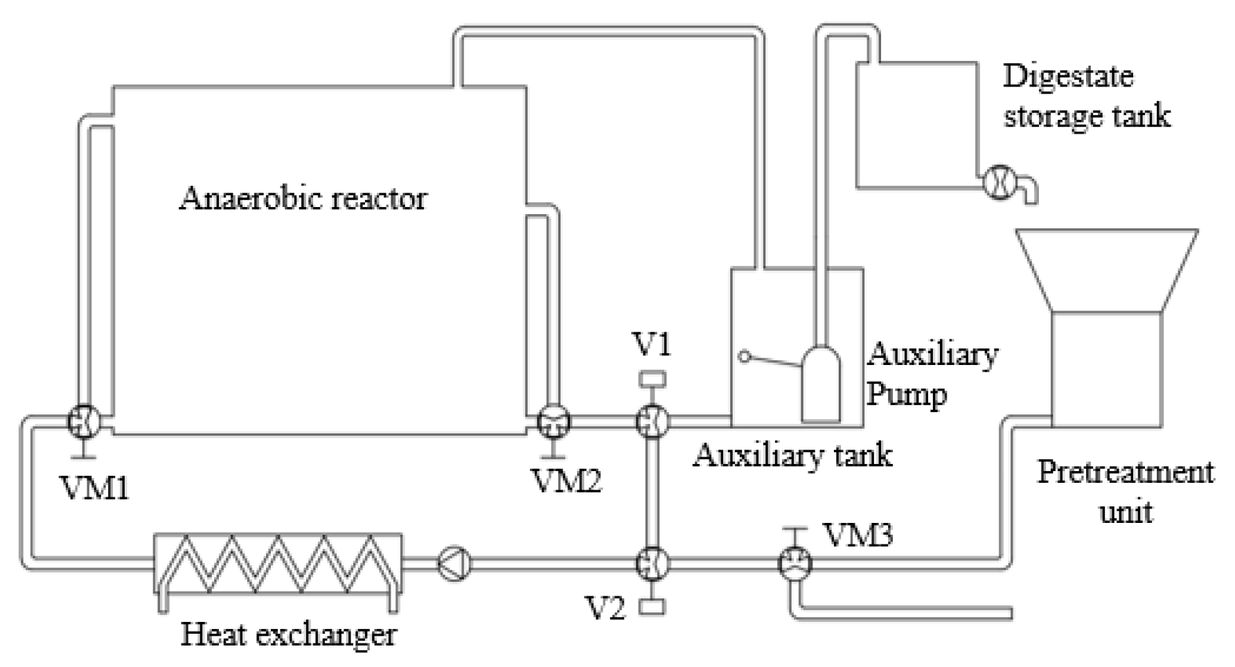
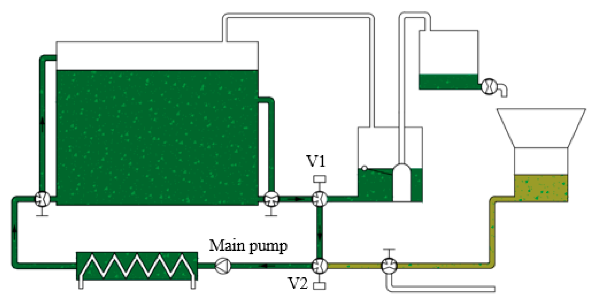
2.5. Auxiliary Equipment, Piping, and Valves
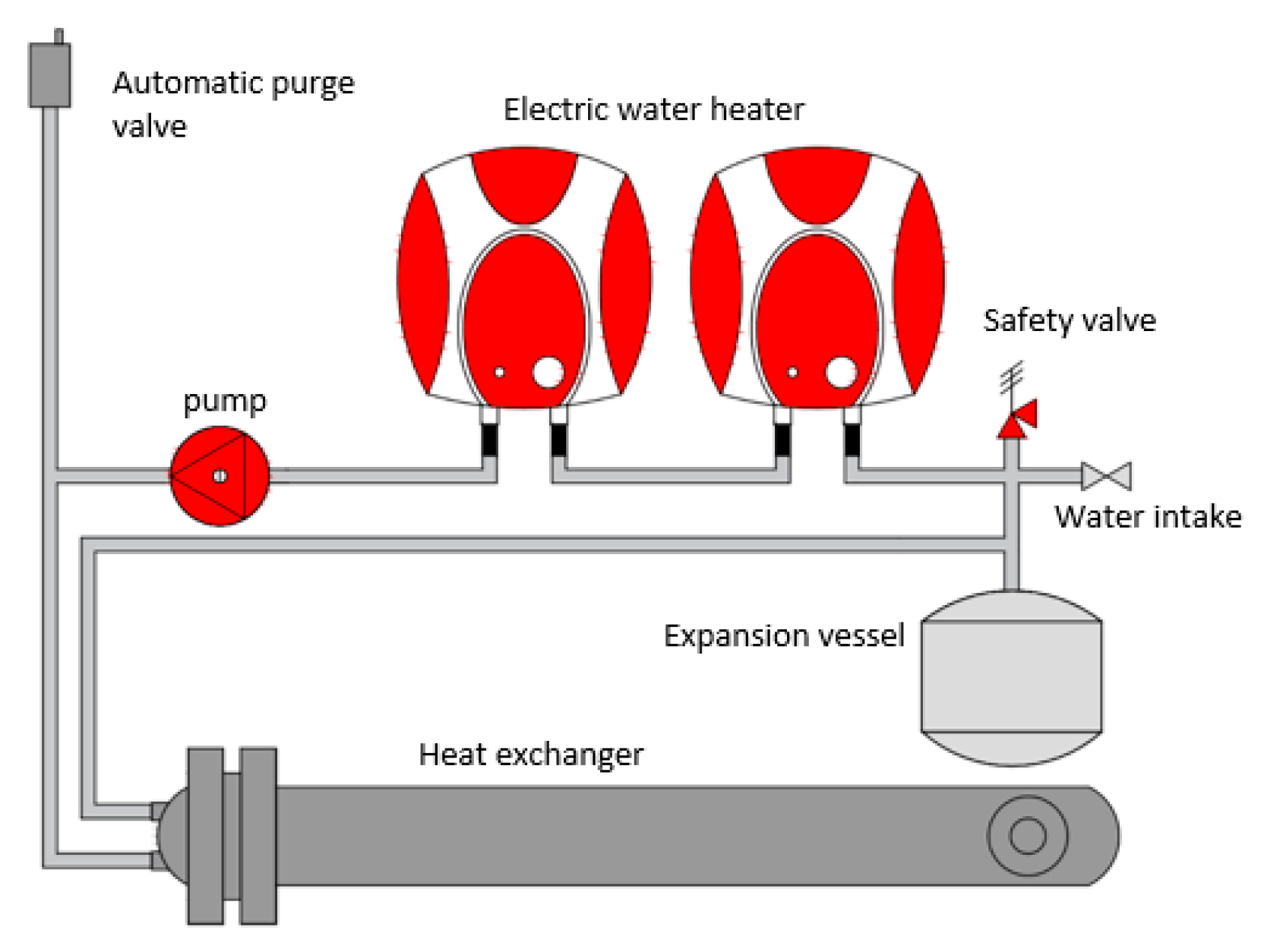
The control house was placed on a shipping container built on a 40 mm thick sandwich panel with external dimensions of 4 × 2.5 × 2.5 m (length × width × height). This container was provided with a lateral door at one end. Devices were installed in the control house for biogas flow measurement, analysis, and evacuation control
The transfer of liquids was carried out by a main pump, a LFC Model LH 40/10, which was installed in the control house. Other installed components were the following: a SUICALSA Model IC26046LB08 tube exchanger of stainless steel for providing the heat necessary to keep the desired temperature of digestion; PVC pipes (DN 75, PN 6 Bar) with coating 3 cm thick insulator; two CEPEX Model 4186 3-way electric rotary valves (denoted as V1 and V2); and three manually operated 3-way valves (denoted as VM1, VM2 and VM3) all made of PVC. The V1 and V2 rotary valves allowed the selection of different pipeline routes to carry out several tasks of the process. The manually operated 3-way valves, VM1 and VM2, were used for select the direction of flow inside the digester. The third manual valve, VM3, was used for selecting the type of incoming material to the reactor. This valve selects the suction site of the main pump, either the pretreatment unit or the auxiliary intake, e.g., to carry out inoculation. The locations of the different valves are schematized in Figure 3.
The different combinations for positioning of the V1 and V2 valves changed the configuration of the system to carry out different tasks. Two main settings were established, i.e., the mixing-heating configuration and the purge-feeding configuration. The mixing-heating configuration was intended for recirculating the digester liqueur and attaining homogenization. As can be seen in Figure 4, the piping system connected the outlet port of the digester, through valves V1 and V2, with the aspiration of the main pump, which pumped the digestate up to the inlet port of the anaerobic reactor, going through the exchanger. Mixing and heating took place by recirculating the digester liqueur to keep the temperature at the desired conditions. By means of the three-way valves with manual actuation, VM1 and VM2, the circulation flow through ports A, B, C, and D was configured (see Figure 4). This pumping circuit was used indistinctly for both recirculation and digester temperature control. These two tasks only differed in terms of the circulation of hot water through the primary circuit of the exchanger when it was necessary to increase the temperature of the reactor in order to keep the mesophilic conditions stable.
Configuring the system for performing the purging of digestate and feeding tasks was more complex than the configuration for performing mixing and circulating tasks, as it required different sequential configurations of the V1 and V2 electric rotary valves. The process of purging digestate and feeding sequence is described below, along with the different functions of the piping and valve systems. Figure 5 shows the different sequences.
Firstly, the V1 value opens, thus connecting the bottom of the digester with the auxiliary tank, causing circulation of digestate to this later unit without causing pressure variations, because these two tanks are connected on the top. Once the desired purge volume is reached, the V1 valve closes (see Figure 5). Subsequently, the V2 valve opens connecting the pretreatment unit with the digester through the main pump. The activation of the main pump is done simultaneously with the activation of the auxiliary pump. The main pump introduces the feeding material coming from the hydrolysis tank into the digester. The feeding volume added to the reactor depends on the amount previously retrieved from the digester and the volume needed for adjusting the reactor filling level. As the feeding occurs the auxiliary pump housed in the auxiliary tank evacuates its content into the digestate storage tank. This simultaneous operation of the system pumps minimizes pressure variations inside the digester. Once the feeding procedure is finished, the valve system is reconfigured for the mixing-heating mode.

2.6. Heating System

The heating system was composed of two electric heaters for the production of hot water. The electric heaters were both GABARRÓN Model GTS 10 1500 W. The system was also provided with a GRUNDFOS Model 25-40 45 W heating pump and a SUICALSA Model IC2604LB08 stainless steel tube heat exchanger. All these elements were installed in the control house. As a safety device, a 5 L expansion vessel with an automatic purge valve and overpressure safety valve was installed. The water intake resulted in both filling and adjusting the pressure of the heating circuit (see Figure 6).
The working principle of the heating system was as follows: The hot water produced in the electric water heaters is recirculated through the system by the heating pump. When the hot water reaches the primary circuit of the exchanger, it transfers its thermal energy to the digested material that is circulating through the secondary circuit, in turn moved by the main pump. Once the water gives up its thermal energy, it leaves the exchanger to be heated again by the electric water heaters.

2.7. Biogas Piping Line
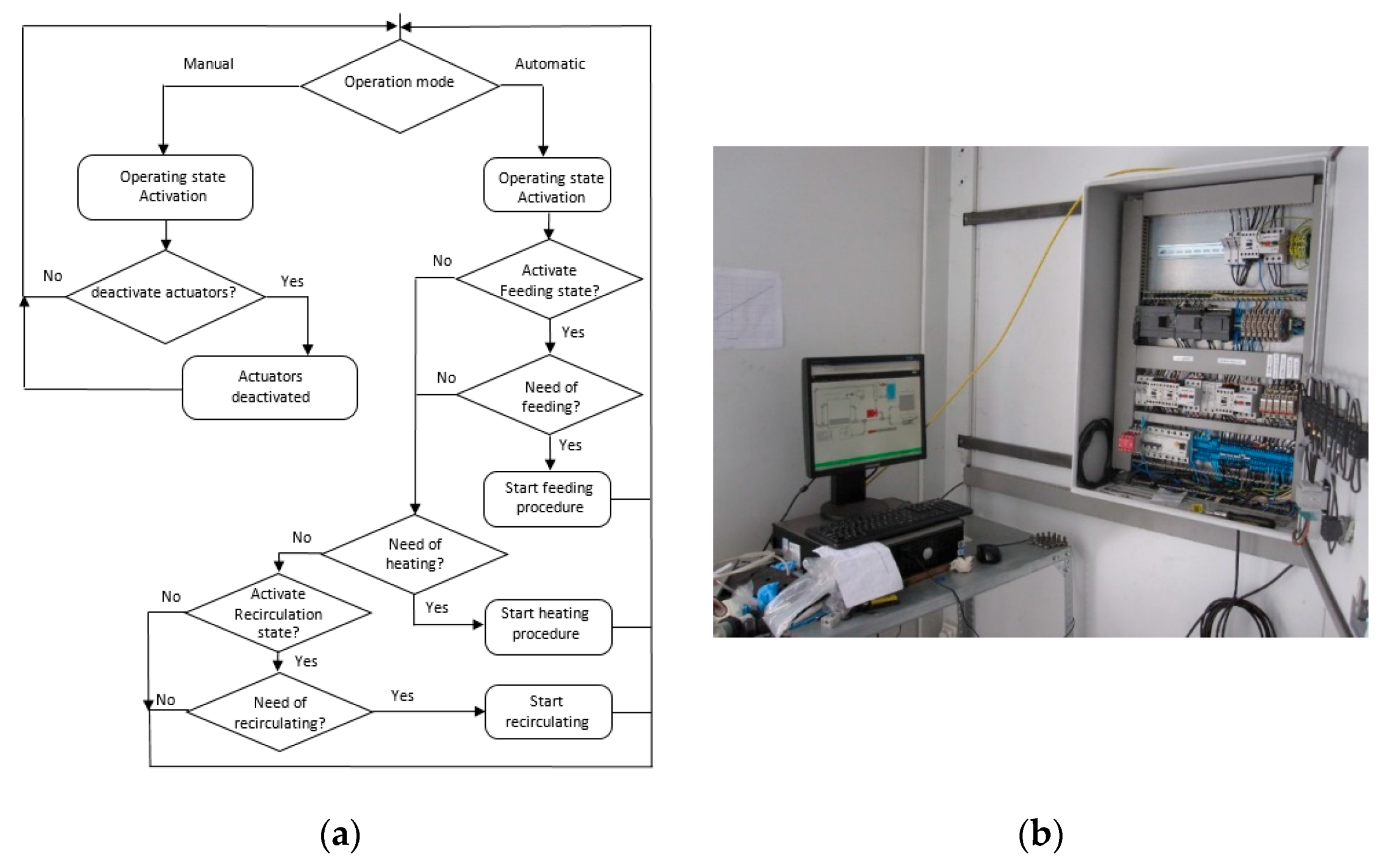
The biogas line contained devices for flow measurement and analysis. The biogas piping was made up of a PVC pipe (DN 32, PN 6 Bar), a condensate trap, a solenoid valve (BURKERT Model 0742 with ATEX certificate), and a commercial gas flow meter ELSTER Model BK-G4 (volumetric flow range of 40–6000 L/h). The biogas was evacuated through the dome of the digester. The biogas pipeline contained a condensate trap to eliminate water vapor. The condensate trap also had an overpressure valve, both grouped in the same device, which reduced the water content of the biogas and prevented biogas accumulation inside the digester in the event of malfunctioning of the biogas evacuation system. At the outlet of the condensate trap, the biogas met the evacuation solenoid valve, so that, when it opened, the biogas circulated through the gas flow meter.
A biogas sample port was located between the evacuation solenoid valve and the condensate trap. This intake supplied biogas continuously to the gas analysis system. The components of this system were a power supply unit, a peristaltic pump DOSIPER Model C1R with a flow capacity of 4.5 L/h, a filter CAMOZZI Model N204-F00, a biogas conditioning block, and the sensors BLUESENS Models BCP-O2 and BCP-CH4 for analyzing oxygen and methane, respectively.
The peristaltic pump maintained a constant flow of biogas to the analyzer through the filter to prevent the admission of particles and condensates into the analysis line. The biogas conditioning block was composed of a refrigerator module Peltier RS Model RH 1.4-32-06L cell with a power of 13 W attached at one side to a cylindrical copper block (diameter of 125 mm, height of 150 mm) and on the other to a small radiator. The block included a rolled copper tube, 8 mm in diameter and about 2 m long, that served as a heat exchanger of the biogas line. It was also externally insulated with polyurethane foam so that water vapor was condensed and prevented from reaching the measurement sensors.
Sensors were placed in series after the biogas conditioning unit. The oxygen sensor had a measurement range between 0 and 25% by volume and using a galvanic cell. The methane sensor had a range between 0 and 100% concentration, and it is an infrared gas analyzer. The sensors both had an accuracy error less than 0.2% of the full scale of the measurement and a 4–20 mA signal transmitter that delivered its reading to the control unit for recording.

2.8. Control Unit

The control panel housed the electrical safety switchgear and the power and control switchgear of the different actuators. The command switchgear was subordinated to a SIEMENS Model Step 7-200 PLC, which had two additional analog input modules connecting the different sensors and control algorithms. The control panel also offered the possibility of manually selecting the control mode of the different actuators. These selectors had three positions, i.e., automatic, zero, and manual. In automatic mode, the system had total control over actuators. In zero mode, the actuator was always deactivated, regardless of the signal from the control system, whereas, in manual mode, the actuator was always activated.
The control PC had a SCADA system for monitoring and configuring the process. This system also recorded data of different process variables and events that could have taken place during operation. The control PC allowed one to have remote access to the SCADA system, and therefore the plant could be operated online, when internet access was available.

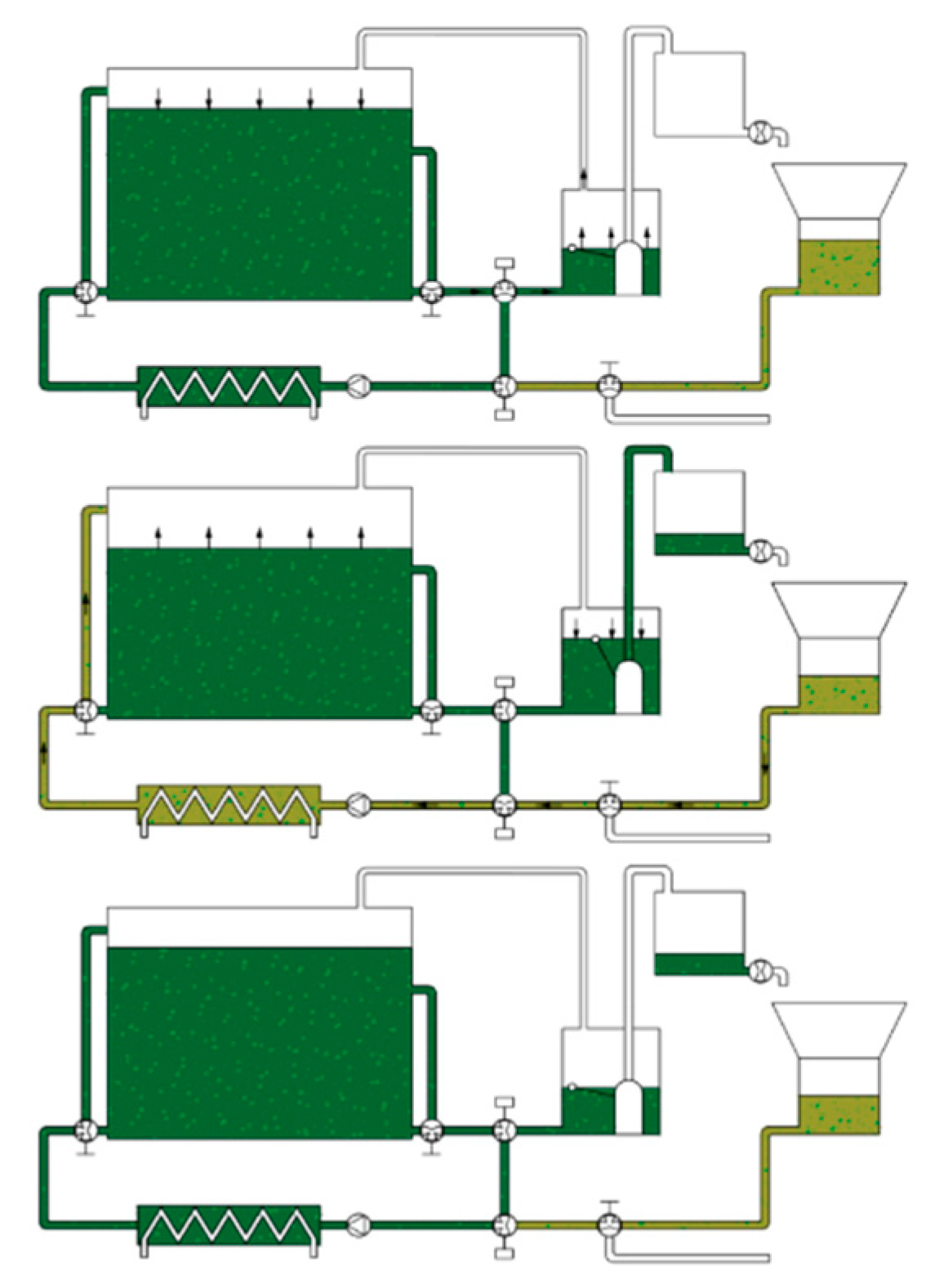
2.9. Description of the Control Algorithm

The control system had two operating modes which were denoted as manual and automatic mode. These modes could be selected by the user from the SCADA main screen. There were four other states which were established and denoted as operation, feeding, heating, and recirculating. These states controlled the process and were responsible for activating and deactivating the different actuators based on the value of process variables and setpoints. This action, as well as controlling the different modes, could be performed from the main SCADA screen.
In manual mode, the control system deactivated the states of feeding, heating, and recirculating, whilst the operating state remains active. Setting the system in this mode allowed the user to take control over the status of all actuators from the main SCADA screen. However, the extraction of biogas, which was a task inherent to the operating state, remained active for safety reasons to avoid biogas pressure accumulating inside the digester.
When the control system was in automatic mode, the activation of the other states was subject to the values reached by process variables and parameters. There was a priority range in the activation of the different states. Operation status was always active; thus, process variables could always be visualized on the SCADA screen. Figure 7 represents the control flow chart of the process.
The operation state was considered to be the basic state of all the control systems. During this state, only process variables were observable, and extraction of biogas was executed. This state was always active to allow the user to visualize variables in real time and make sure that biogas was always extracted from the reactor, disregarding the activation of any other state.
Biogas extraction was governed by two parameters which were “minimum pressure” and “maximum pressure”. When the pressure inside the digester was greater than the “maximum pressure” setpoint, the gas solenoid valve opened. When the pressure was less than the “minimum pressure” value, it closed. The extraction of biogas was, therefore, a cyclical process that was reflected in the evolution of pressure within the digester as a saw-tooth profile.
The feeding state, allowed one to feed substrate to the reactor by means of the activation/deactivation sequence of different actuators. The feeding state was activated when this status was enabled, based on process parameters associated with the time of start-up of this feeding procedure. It was a cyclic recipe with a set duration and a sequence that could be programmed to be repeated every 8, 12, or 24 h, and thus a user could establish the desired hydraulic retention time.
During the heating state, the digester liqueur was heated to keep the process temperature at the desired value. Activation of the heating state depended on the previously set temperature of the digester. When the temperature measured by the sensor located in the digester was below this setpoint (taking into account a hysteresis value of 0.5 °C), the control system activated the heating state. When the temperature exceeded the setpoint (also taking into account this hysteresis value) the status was deactivated. Activating this heating state also implied activation of both the recirculation pump and the heating pump. It also indirectly activated the electric water heaters, because during normal operation there was a decrease in the temperature of the water stored in the heating water tanks.
During the recirculating state, the digestate was stirred by recirculation to promote mixing and homogenization.

2.10. Evaluation of Digester Performance

During the start-up of the prototype, different tests were carried out to establish the accuracy of the system for measuring volumes. The result of these tests determined that deviations with values greater than 10 L were not found, and there were no errors found regarding accuracy when measuring values greater than 50 L associated with the upper limit of the operating range. This supposed an error in the determination of the volume of less than 1%. Tests were also carried out to determine the errors associated with temperature measurements when registering the temperature inside the digester. Errors of around 0.1 °C were obtained when the system worked at a temperature range of 32–38 °C and errors increased to a value of 1.3 °C when the temperature was in the range of 52–58 °C. Likewise, pressure reading tests were carried out in the dome of the digester, and deviations in readings of less than 4% were always obtained, when working at the established pressure (5 mbar). Similarly, leaks of the digester were tested by applying pressures between 12 and 15 mbar, which resulted in leakage rates of less than 0.2 L/min, which translated, in practical terms, into zero flow rate at the working pressure (a pressure value lower than 5 mbar). This behavior made feasible the assumption of neglecting the leakage for the digestion system when running at the established pressure and for an expected production flow of about 300 L/h.
Measurements of pH, total and volatile solids (TS and VS), along with ammonia nitrogen, which was measured via selective electron, were quantified following APHA standard methods [22]. Substrate samples were randomly taken, and the quartering method was used to obtain a representative sample. Ten substrate samples were obtained for elemental analysis. Elemental analysis of carbon, hydrogen, and nitrogen were performed using A LECO CHN-600 apparatus.
Mass balance calculations were performed using manual data recording from sampling of the pretreatment and reactor unit to compare the evolution of VS in the process. Calculations were performed based on the non-steady state regime with no exit stream available in order to increase the volume of the reactor from the initial inoculation volume up to the working volume.

3. Results

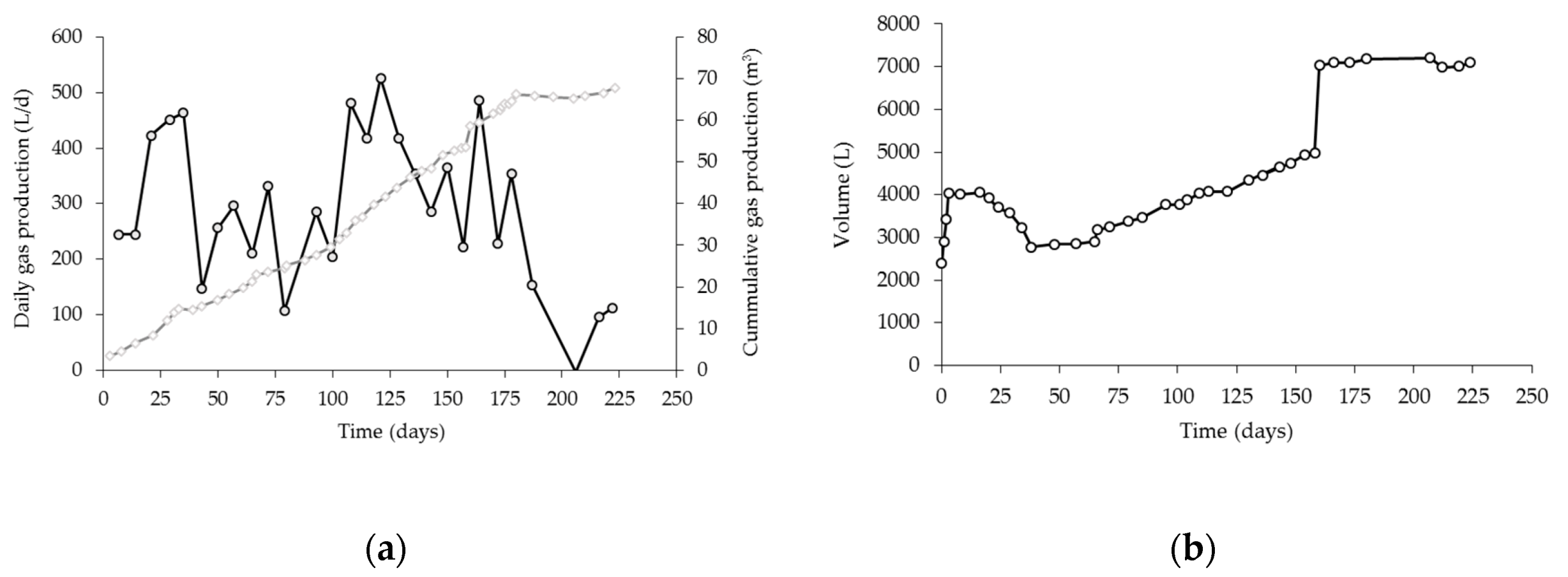
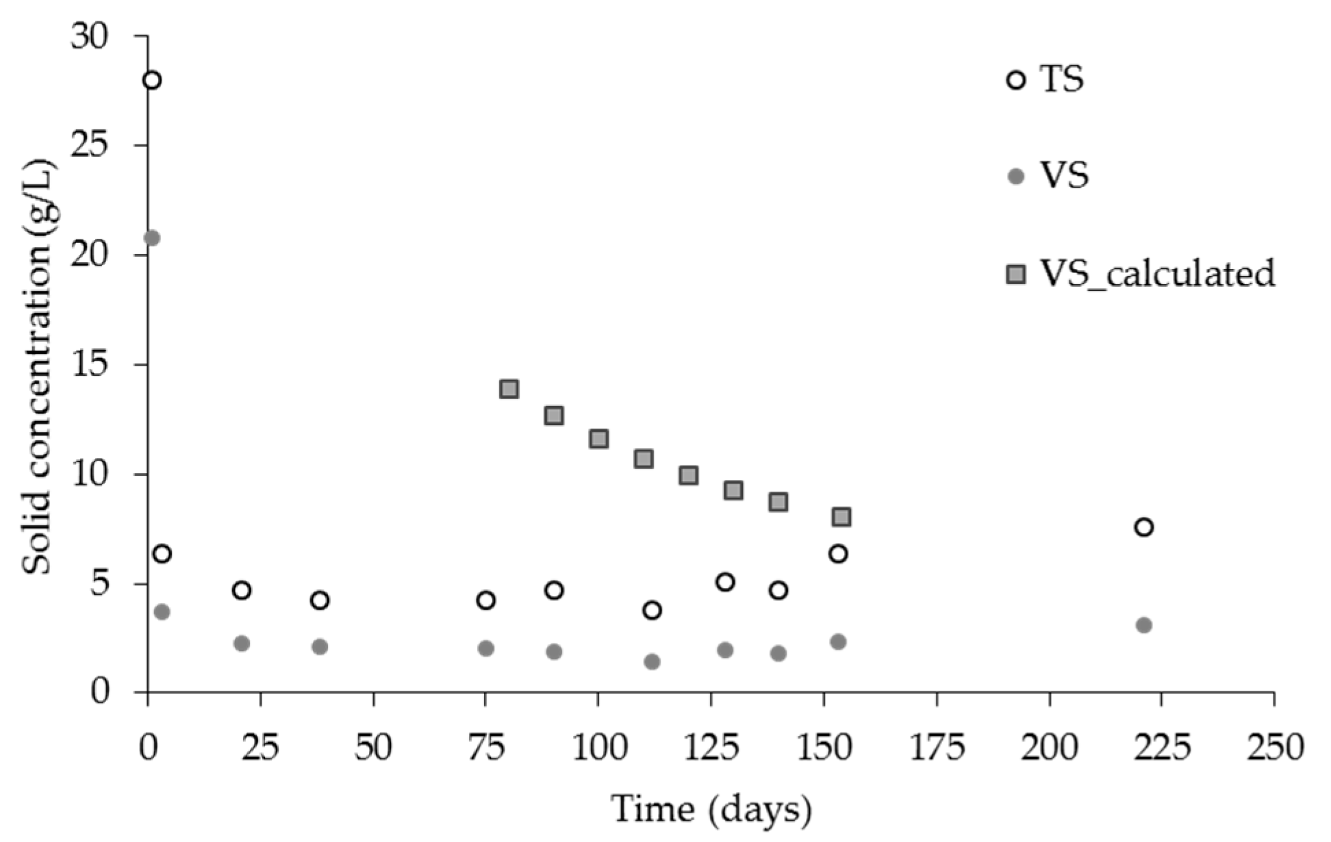
Evaluating System Start-Up

During the start-up of the prototype, several tests were carried out to establish conditions for the correct working of the unit and power supply system, of which it is worth mentioning the need of evaluating the maximum dilution ratio of the substrate. The type of substrate used in this prototype was restricted by project constraints. The prototype treated food wastes and was initially designed to handle an expected average solid content of 150 g TS/kg. This material was obtained from a local company dedicated to the production of fourth range fruit and vegetable products. The solid content of the organic material finally treated was about 12% (TS). The material available for the initial testing of the prototype came from a fourth range company dedicated to the processing of salads and packaged fruit. This material presented a variable composition based on the seasonal availability of some components but, in general, its main components were pineapple peels and cores, wastes from fruits (mango, apple), and vegetables. Table 1 presents composition and analysis of the waste used as a substrate.
The grinding system had the ability to work without the external addition of water, but the pumping unit required the addition of this fluid to facilitate pumping. The grinding of organics resulted in a stream which did not flow easily, thus, dilution was necessary to avoid clogging of pipes and ducts (grinding of food wastes is shown Figure 8). It was necessary to carry out grinding and pumping tests using a material similar to that expected during the different seasons of the year. The waste generated was characterized by having a significant pineapple peel content during the warmer months, making it difficult to pump it when the solids content exceeds 5%. The plant’s original design initially considered the use of digestate as media for the hydrolysis tank once the reactor was fully operational. This type of configuration eliminates the need for adding water and facilitates the hydrolysis of this material. The aim was to reduce digestion time and problems associated with pumping of the feed. Initially, a ratio of 250 kg waste/m3 of dilution water was used for evaluating pumping performance but this ratio was not successful and a final ratio of 200 kg/m3 was established.
The initial pumping tests of the unit and working of the prototype led to the clogging of the heat exchanger, as can be observed in Figure 9. The grinding of the material resulted in particle size and texture which was not easily pumped. The initial operation of the hydrolysis unit was performed using dilution water. Here, we report on the performance under this condition. However, once the digestion process was fully operational, clogging problems were circumvented thanks to the addition of digestate into the hydrolysis tank of the pretreatment unit instead of using dilution water. This change in working conditions facilitated hydrolysis and caused fast liquefaction and acidification of organics and particles. The active anaerobic microflora, which presented in the digested material, helped to further reduce the particle size when digestate was added to the hydrolysis tank of ground organics.
It was found that running the process was possible when the hydrolysis tank contained a proportion of 50–65% (w/w) of organics. However, when pineapple peel wastes were in a proportion higher than 35% (referred to composition of the fresh substrate), then the recipe should contain values of organics as low as 40–25% (w/w, considering wet weight of organics). These restrictions implied that the VS concentration in the feeding material was between 7 and 9% and fell to 3.5–5.5%, when pineapple peels were the main component of the substrate.
The automatic operation of the unit required the determination of volumes associated with the supply of feeding material to the digester and associated with the withdrawal from this reactor to the digestate storage tank. These parameters were denoted as “purge volume correction” and “feed volume correction”, and therefore the control system was able to adjust volumes transferred during the opening and closing times of the valves. For the reactor working with a volume of 7200 L, corrections of 32 and 21 L were obtained for the parameters “purge volume correction” and “feed volume correction”, respectively.
It was also necessary to establish the pumping flow of the prototype. For this, several pumping tests were carried out to measure the pressure drop of the hydraulic circuit based on the results obtained and the characteristics of the pump provided by the manufacturer (LFC [23]). Taking into account the configuration of the prototype, it was assumed that the main pressure drop was mostly due to the heat exchanger since the pressure drop of the pumping head was low. The average pumping flow measured through the system was 247 L/min (14.8 m3/h).
The anaerobic reactor was initially inoculated with digestate obtained from an anaerobic digester from a wastewater treatment plant located near Madrid. This inoculum had an initial pH value of 7.5 units. The reactor was inoculated to 1/3 of its capacity and we expected that the whole volume of the reactor would be completed with the addition of fresh substrate. However, this operation took excessive time, and therefore was abandoned, as described later. The inoculum had an initial TS concentration of 28 g/L and a VS content of 55% (VS/TS). The ammonium content of this inoculum was 450 mg/L. Feeding of the substrate was performed at a low organic loading rate because of the acid characteristics of the material associated with their high carbohydrate content and because partial hydrolysis of this material in the hydrolysis tank resulted in a feeding substrate with a pH value between 4.5 and 5.5 units. The initial operation of the plant was performed adding substrate, but it did not allow the exit of digestate from the reactor in an attempt to rapidly increase the digestion volume. The initial days of plant operation were mainly dedicated to correcting flows, avoiding pipe obstructions, and assuring that the desired working conditions could be attained. Therefore, the continuous feeding of the reactor unit started on day 70.
Since the start-up of the reactor did not consider enough volume of digestate to aid in the hydrolysis process, acidification of the anaerobic reactor was a major inconvenience when trying to increase the organic loading rate, because the dilution water in the hydrolysis tank resulted in feeding a suspension with a low pH into the reactor and, consequently, a greatly disturbed pH of the digestion unit.
Figure 10 shows the gas production and reactor level variation when working at a variable volume of the reactor in an attempt to increase the maximum allowed volume. This strategy was abandoned, as previously stated, because the rate of volume increase was extremely low due to the low organic loading rate fed into the reactor. This can be easily observed in Figure 10b. The graph represents the period of volume variation and gas production associated with this stage. The graphs also show the rate of gas production; for the period from 30 to 180 days, the rate of gas production presented a value of 0.367 m3/d (obtained by approximating a linear regression to the dataset). This gas production rate translates into a methane specific production of 232 L/kg VS. Regarding the level variation in the reactor unit, this parameter presented a rate of 19.7 L/d (also obtained from the linear approximation of level data derived, in this case, from Figure 10b.
The organic loading rate (OLR) applied to the reactor was particularly low given the acid pH of the organic material, therefore the loading was initially set at 0.95 kg VS/d. This value was initially intended to be gradually increased as part of the start-up strategy but due to the low pH levels measured during the operation (values between 6.5 and 6.8 during the experimental period) of the reactor, the feeding rate was set constant without any possibility of modification, and therefore without risking a higher decrease in pH. With this low OLR, and given the low nitrogen content of the feeding material, the reactor was deprived of enough essential nutrients, and therefore VS destruction was attained in a non-steady state manner, thus the initial content of VS in the reactor was 15.4 g/L, and this value was greatly reduced thereafter. The measured VS content obtained from the sample was 3.1 g/L. However, this value seemed extremely low and it was suspected that settling of solids inside the digester was taking place. For this reason, the mass balance was established for the global system and for the VS content in the reactor.
On the one hand, when considering the global mass balance of the reactor unit, assuming that the mass variation was associated with the introduction of the feeding stream and the production of biogas, this balance is written as follows:
d M T d t = q i n ρ i n q o u t ρ o u t M ˚ b i o g a s
where M T represents the mass content of the reactor, q i n and q o u t represent the volumetric flow in and out of the system in units of L/d. In this case, the reactor received the feeding stream but also a level variation was allowed, and no exit stream was established, therefore this exit stream had a zero flow. The density of the streams is ρ i n and ρ o u t . M ˚ b i o g a s is the gas production rate. Considering that the density of the reactor liqueur is about the same as that of the incoming stream, the rate of volume variation is represented by Equation (2) as follows:
d V d t = q i n M ˚ b i o g a s ρ
where ρ is the density of the reactor liqueur. This rate of volume ( d V /   d t , denoted as V˚) variation is coincident with the slope of Figure 10b and it is coincident with the value obtained from the amount of biogas measured and the incoming volumetric flow to the reactor. Thus, the value of 19.7 L/d for the volume variation was accurate.
On the other hand, when considering the mass balance of VS for the reactor unit, the following expression was obtained:
d M V S d t = q i n V S i n q o u t V S o u t r × V
The total mass of VS contained in the reactor is represented by M V S . As in the previous balance, the subscript in and out represents the incoming and outlet stream. The destruction rate of VS is assumed to be equivalent to the biogas production rate, considering that biogas produced comes exclusively from VS available in the reactor. Given that the mass of VS contained in the reactor is calculated from Equation (4):
M V S   =   V ×   V S
The VS balance can be rewritten as follows:
V S × V ˚ + V d ( V S ) d t =   q i n × V S i n   M ˚ b i o g a s
Therefore, the expected VS variation in the reactor is given by Equation (6), taking into account that for the period evaluated (84 days) the initial VS concentration was 15.4 g/L.
V d ( V S ) d t =   q i n V S i n V ˚ × ( V S )   M ˚ b i o g a s
Given that the daily volume variation and the biogas production rate are also known, along with the volume profile inside the digester, as a function of time, then
V   =   V 0 + V ˚ × t
The VS profile can be obtained from Equation (8) as follows:
V S i V S d ( V S ) q i n V S i n M ˚ b i o g a s V ˚ × ( V S ) = t 0 t d t V 0 + V ˚ × t
From the VS mass balance of the reactor operating under non-steady state conditions, the VS concentration should be 8.0 g/L given the rate of destruction of VS, which was easily estimated from the cumulative gas production and the evaluation period. On the basis of the measurements and mass balance estimations, a comparison between the expected evolution of VS and that obtained from measurement ports can be represented in Figure 11.
The gas accumulated, and represented in Figure 10a, comes from the assimilation of the organic material fed into the reactor and also from the VS content of the inoculum, and therefore explaining the decrease observed in VS content from the calculated data using the mass balance equations. This assumption was corroborated by the decrease in ammonium nitrogen in the reactor. The inoculum had an initial value of 450 mg/L of ammonium, but this value was decreased to 120 mg/L on day 154. This performance has been reported in the literature by Molinuevo-Salces et al. [24] who reported an increase in biodegradability at a higher C/N ratio. In the present case, the degradation of the substrate was also accompanied by the degradation of cellular components, due to the deficient nitrogen composition of the substrate.
On the basis of these results, the strategy of increasing reactor volume was abandoned, and reinoculation was performed using, in this case, an inoculum coming from an anaerobic reactor treating sewage sludge and slaughterhouse waste which was characterized by high ammonium content. The reinoculation corresponded to the level increment, presented in Figure 10b, on day 158. With this new loading, the reactor completed its working volume, the plant was rapidly operational, and recycling of digestate was now allowed which highly improved pH conditions inside the digester and, most importantly, the performance of hydrolysis in the pretreatment unit. Thus, after reinoculation, the ammonium content in the reactor increased to an average value of 6500 mg/L. The results of this second stage were presented by González et al. [25] along with the energy balance of the reactor prototype. The life cycle assessment of this treatment option when dealing with the valorization of wastes derived from the fourth range sector can be found in González et al. [26]. Figure 12 shows the small-scale prototype installed at the facility.
The actions taken to improve the performance of the plant were the recirculation of digestate, the increment in the OLR applied, and modifications of the heating system to keep digestion temperature at the desired range. The addition of digestate to the hydrolysis tank helped in avoiding severe drops in the pH of the hydrolyzed material acting as a buffer and improving solubilization of organics. The control effect on pH also helped in avoiding pH excursion inside the digester when the feeding procedure took place. Given that mixing of the reactor was performed by means of the recirculation pump, the mixing time was expected to be high, thus, the relevance in avoiding the introduction of a highly acidified material into the reactor. Our reported results correspond to the fed-batch mode of the plant, therefore no digestate was produced during this experimental stage. However, once full inoculation of the plat was carried out, the digestion unit was fully operational and a digestate stream was obtained from the reactor. This digestate was used as irrigation liquid of composting piles.

4. Conclusions

In this manuscript, the description of a small-scale digestion plant intended for decentralized operation was reported, along with the strategies for the prototype start-up and performance of the plant during the fed-batch mode. The prototype was initially conceived to treat fruit and vegetable wastes. These organics were characterized by having high methane potential but the fast acidification attained in the hydrolysis tank led to a stream with low pH, greatly affecting the digestion system. The strategy of increasing the volume of the reactor by using the fed-batch mode was inadequate given the acid character of the feeding material which caused a high risk of decreasing the pH of the system close to inhibitory levels. Increasing the volume of the reactor from an initial point where only a third of this reactor was inoculated resulted in an extremely long procedure. The low nitrogen content of the feeding material also resulted in excessive destruction of volatiles, and therefore the solid content of the digestate obtained was extremely low. Although all the problems associated with the low organic rate applied, the prototype reported a specific methane production of 232 L/kg VS.
The prototype was fully operational when the inoculation of the total volume of the reactor was carried out. In this way, a sufficient amount of digestate was available to successfully run the hydrolysis unit and the anaerobic reactor, thereby allowing recirculation of the digestate back to the hydrolysis reactor and serving as a measure for controlling pH drops. Other aspects that need to be improved are the increase in the organic load along with the heating system and recirculation process that excessively increases the electricity demand of the plant.

Author Contributions

Conceptualization, X.G. and D.B.; methodology, R.G., D.B.; software, R.G.; validation, R.G. and D.B.; formal analysis, J.G.-A. and X.G.; investigation, J.G.-C.; resources, X.G.; data curation, J.G.-C. and J.G.-A.; writing—original draft preparation, X.G. and R.G.; writing—review and editing, D.B. and J.G.-A.; visualization, J.G.-C.; supervision, X.G.; project administration, X.G. and D.B.; funding acquisition, X.G. All authors have read and agreed to the published version of the manuscript.

Funding

This research was funded through Ministerio de Economía y Competitividad, grant numbers FEDER UNLE15-EE-3070 and IPT-2012-0144-120000.

Acknowledgments

Judith González-Arias would like to thank the Junta de Castilla y León (Consejería de Educación) fellowship, Orden EDU/1100/2017, co-financed by the European Social Fund. The authors wish to thank the collaboration of personal working with the companies Comapitol S.L and Biomasa Peninsular where the prototype was initially installed and tested.

Conflicts of Interest

The authors declare no conflict of interest.

References

  1. Habagil, M.; Keucken, A.; Sárvári Horváth, I. Biogas Production from Food Residues—The Role of Trace Metals and Co-Digestion with Primary Sludge. Environments 2020, 7, 42. [Google Scholar] [CrossRef]
  2. Loughrin, J.; Antle, S.; Sistani, K.; Lovanh, N. In Situ Acoustic Treatment of Anaerobic Digesters to Improve Biogas Yields. Environments 2020, 7, 11. [Google Scholar] [CrossRef] [Green Version]
  3. Rai, C.L.; Rao, P.G. Influence of sludge disintegration by high pressure homogenizer on microbial growth in sewage sludge: An approach for excess sludge reduction. Clean Technol. Environ. 2009, 11, 437. [Google Scholar] [CrossRef]
  4. Hong, E.H.; Park, J.G.; Lee, B.; Shi, W.Q.; Jun, H.B. Improvement of Waste Dehydrated Sludge for Anaerobic Digestion through High-Temperature and High-Pressure Solubilization. Energies 2019, 13, 88. [Google Scholar] [CrossRef] [Green Version]
  5. Ahmed, B.; Aboudi, K.; Tyagi, V.K.; Álvarez-Gallego, C.J.; Fernández-Güelfo, L.A.; Romero-García, L.I.; Kazmi, A.A. Improvement of anaerobic digestion of lignocellulosic biomass by hydrothermal pretreatment. Appl. Sci. 2019, 9, 3853. [Google Scholar] [CrossRef] [Green Version]
  6. Li, R.; Tan, W.; Zhao, X.; Dang, Q.; Song, Q.; Xi, B.; Zhang, X. Evaluation on the methane production potential of wood waste pretreated with NaOH and Co-digested with pig manure. Catalysts 2019, 9, 539. [Google Scholar] [CrossRef] [Green Version]
  7. Calabrò, P.S.; Fazzino, F.; Folino, A.; Paone, E.; Komilis, D. Semi-continuous anaerobic digestion of orange peel waste: Effect of activated carbon addition and alkaline pretreatment on the process. Sustainability 2019, 11, 3386. [Google Scholar] [CrossRef] [Green Version]
  8. Tian, X.; Trzcinski, A. Effects of physico-chemical post-treatments on the semi-continuous anaerobic digestion of sewage sludge. Environments 2017, 4, 49. [Google Scholar] [CrossRef] [Green Version]
  9. Zhen, X.; Zhang, X.; Li, S.; Li, M.; Kang, J. Effect of micro-oxygen pretreatment on gas production characteristics of anaerobic digestion of kitchen waste. J. Mater. Cycles Waste Manag. 2020, 1–7. [Google Scholar] [CrossRef]
  10. Loughrin, J.; Lovanh, N. Aeration to improve biogas production by recalcitrant feedstock. Environments 2019, 6, 44. [Google Scholar] [CrossRef] [Green Version]
  11. Martínez, E.J.; Rosas, J.G.; González, R.; García, D.; Gómez, X. Treatment of vinasse by electrochemical oxidation: Evaluating the performance of boron-doped diamond (BDD)-based and dimensionally stable anodes (DSAs). Int. J. Environ. Sci. Technol. 2018, 15, 1159–1168. [Google Scholar] [CrossRef]
  12. García-Cascallana, J.; Borge-Díez, D.; Gómez, X. Enhancing the efficiency of thermal hydrolysis process in wastewater treatment plants by the use of steam accumulation. Int. J. Environ. Sci. Technol. 2019, 16, 3403–3418. [Google Scholar] [CrossRef]
  13. Piñas, J.A.V.; Venturini, O.J.; Lora, E.E.S.; del Olmo, O.A.; Roalcaba, O.D.C. An economic holistic feasibility assessment of centralized and decentralized biogas plants with mono-digestion and co-digestion systems. Renew. Energy 2019, 139, 40–51. [Google Scholar] [CrossRef]
  14. Rajendran, K.; Murthy, G.S. Techno-economic and life cycle assessments of anaerobic digestion–A review. Biocatal. Agric. Biotechnol. 2019, 20, 101207. [Google Scholar] [CrossRef]
  15. Álvarez-de Prado, L.; Simón-Martín, D.; Diez-Suárez, A.M.; Blanes-Peiró, J.J.; González-Martínez, A. Optimal Sizing and Location of Co-Digestion Power Plants in Spain through a GIS-Based Approach. Environments 2018, 5, 137. [Google Scholar] [CrossRef] [Green Version]
  16. Kayode, O.F.; Luethi, C.; Rene, E.R. Management Recommendations for Improving Decentralized Wastewater Treatment by the Food and Beverage Industries in Nigeria. Environments 2018, 5, 41. [Google Scholar] [CrossRef]
  17. Levaggi, L.; Levaggi, R.; Marchiori, C.; Trecroci, C. Waste-to-Energy in the EU: The Effects of Plant Ownership, Waste Mobility, and Decentralization on Environmental Outcomes and Welfare. Sustainability 2020, 12, 5743. [Google Scholar] [CrossRef]
  18. Antizar-Ladislao, B.; Turrion-Gomez, J.L. Decentralized energy from waste systems. Energies 2010, 3, 194–205. [Google Scholar] [CrossRef] [Green Version]
  19. Bruni, C.; Akyol, Ç.; Cipolletta, G.; Eusebi, A.L.; Caniani, D.; Masi, S.; Colón, J.; Fatone, F. Decentralized Community Composting: Past, Present and Future Aspects of Italy. Sustainability 2020, 12, 3319. [Google Scholar] [CrossRef] [Green Version]
  20. de Kraker, J.; Kujawa-Roeleveld, K.J.; Villena, M.; Pabón-Pereira, C. Decentralized valorization of residual flows as an alternative to the traditional urban waste management system: The case of peñalolén in santiago de chile. Sustainability 2019, 11, 6206. [Google Scholar] [CrossRef] [Green Version]
  21. Ferronato, N.; Torretta, V. Waste mismanagement in developing countries: A review of global issues. Int. J. Environ. Res. Public Health 2019, 16, 1060. [Google Scholar] [CrossRef] [Green Version]
  22. APHA. Standard Methods for the Examination of Water and Wastewater; APHA: Washington, DC, USA, 2005; ISBN 9780875530475. [Google Scholar]
  23. LFC. Electrobombas Sumergibles Para Agua Residuales. 2013. Available online: https://www.bombashasa.com/es/productos/lfc/electrobombas-sumergibles-para-aguas-residuales/ (accessed on 10 January 2020).
  24. Molinuevo-Salces, B.; Gómez, X.; Morán, A.; García-González, M.C. Anaerobic co-digestion of livestock and vegetable processing wastes: Fibre degradation and digestate stability. Waste Manag. 2013, 33, 1332–1338. [Google Scholar] [CrossRef]
  25. González, R.; Hernández, J.E.; Gómez, X.; Smith, R.; González Arias, J.; Martínez, E.J.; Blanco, D. Performance evaluation of a small-scale digester for achieving decentralised management of waste. Waste Manag. 2020, 118, 99–109. [Google Scholar] [CrossRef]
  26. González, R.; Rosas, J.G.; Blanco, D.; Smith, R.; Martínez, E.J.; Pastor-Bueis, R.; Gómez, X. Anaerobic digestion of fourth range fruit and vegetable products: Comparison of three different scenarios for its valorisation by life cycle assessment and life cycle costing. Environ. Monit. Assess. 2020, 192, 551. [Google Scholar] [CrossRef]
Figure 1. Schematic representation of the pretreatment unit and its components.
Environments 07 00078 g001
Figure 2. Small decentralized digester for the treatment of food wastes. (a) Shipment of the digester once finished to be installed at the testing site; (b) Digester configuration and port positioning.
Environments 07 00078 g002
Figure 3. Description of components of the decentralized digestion plant and distribution of valve location and auxiliary equipment.
Environments 07 00078 g003
Figure 4. Schematic representation of reactor liqueur circulation when the mixing-heating configuration is activated.
Environments 07 00078 g004
Figure 5. Schematic representation of the feeding procedure to avoid abrupt changes in pressure.
Environments 07 00078 g005
Figure 6. Representation of the configuration of the heating system designed for keeping the temperature of anaerobic reactor.
Environments 07 00078 g006
Figure 7. (a) Control flow chart of the process; (b) Control panel of the prototype located in the control house.
Environments 07 00078 g007
Figure 8. Pictures representing feeding to the grinding unit and pretreatment tank having the function of storing the substrate and attain hydrolysis of food waste.
Environments 07 00078 g008
Figure 9. (a) Heat exchanger located in the control house; (b) Dismantling of heat exchanger due to clogging problems.
Environments 07 00078 g009
Figure 10. (a) Daily gas production and the cumulative gas curve obtained from the start-up of the prototype operating at variable volume; (b) Volume profile obtained under the fed-batch strategy.
Environments 07 00078 g010
Figure 11. Representation of the solid concentration of the reactor liqueur obtained from measurements and values calculated using mass balance equations for the period between 70 and 154 days.
Environments 07 00078 g011
Figure 12. The small-scale prototype. The photograph shows the control house, the pretreatment unit, and the anaerobic reactor.
Environments 07 00078 g012
Table 1. Characteristics of the substrate used in the testing of the small-scale anaerobic reactor.
ComponentMass Composition (%)
Pineapple wastes30–60
Mango peels and discarded waste10–15
Fruit wastes (including apple wastes)10–12
Vegetables and pumpkin wastes15–25
Solid content of the mixture(g/kg)
TS123–135
VS115–124
Elemental analysis(%)
Carbon42.2 ± 0.7
Hydrogen6.0 ± 0.4
Nitrogen1.5 ± 0.1

