
Laboratory Investigation of Hydraulic Parameters on Inclined Drop Equipped with Fishway Elements

 ,
,  ,
,  ,
,  ,
,  ,
,
Abstract
:1. Introduction
2. Materials and Methods
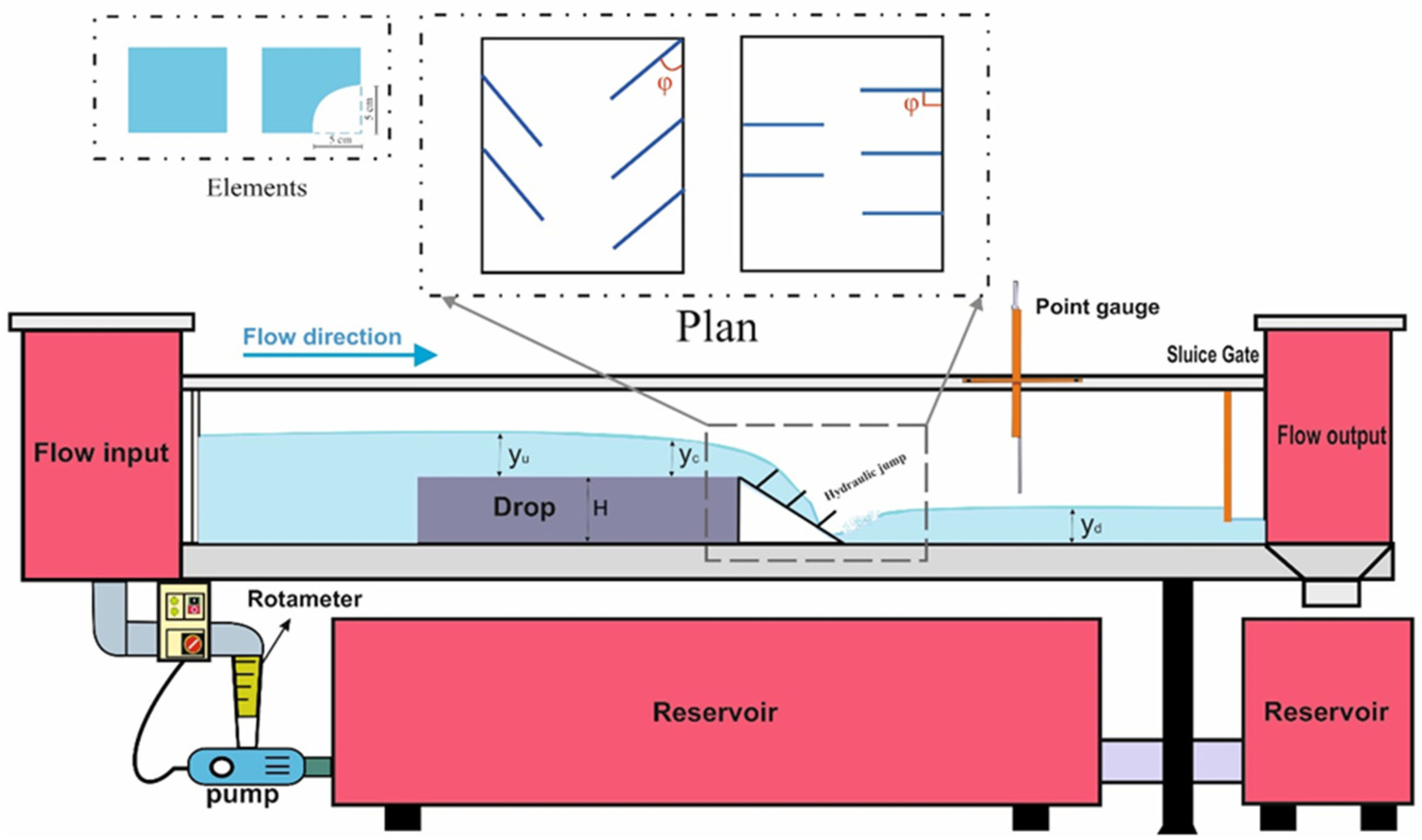
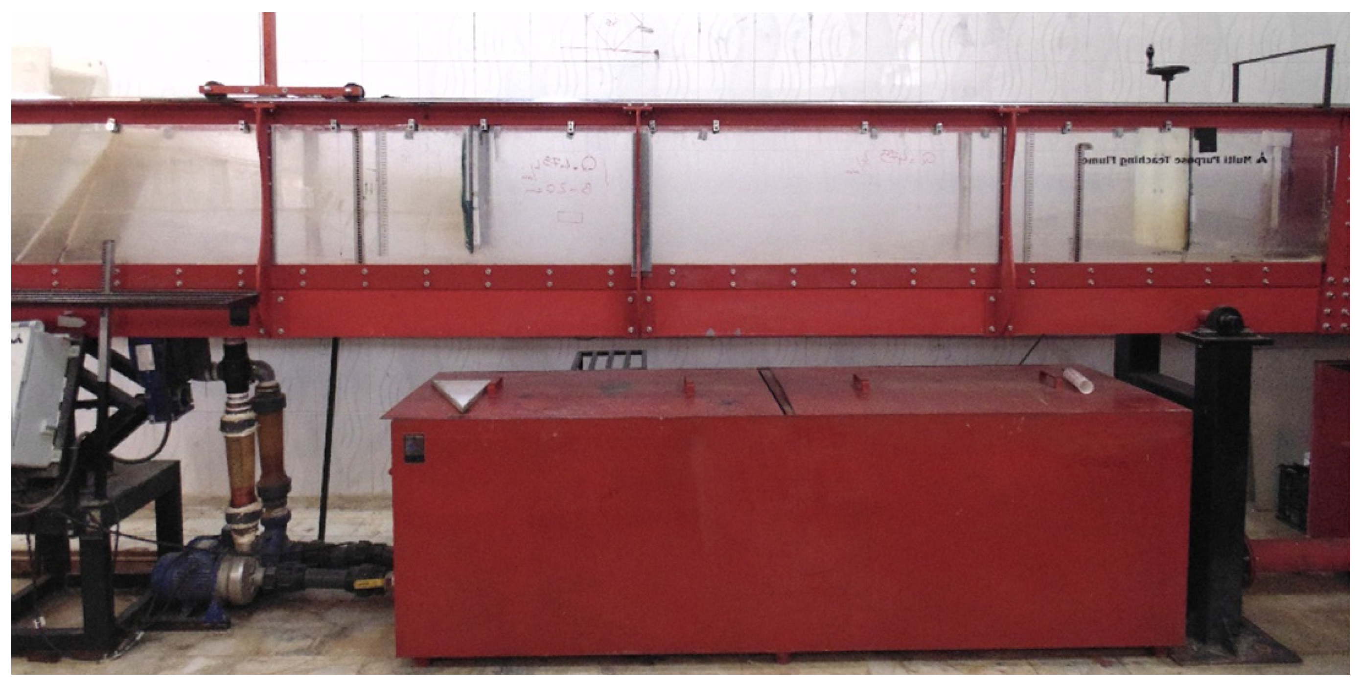
2.1. Experimentally Equipment
2.2. Dimensional Analysis
2.3. Specific Energy Equations and Evaluation Criteria
2.4. Study’s Limitations
3. Results and Discussion
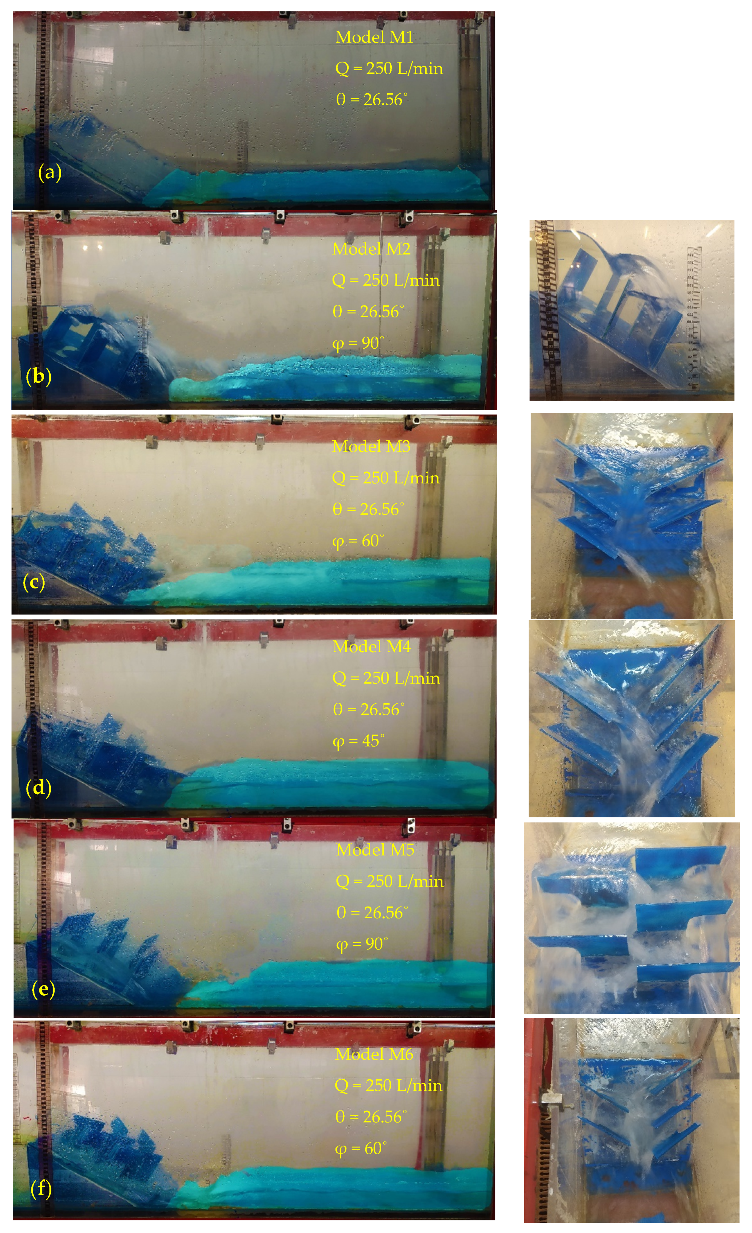
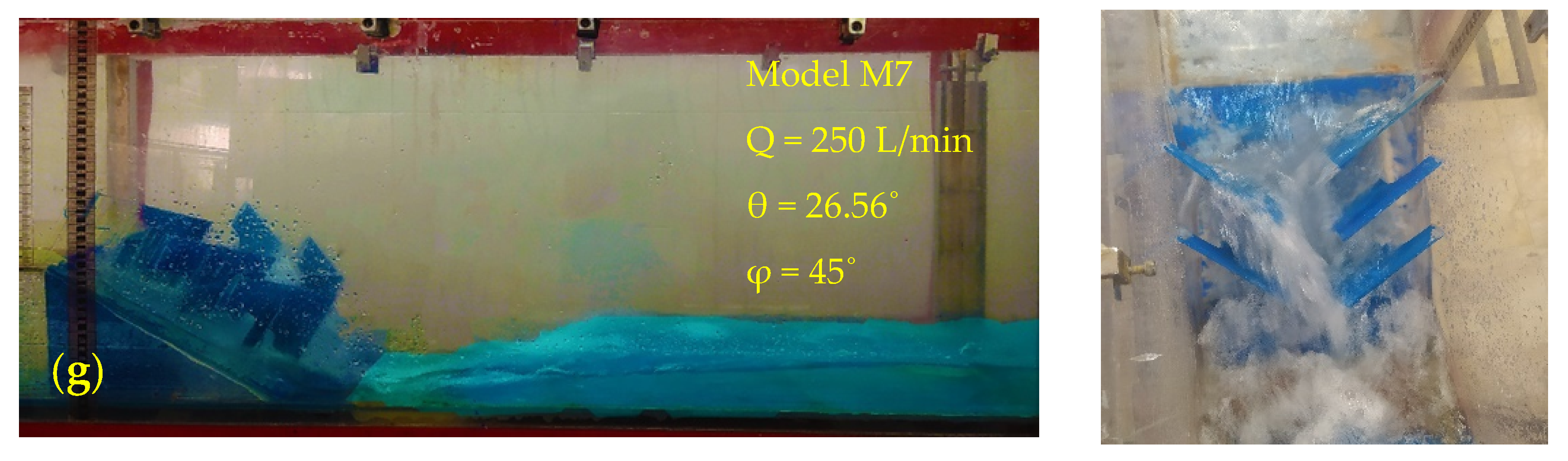
3.1. Experimentally Observations
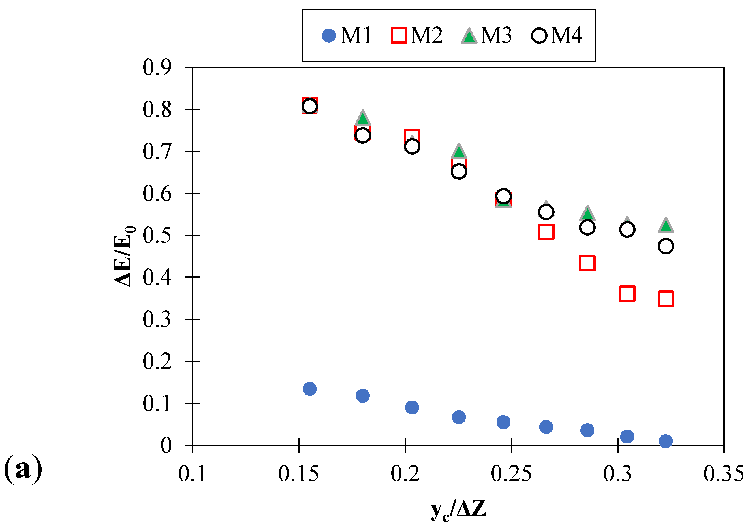
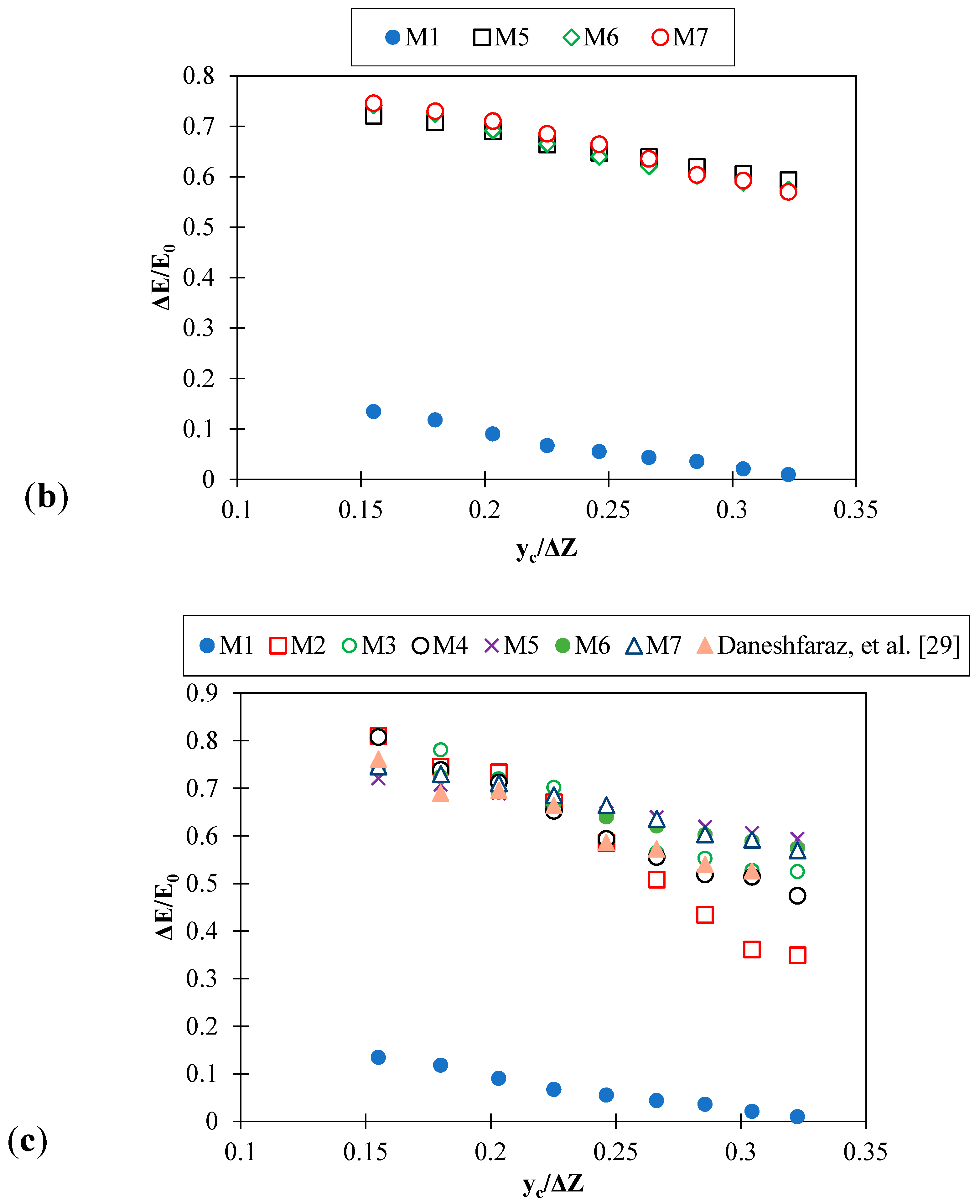
3.2. Energy Dissipation
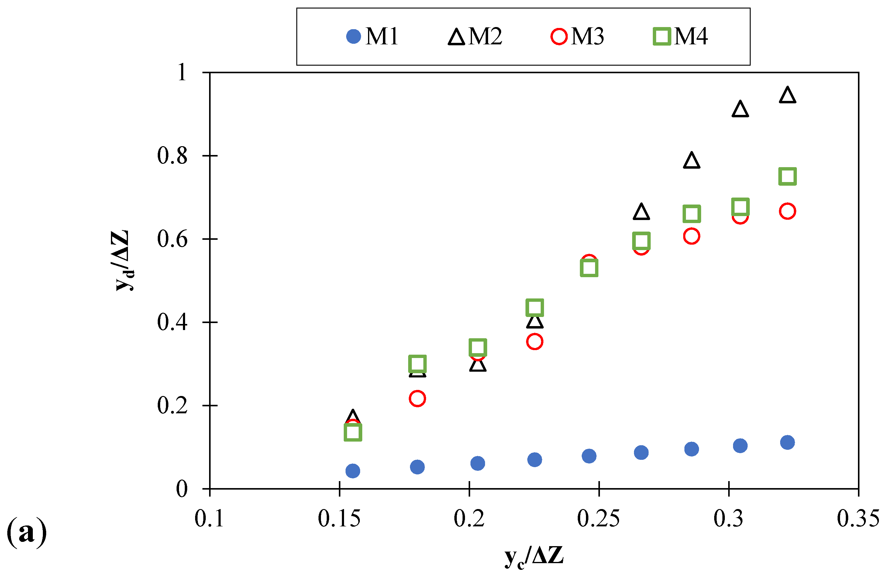
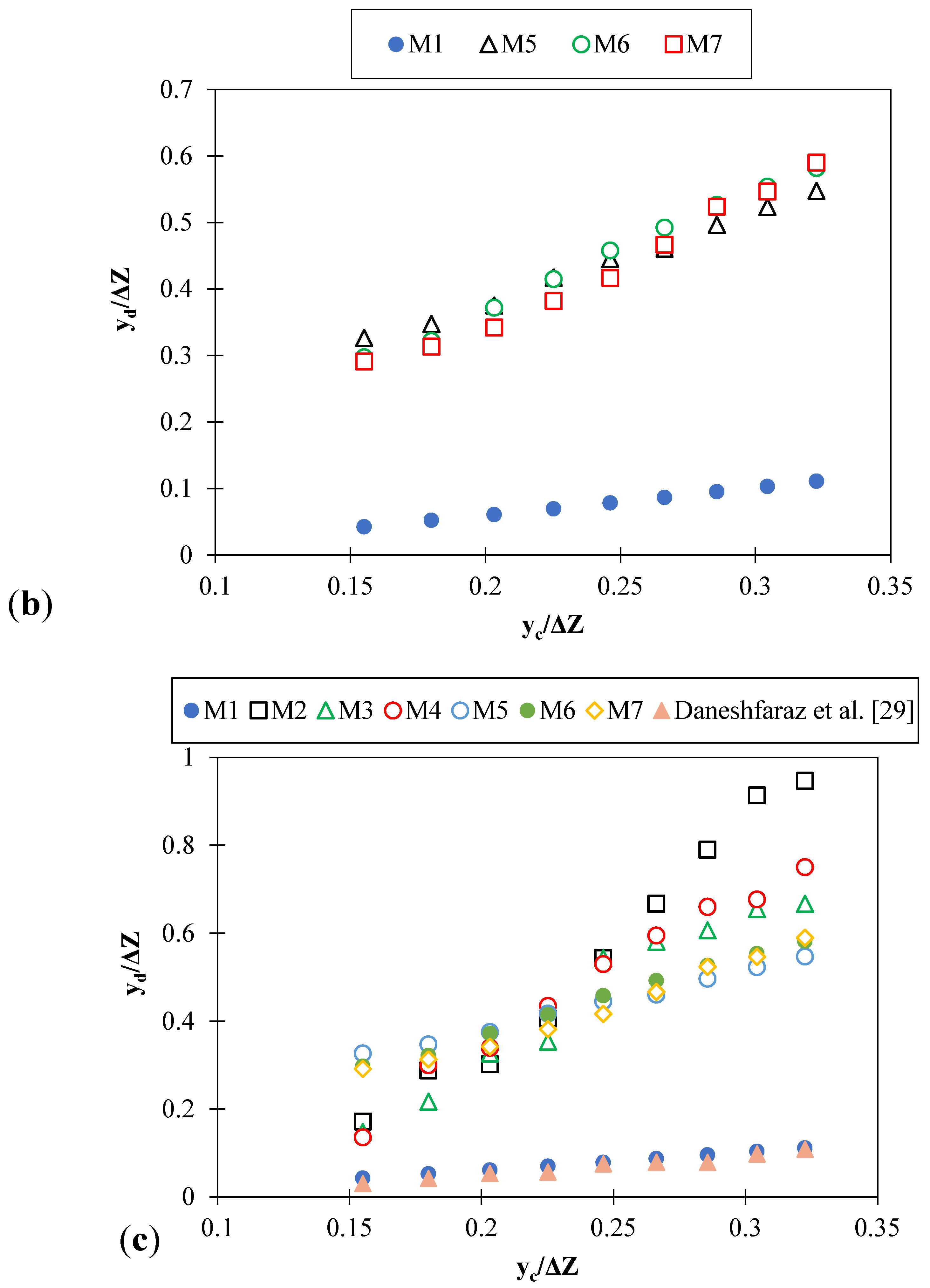
3.3. Relative Downstream Depth
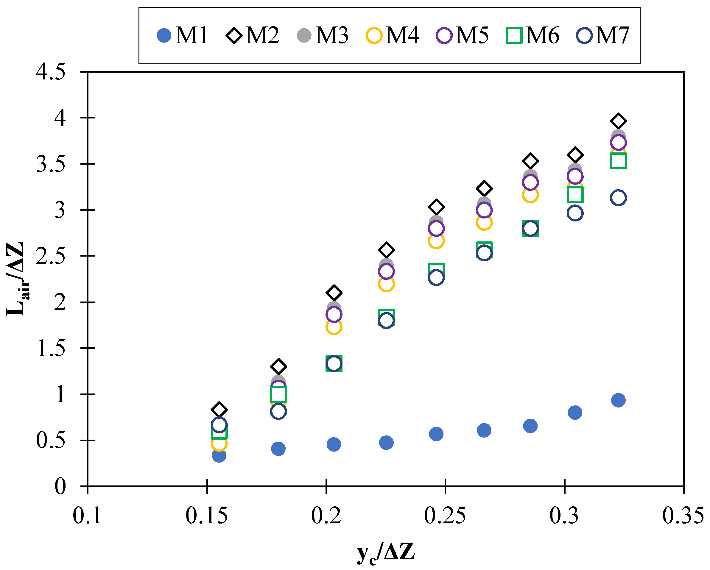
3.4. Relative Aeration Length
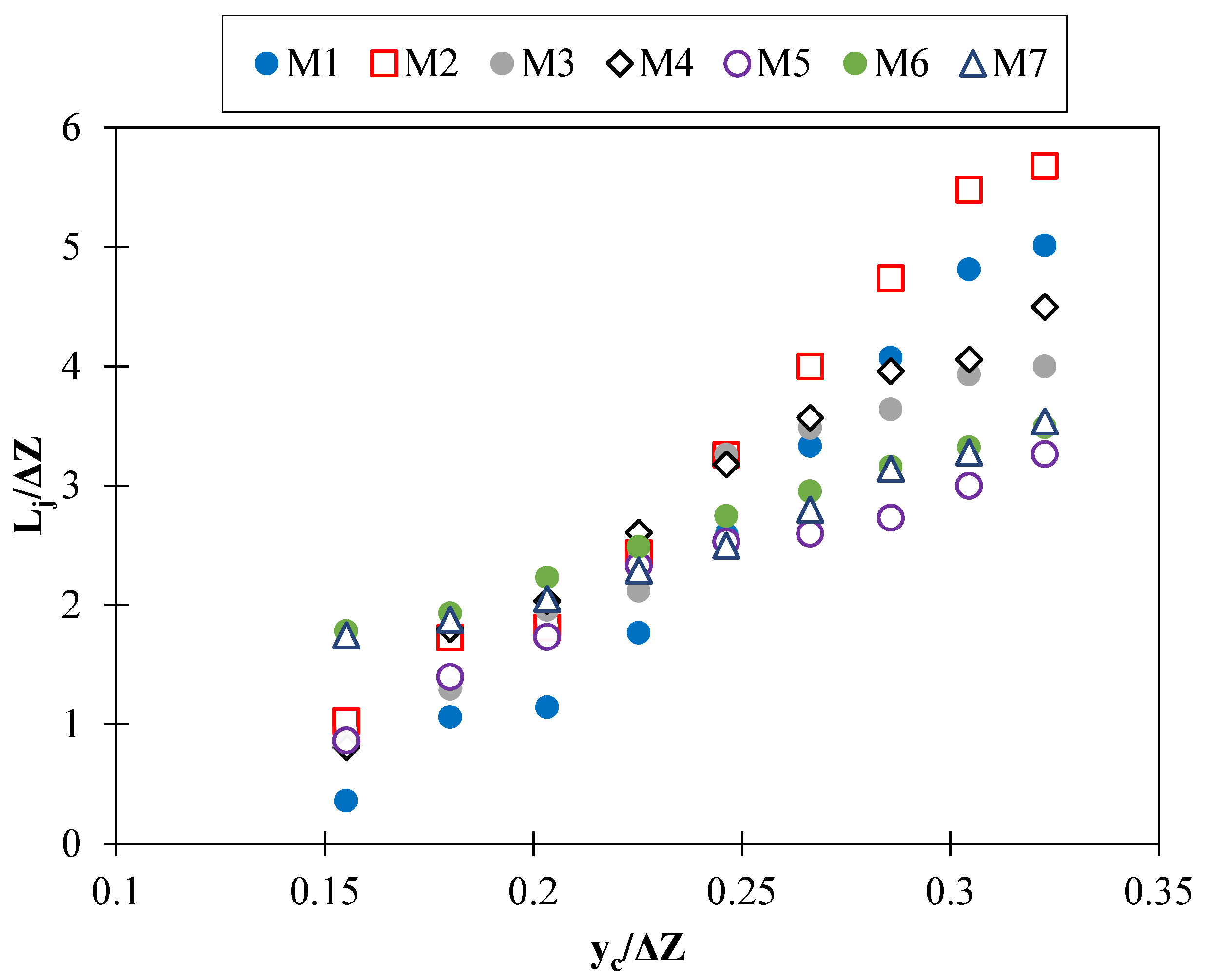
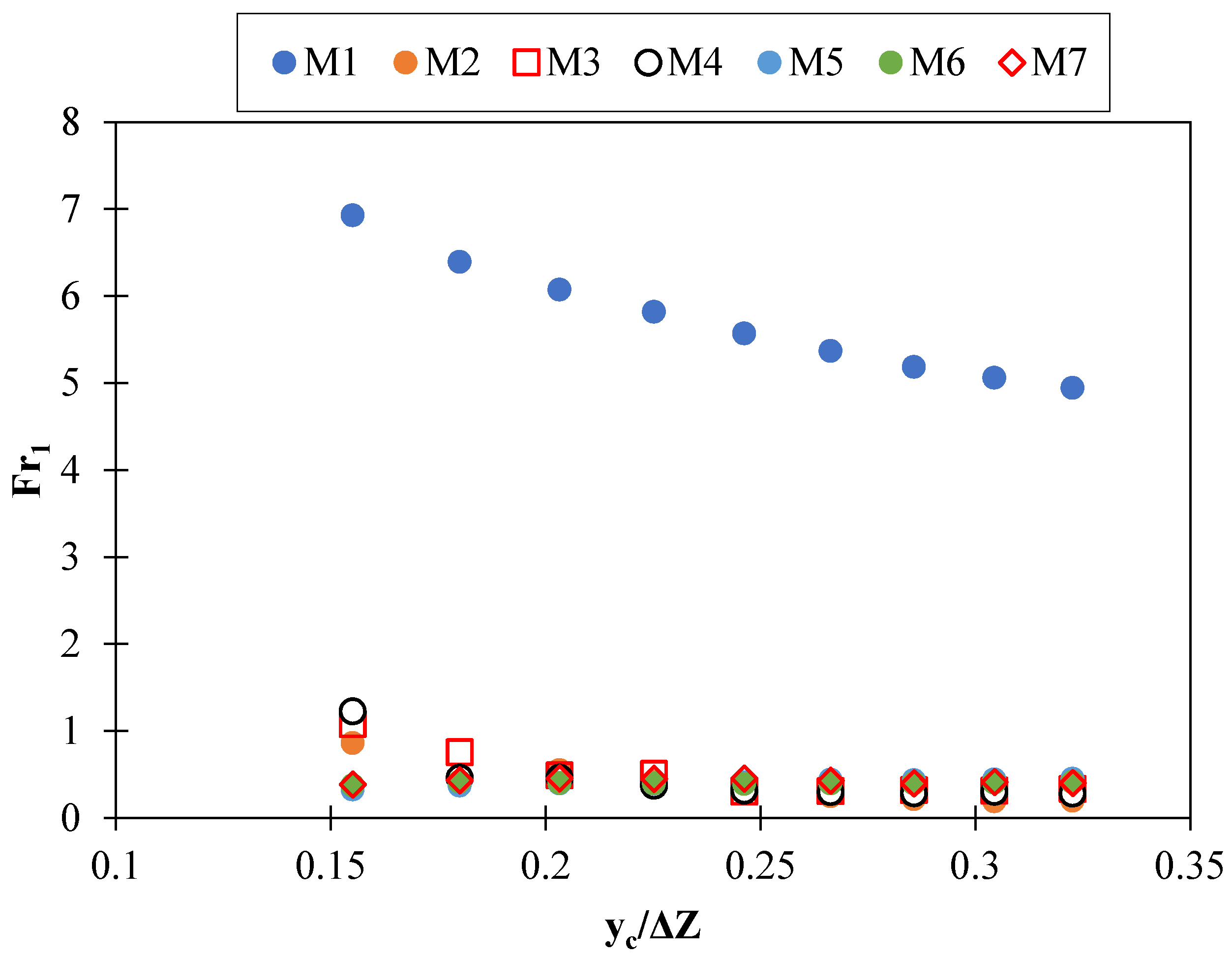
3.5. Relative Length of Hydraulic Jump and Downstream Froude Number
3.6. Experimental Equations
4. Conclusions
- By increasing the relative critical depth parameter, the relative energy dissipation decreases. The simple inclined drop has the lowest energy dissipation, and the M7 model has the highest energy dissipation. Adding fishway elements to a simple inclined drop increases the flow energy dissipation by an average of 88%, which is a significant value.
- Model M2 has the maximum length of flow aeration. By reducing the angle of the element, the amount of air entering the water also decreases. Increasing the amount of aeration and energy dissipation of the flow reduces the outlet flow downstream. It prevents scouring and foaming problems of the channel. In addition to the positive economic impact, increasing aeration is of particular importance on aquatic animals.
- For all models, the relative depth of the downstream is directly related to the relative critical depth. The use of fishway elements has significantly increased the downstream depth. The M2 model has the highest relative depth of the downstream overall.
- The use of fishway elements on the inclined drop structure causes more energy to be lost from the flow and a hydraulic jump to occur inside the stilling basins. On the other hand, these elements significantly reduce the Froude number for all relative critical depths, which is an essential point in the design of inclined drops.
- The advantages of using fishway elements in comparison with other dissipating structures, in addition to environmental considerations, are also economic considerations. Some dissipators, such as screens and stilling basins, are expensive costs to build. However, in addition to environmental considerations, fishway structures have a meager construction cost. They have also helped a lot in energy dissipation.
Author Contributions
Funding
Institutional Review Board Statement
Informed Consent Statement
Data Availability Statement
Acknowledgments
Conflicts of Interest
References
- Jager, H.I.; Chandler, J.A.; Lepla, K.B.; Van Winkle, W. A Theoretical Study of River Fragmentation by Dams and its Effects on White Sturgeon Populations. Environ. Biol. Fishes 2001, 60, 347–361. [Google Scholar] [CrossRef]
- Kuriqi, A.; Pinheiro, A.N.; Sordo-Ward, A.; Bejarano, M.D.; Garrote, L. Ecological impacts of run-of-river hydropower plants—Current status and future prospects on the brink of energy transition. Renew. Sustain. Energy Rev. 2021, 142, 110833. [Google Scholar] [CrossRef]
- Andersson, E.; Nilsson, C.; Johansson, M. Effects of river fragmentation on plant dispersal and riparian flora. Regul. Rivers Res. Manag. Int. J. Devoted River Res. Manag. 2000, 16, 83–89. [Google Scholar] [CrossRef]
- van Puijenbroek, P.J.; Buijse, A.D.; Kraak, M.H.; Verdonschot, P.F. Species and river specific effects of river fragmentation on European anadromous fish species. River Res. Appl. 2019, 35, 68–77. [Google Scholar] [CrossRef]
- Heino, J.; Virkkala, R.; Toivonen, H. Climate change and freshwater biodiversity: Detected patterns, future trends and adaptations in northern regions. Biol. Rev. 2009, 84, 39–54. [Google Scholar] [CrossRef]
- Moss, B.; Hering, D.; Green, A.J.; Aidoud, A.; Becares, E.; Beklioglu, M.; Bennion, H.; Boix, D.; Brucet, S.; Carvalho, L.; et al. Climate Change and the Future of Freshwater Biodiversity in Europe: A Primer for Policy-Makers. Freshw. Rev. 2009, 2, 103–130. [Google Scholar] [CrossRef]
- Belletti, B.; Garcia de Leaniz, C.; Jones, J.; Bizzi, S.; Börger, L.; Segura, G.; Castelletti, A.; van de Bund, W.; Aarestrup, K.; Barry, J.; et al. More than one million barriers fragment Europe’s rivers. Nature 2020, 588, 436–441. [Google Scholar] [CrossRef]
- Lucas, M.C.; Bubb, D.H.; Jang, M.H.; Ha, K.; Masters, J.E. Availability of and access to critical habitats in regulated rivers: Effects of low-head barriers on threatened lampreys. Freshw. Biol. 2009, 54, 621–634. [Google Scholar] [CrossRef]
- Branco, P.; Amaral, S.D.; Ferreira, M.T.; Santos, J.M. Do small barriers affect the movement of freshwater fish by increasing residency? Sci. Total. Environ. 2017, 581, 486–494. [Google Scholar] [CrossRef] [PubMed]
- Bestgen, K.R.; Mefford, B.; Compton, R.I. Mortality and injury rates for small fish passing over three diversion dam spillway models. Ecol. Eng. 2018, 123, 141–150. [Google Scholar] [CrossRef]
- Rytwinski, T.; Algera, D.A.; Taylor, J.J.; Smokorowski, K.E.; Bennett, J.R.; Harrison, P.M.; Cooke, S. What are the consequences of fish entrainment and impingement associated with hydroelectric dams on fish productivity? A systematic review protocol. Environ. Evid. 2017, 6, 1–9. [Google Scholar] [CrossRef] [Green Version]
- Clay, C.H. Design of Fishways and Other Fish Facilities; CRC Press: Boca Raton, FL, USA, 2017. [Google Scholar]
- Boiten, W. Flow measurement structures. Flow Meas. Instrum. 2002, 13, 203–207. [Google Scholar] [CrossRef]
- Rodríguez, T.T.; Agudo, J.P.; Mosquera, L.P.; González, E.P. Evaluating vertical-slot fishway designs in terms of fish swimming capabilities. Ecol. Eng. 2006, 27, 37–48. [Google Scholar] [CrossRef]
- Romão, F.; Branco, P.; Quaresma, A.L.; Amaral, S.D.; Pinheiro, A.N. Effectiveness of a multi-slot vertical slot fishway versus a standard vertical slot fishway for potamodromous cyprinids. Hydrobiologia 2018, 816, 153–163. [Google Scholar] [CrossRef]
- Rajaratnam, N.; Katopodis, C.; Solanki, S. New designs for vertical slot fishways. Can. J. Civil. Eng. 1992, 19, 402–414. [Google Scholar] [CrossRef]
- Rajaratnam, N.; Van der Vinne, G.; Katopodis, C. Hydraulics of vertical slot fishways. J. Hydraul. Eng. 1986, 112, 909–927. [Google Scholar] [CrossRef]
- Wu, S.; Rajaratnam, N.; Katopodis, C. Structure of flow in vertical slot fishway. J. Hydraul. Eng. 1999, 125, 351–360. [Google Scholar] [CrossRef]
- Puertas, J.; Pena, L.; Teijeiro, T. Experimental approach to the hydraulics of vertical slot fishways. J. Hydraul. Eng. 2004, 130, 10–23. [Google Scholar] [CrossRef]
- Liu, M.; Rajaratnam, N.; Zhu, D.Z. Mean flow and turbulence structure in vertical slot fishways. J. Hydraul. Eng. 2006, 132, 765–777. [Google Scholar] [CrossRef]
- Yagci, O. Hydraulic aspects of pool-weir fishways as ecologically friendly water structure. Ecol. Eng. 2010, 36, 36–46. [Google Scholar] [CrossRef]
- Daneshfaraz, R.; Aminvash, E.; Ghaderi, A.; Kuriqi, A.; Abraham, J. Three-Dimensional Investigation of Hydraulic Properties of Vertical Drop in the Presence of Step and Grid Dissipators. Symmetry 2021, 13, 895. [Google Scholar] [CrossRef]
- Daneshfaraz, R.; Aminvash, E.; Ghaderi, A.; Abraham, J.; Bagherzadeh, M. SVM Performance for Predicting the Effect of Horizontal Screen Diameters on the Hydraulic Parameters of a Vertical Drop. Appl. Sci. 2021, 11, 4238. [Google Scholar] [CrossRef]
- Daneshfaraz, R.; Ghaderi, A.; Di Francesco, S.; Khajei, N. Experimental study of the effect of horizontal screen diameter on hydraulic parameters of vertical drop. Water Supply 2021. [Google Scholar] [CrossRef]
- Wagner, W. Hydraulic model studies of the check intake structure-potholes east canal. Bur. Reclam. Hydraul. Lab. Rep. Hyd. 1956, 411, 7. [Google Scholar]
- Peterka, A.J. Hydraulic Design of Stilling Basins and Energy Dissipators; US Department of the Interior, Bureau of Reclamation: Washington, DC, USA, 1964.
- Bos, M.G.; Replogle, J.A.; Clemmens, A.J. Flow Measuring Flumes for Open Channel Systems; John Wiley & Sons Inc.: New York, NY, USA, 1984; Volume 19, 321p, ISBN Z-0471-80637-4. [Google Scholar]
- Sholichin, M.; Akib, S. Development of drop number performance for estimate hydraulic jump on vertical and sloped drop structure. Int. J. Phys. Sci. 2010, 5, 1678–1687. [Google Scholar]
- Daneshfaraz, R.; Majedi Asl, M.; Bagherzadeh, M. Experimental Investigation of the Energy Dissipation and the Downstream Relative Depth of Pool in the Sloped Gabion Drop and the Sloped simple Drop. Amirkabir J. Civil. Eng. 2021, 53, 4-4. [Google Scholar]
- Daneshfaraz, R.; Bagherzadeh, M.; Ghaderi, A.; Di Francesco, S.; Majedi Asl, M. Experimental investigation of gabion inclined drops as a sustainable solution for hydraulic energy loss. Ain Shams Eng. J. 2021. [Google Scholar] [CrossRef]
- Daneshfaraz, R.; Bagherzadeh, M.; Esmaeeli, R.; Norouzi, R.; Abraham, J. Study of the performance of support vector machine for predicting vertical drop hydraulic parameters in the presence of dual horizontal screens. Water Supply 2020, 21, 217–231. [Google Scholar] [CrossRef]
- Ghaderi, A.; Daneshfaraz, R.; Torabi, M.; Abraham, J.; Azamathulla, H.M. Experimental investigation on effective scouring parameters downstream from stepped spillways. Water Supply 2020, 20, 1988–1998. [Google Scholar] [CrossRef]
- Daneshfaraz, R.; Ghaderi, A.; Akhtari, A.; Di Francesco, S. On the Effect of Block Roughness in Ogee Spillways with Flip Buckets. Fluids 2020, 5, 182. [Google Scholar] [CrossRef]
- Daneshfaraz, R.; Aminvash, E.; Esmaeli, R.; Sadeghfam, S.; Abraham, J.; Vol, E. Experimental and numerical investigation for energy dissipation of supercritical flow in sudden contractions. J. Groundw. Sci. 2020, 8, 396–406. [Google Scholar]
- Ghaderi, A.; Abbasi, S. Experimental and Numerical Study of the Effects of Geometric Appendance Elements on Energy Dissipation over Stepped Spillway. Water 2021, 13, 957. [Google Scholar] [CrossRef]
- Ghaderi, A.; Dasineh, M.; Shokri, M.; Abraham, J. Estimation of Actual Evapotranspiration Using the Remote Sensing Method and SEBAL Algorithm: A Case Study in Ein Khosh Plain, Iran. Hydrology 2020, 7, 36. [Google Scholar] [CrossRef]
- Silva, A.T.; Santos, J.M.; Ferreira, M.T.; Pinheiro, A.N.; Katopodis, C. Effects of water velocity and turbulence on the behaviour of Iberian barbel (Luciobarbus bocagei, Steindachner 1864) in an experimental pool-type fishway. River Res. Appl. 2011, 27, 360–373. [Google Scholar] [CrossRef]
- Silva, A.; Katopodis, C.; Tachie, M.; Santos, J.; Ferreira, M. Downstream swimming behaviour of catadromous and potamodromous fish over spillways. River Res. Appl. 2016, 32, 935–945. [Google Scholar] [CrossRef]
- Urban, A.; Gulliver, J.S.; Johnson, D. Modeling total dissolved gas concentration downstream of spillways. J. Hydraul. Eng. 2008, 134, 550–561. [Google Scholar] [CrossRef]
- Hou, H.; Deng, Z.D.; Martinez, J.J.; Fu, T.; Duncan, J.P.; Johnson, G.E.; Lu, J.; Skalski, J.R.; Townsend, R.L.; Tan, L. A Hydropower Biological Evaluation Toolset (HBET) for Characterizing Hydraulic Conditions and Impacts of Hydro-Structures on Fish. Energies 2018, 11, 990. [Google Scholar] [CrossRef] [Green Version]
- Algera, D.A.; Rytwinski, T.; Taylor, J.J.; Bennett, J.R.; Smokorowski, K.E.; Harrison, P.M.; Clarke, K.D.; Enders, E.C.; Power, M.; Bevelhimer, M.S.; et al. What are the relative risks of mortality and injury for fish during downstream passage at hydroelectric dams in temperate regions? A systematic review. Environ. Evid. 2020, 9, 3. [Google Scholar] [CrossRef]
- Goodman, D.H.; Reid, S.B. Climbing above the competition: Innovative approaches and recommendations for improving Pacific Lamprey passage at fishways. Ecol. Eng. 2017, 107, 224–232. [Google Scholar] [CrossRef]
- Côrtes, M.O.; Peressin, A.; Godinho, A.L. Less effort but equal result: Introducing the daily run-size estimation method for quantifying fish passage in fishways. PLoS ONE 2021, 16, e0252183. [Google Scholar] [CrossRef]
- Daneshfaraz, R.; Majedi Asl, M.; Bazyar, A.; Abraham, J.; Norouzi, R. The laboratory study of energy dissipation in inclined drops equipped with a screen. J. Appl. Water Eng. Res. 2020, 1–10. [Google Scholar] [CrossRef]


| Equipment and Materials | Specification | |||
|---|---|---|---|---|
| Dimensions (m) (L × W × H) | Materials | Measurement Accuracy | Other Specification | |
| Flume | 5.0 × 0.3 × 0.45 | Wall and bed: Plexiglass | ---- | ---- |
| Measuring tools | ||||
| Pump’ | 2 items | Metal | ±4% | Capacity: 150~450 L/min |
| Flowmeter | 2 items | Rotameter | ±2% | ---- |
| Point gage | ---- | Metal | ±1 mm | Measuring depths |
| Simple inclined drop physical model | 1.2 × 0.3 × 0.15 | 8 mm glass | ---- | Drop angle with the horizon: 26.56° |
| Fishway elements physical models | 0.15 × 0.06 × 0.1 | 6 mm glass with and without holes | ---- | The angle of placement of fishway elements: 45°, 60°, and 90° Opening of the perforated element: 5 × 5 cm |
| Models No. | Type of Drop | Type of Fishway Elements | Degree of Inclined Drop | Degree of Fishways | |
|---|---|---|---|---|---|
| Inclined | No Holes | With Holes | |||
| M1 | √ | ---- | ---- | 26.56° | Simple drop |
| M2 | √ | √ | 90° | ||
| M3 | √ | √ | 60° | ||
| M4 | √ | √ | 45° | ||
| M5 | √ | √ | 90° | ||
| M6 | √ | √ | 60° | ||
| M7 | √ | √ | 45° | ||
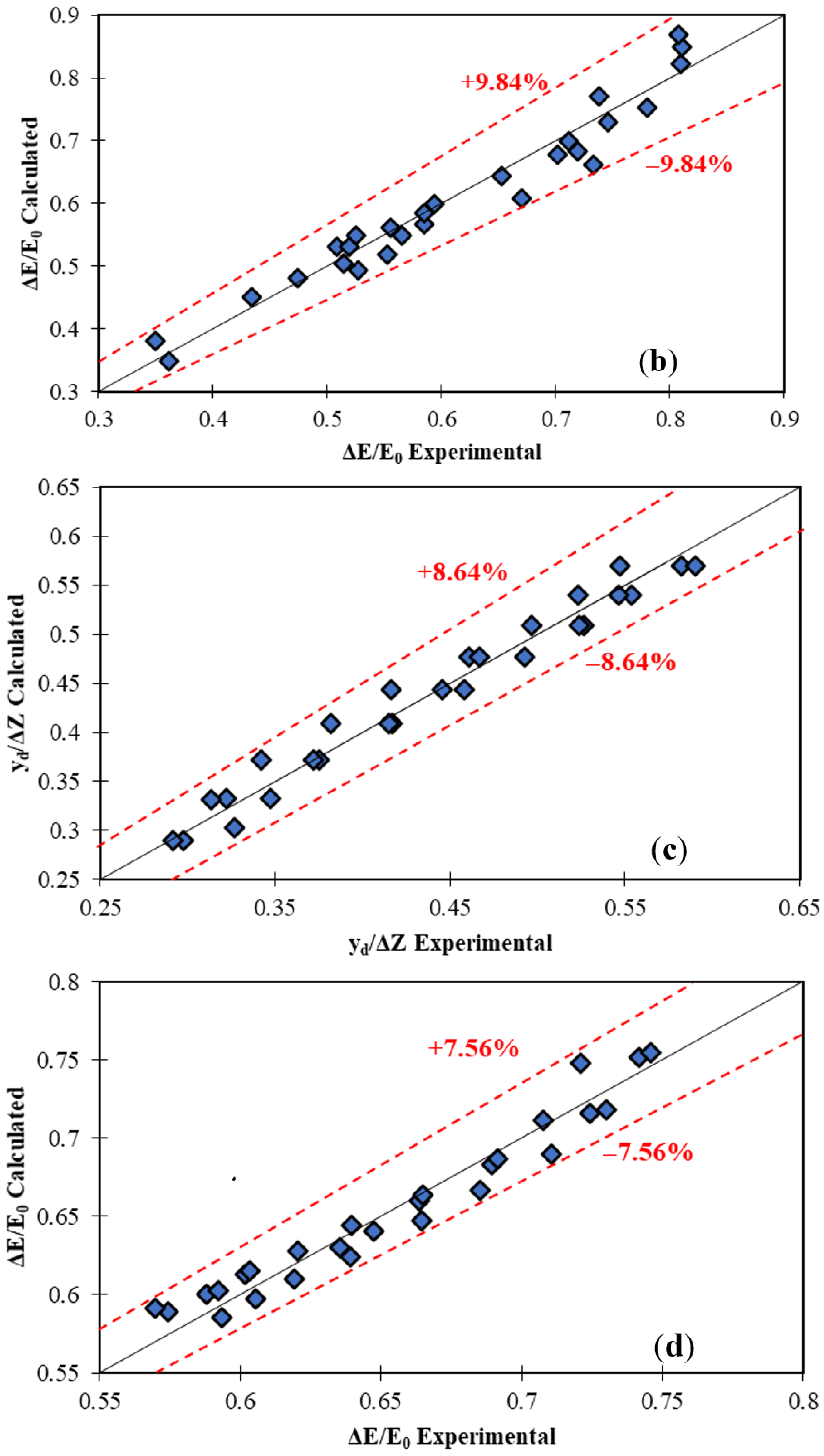
| Dependent Parameters | Number of Equations | Constant Parameters | Criteria Evaluations | Maximum Relative Error | ||||||
|---|---|---|---|---|---|---|---|---|---|---|
| Equation (13) | Equation (14) | a | b | c | d | RMSE | R2 | KGE | ||
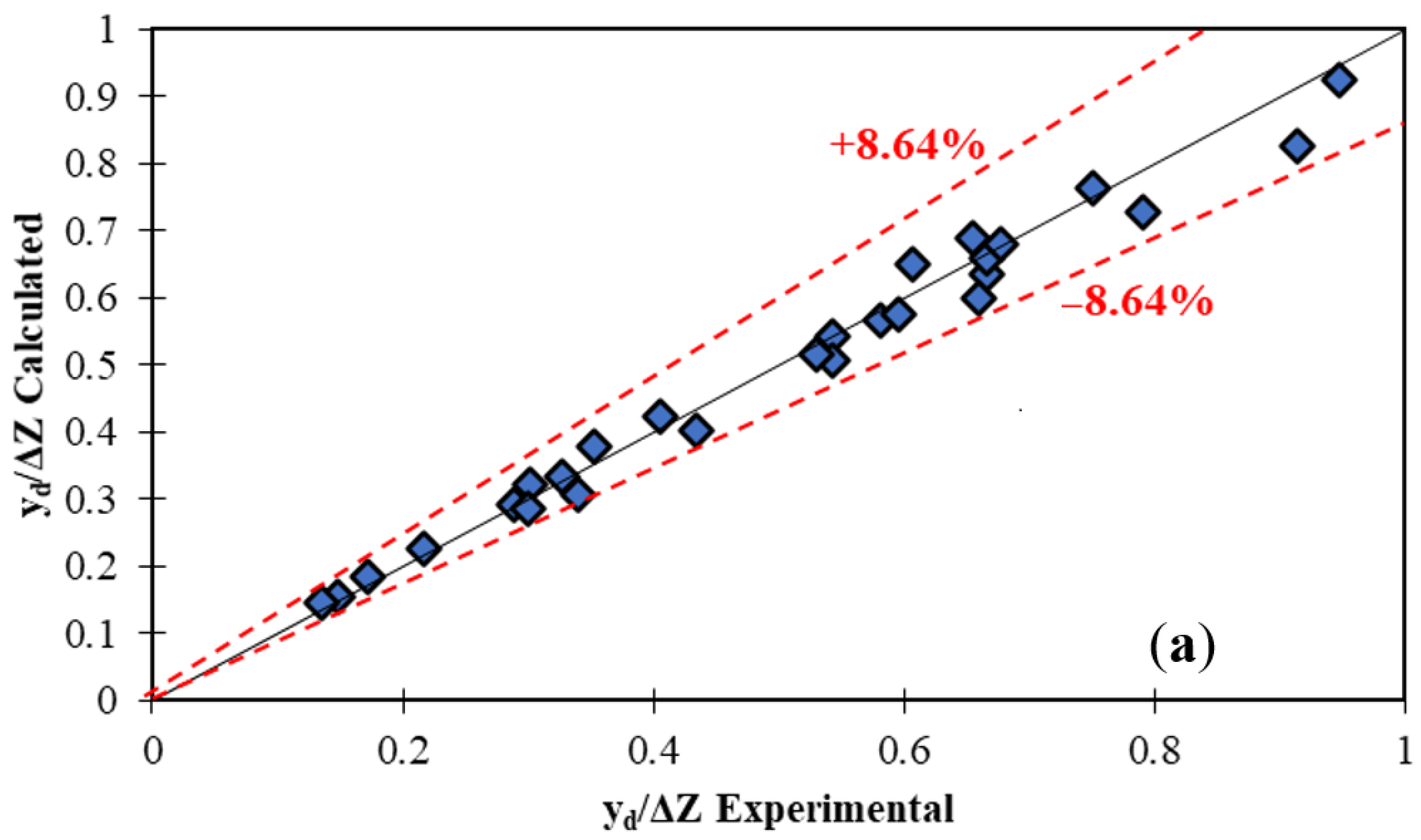
| √ | 7.5706 | 1.9685 | 0.2785 | --- | 0.096 | 0.984 | 0.988 | ±8.64 | ||
| √ | 0.1898 | −0.8055 | −0.0801 | --- | 0.047 | 0.945 | 0.961 | ±9.84 | ||
| √ | 1.6259 | 0.9262 | 0.000706 | 1.0 | 0.0168 | 0.969 | 0.977 | ±8.64 | ||
| √ | 0.4037 | −0.3339 | −0.0135 | 1.0 | 0.0122 | 0.947 | 0.985 | ±7.56 | ||
Publisher’s Note: MDPI stays neutral with regard to jurisdictional claims in published maps and institutional affiliations. |
© 2021 by the authors. Licensee MDPI, Basel, Switzerland. This article is an open access article distributed under the terms and conditions of the Creative Commons Attribution (CC BY) license (https://creativecommons.org/licenses/by/4.0/).
Share and Cite
Daneshfaraz, R.; Aminvash, E.; Bagherzadeh, M.; Ghaderi, A.; Kuriqi, A.; Najibi, A.; Ricardo, A.M. Laboratory Investigation of Hydraulic Parameters on Inclined Drop Equipped with Fishway Elements. Symmetry 2021, 13, 1643. https://0-doi-org.brum.beds.ac.uk/10.3390/sym13091643
Daneshfaraz R, Aminvash E, Bagherzadeh M, Ghaderi A, Kuriqi A, Najibi A, Ricardo AM. Laboratory Investigation of Hydraulic Parameters on Inclined Drop Equipped with Fishway Elements. Symmetry. 2021; 13(9):1643. https://0-doi-org.brum.beds.ac.uk/10.3390/sym13091643
Chicago/Turabian StyleDaneshfaraz, Rasoul, Ehsan Aminvash, Mohammad Bagherzadeh, Amir Ghaderi, Alban Kuriqi, Amir Najibi, and Ana M. Ricardo. 2021. "Laboratory Investigation of Hydraulic Parameters on Inclined Drop Equipped with Fishway Elements" Symmetry 13, no. 9: 1643. https://0-doi-org.brum.beds.ac.uk/10.3390/sym13091643