
Study of Tank Containers for Foodstuffs


1
Degree Course in Transport, University “G. Fortunato”, Viale Raffaele Delcogliano, 12, 82100 Benevento, Italy
2
Department of Agricultural Science, University of Naples “Federico II”, Via Università 100, 80045 Naples, Italy
3
Department of Industrial Engineering, University of Salerno, Via Giovanni Paolo II, 132, 84084 Fisciano, Italy
*
Author to whom correspondence should be addressed.
Machines 2021, 9(2), 44; https://0-doi-org.brum.beds.ac.uk/10.3390/machines9020044
Submission received: 3 January 2021
/
Revised: 17 February 2021
/
Accepted: 18 February 2021
/
Published: 21 February 2021
(This article belongs to the Section Machines Testing and Maintenance)
Abstract
:In this study, we examined a tank container for foodstuff that is generally used for the transport of foodstuffs. With the aid of the “ANSYS R17.0” program code, a numerical model of the tank container for foodstuffs was realized. Further, to validate the considered model, the tank container considered was submitted to the most important ISO tests concerning both its support frame and the tank. The results obtained from the FEM analysis, in terms of displacement for each test, were compared with those provided by the manufacturer and related to the tank container considered, evaluating the difference between the numerical results with the experimental ones. This allowed us to validate the model examined. Furthermore, the results obtained from each test, in terms of stress, have made it possible to locate the areas with the highest equivalent stress and quantify the maximum value, comparing it with the allowable stress. In this way, a better understanding of the structure was achieved, and it was detected that the most stressed area is that of the connections between the container and the frame. Furthermore, modal analysis was carried out, in which the natural frequencies relating to the most dangerous modes of vibrations were found, that is, with the lowest frequency values. Finally, changes for the considered tank container were examined, and it was found that, by changing parameters, such as the thickness of the plate and skirt, and subsequently acting on the arrangement of the corner supports, the highest value of the stresses generated by the loads related to the ISO tests, it is significantly lowered, resulting in a better distributed stiffening of the structure and a reduction, although minimal, of weight. It is evident that this modeling and validation method, suitably integrated by further calculation modules, can be used in an iterative optimization process.
1. Introduction
In the field of freight transport, both by sea and by land, the use of the container is now a fixed point, thanks to the advantages it involves in terms of costs, efficiency and the capability to support different modes of transport: trains, trucks with trailers and ships [1,2,3]. The use of containers for the transport of food products has become increasingly widespread. It is interesting to underline that the development of tank containers for foodstuff has imposed the realization of new techniques related to their handling, which, with the possibility of interchanging the means of transport by ship/truck/rail, constitutes a real science called “interlogistics” [4,5,6], by virtue of which a revolutionary transport technique was developed, which has led, among other things, to the possibility of directly connecting the production sites of a given asset to the final user of the asset considered (door-to-door). All of this is done without performing intermediate handling of the transported goods, with a significant reduction in delivery times and with significant positive implications on the conservation of all the original characteristics of the transported goods and then of the quality of it [7,8,9]. In the present study, we studied a tank container for foodstuff, formed by a rectangular steel frame, inside which there was a cylindrical tank used for the transport of fluids or granular materials, very often used in the food agro-industry.
The container was designed with particular regard to its frame, analyzed using a FEM model. Subsequently we became interested in the tank container by examining the design of its frame, as the evolution of the project in this field has so far been characterized by a “trial and error” process caused by a lack of traditional methods of analysis. [10,11,12].
The consequence of this way of designing involved the presence of the following:
- (a)
- Excessively robust sections, i.e., oversized;
- (b)
- Lack of attention to stiffness issues.
In the present research, the conditions were created to fill this gap by showing a method capable of providing design indications capable of leading to less generous but more accurate sizing, making the construction efficient and safer against the danger deriving from an inattentive study of its natural frequencies.
The goal was achieved by using the ANSYS program, which made it possible to create a valid FEM model of the tank container.
In conclusion, this research basically involved the following steps:
- State-of-the-art;
- Creation of the FEM model, based on the indications taken from a real tank container.
- Simulation of ISO tests and validation of the FEM model.
- Identification of equivalent high-voltage areas in the chassis.
- Calculation of natural frequencies and interpretation of results.
We then proceeded to stiffen the parts most stressed by carrying out the appropriate reiterations, which led to an improvement of the structure.
Therefore, the conditions were created to fill this gap by showing a method capable of providing design indications capable of leading to less generous but more accurate sizing, but more accurate, making the construction efficient and safer against the danger deriving from an inattentive study of its natural frequencies. It was, thus, possible to identify the most stressed parts and appropriately stiffen them, performing the appropriate reiterations that have led to an improvement of the structure [13,14,15].
In the present work, we tried, as far as possible, to give a schematic and rational organization of both the information collected and the results achieved, in order to provide a linear presentation and facilitate consultation.
2. Tank Container for Foodstuff
The basic elements making up a tank container are as follows:
- -
- Frame: Placed on both ends of the container, it consists of four corner blocks, two corners upright and two end crosspieces.
- -
- Corner blocks: small perforated metal structures, welded on the four lower and upper edges of the tank containers, necessary to allow their gripping, transferring, stacking and anchoring.
- -
- End crosspiece: transverse structural element of the lower (upper) part of the frame, of which it connects the lower (upper) corner blocks.
- -
- Side spars: a longitudinal structural element that connects the lower corner blocks of the two end frames.
- -
- Corner upright: a vertical structural element that connects two corner blocks on both sides of an end frame, one upper and the other lower, and thus forming a corner structure.
- -
- Tank.
The corner blocks are suitable for housing the “twistlocks” (rotating pins), which allow us to handle the tank containers or to fix them together (as happens in stacking); in fact, by rotating their lever, they act as a more stable connection between the tank container and the structure on which they have to be located [16,17].
Tank containers must comply with ISO standards, in order to enjoy the benefits of the existence of modern and global infrastructure, increasingly available to handle ISO containers [18,19]. The ISO tank container is a large container for fluids or powders, and it has considerable flexibility; in fact, its transport can take place by road, rail or ship, with the possibility of combining the three ways, with advantages in terms of costs and transport safety. It consists of a single cylindrical tank, called “tank body”, arranged inside a rectangular steel frame; furthermore, the whole structure is in accordance with ISO standards, in particular ISO 1496/3 [20,21]. The most common dimensions are a length of 6.058 m, a height of 2.591 m and standard width of 2.438 m. Furthermore, the tare generally varies between 3000 and 5000 kg; by tare, we mean the mass of the empty tank container in its normal operating conditions, i.e., including all accessories and associated equipment. Today, tank containers can carry a wide range of very different products, such as liquid food products, such as wine, fruit juices, oil, starch, milk, sugar, etc. The most requested accessories for tank containers are inherent to the thermoregulation of the transported product [22,23,24,25]. Furthermore, we must keep in mind that the tank container market is and will be a niche market compared to the box container market, but not negligible. In fact, we must take into account that a tank container has a purchase price that often exceeds that of a box container by ten times, and many transport companies are investing in tank containers, rather than in new tankers, because they are driven by the advantages due to the great versatility related to its transport by road, ship and train [26]. Addressed in this way, a study was performed, to improve the design of tank containers by mean numerical modeling [27].
3. Materials and Methods
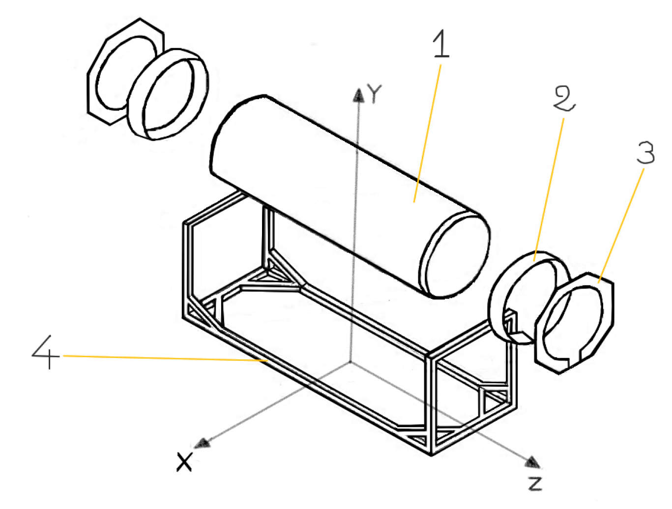
The 3D model of the tank container was realized by mean the “Solid Works” program, and it was subsequently imported, as an IGES file, into the “ANSYS R17” program code to perform the numerical simulations. Only one-eighth of the model was designed and then reflected to generate the entire model, on which we reported the few asymmetries geometric. To model the considered geometry, we used the “beam4” elements for the frame and the “shell63” elements for the tank, the octagonal plate, and the skirt; by doing so, it was possible to “mesh” the whole model by reducing the total number of elements used [28,29,30]. The model, shown in Figure 1, was examined, considering it substantially made up of four basic elements:
- A cylindrical tank,
- Two skirts,
- Two octagonal end plates,
- The frame.
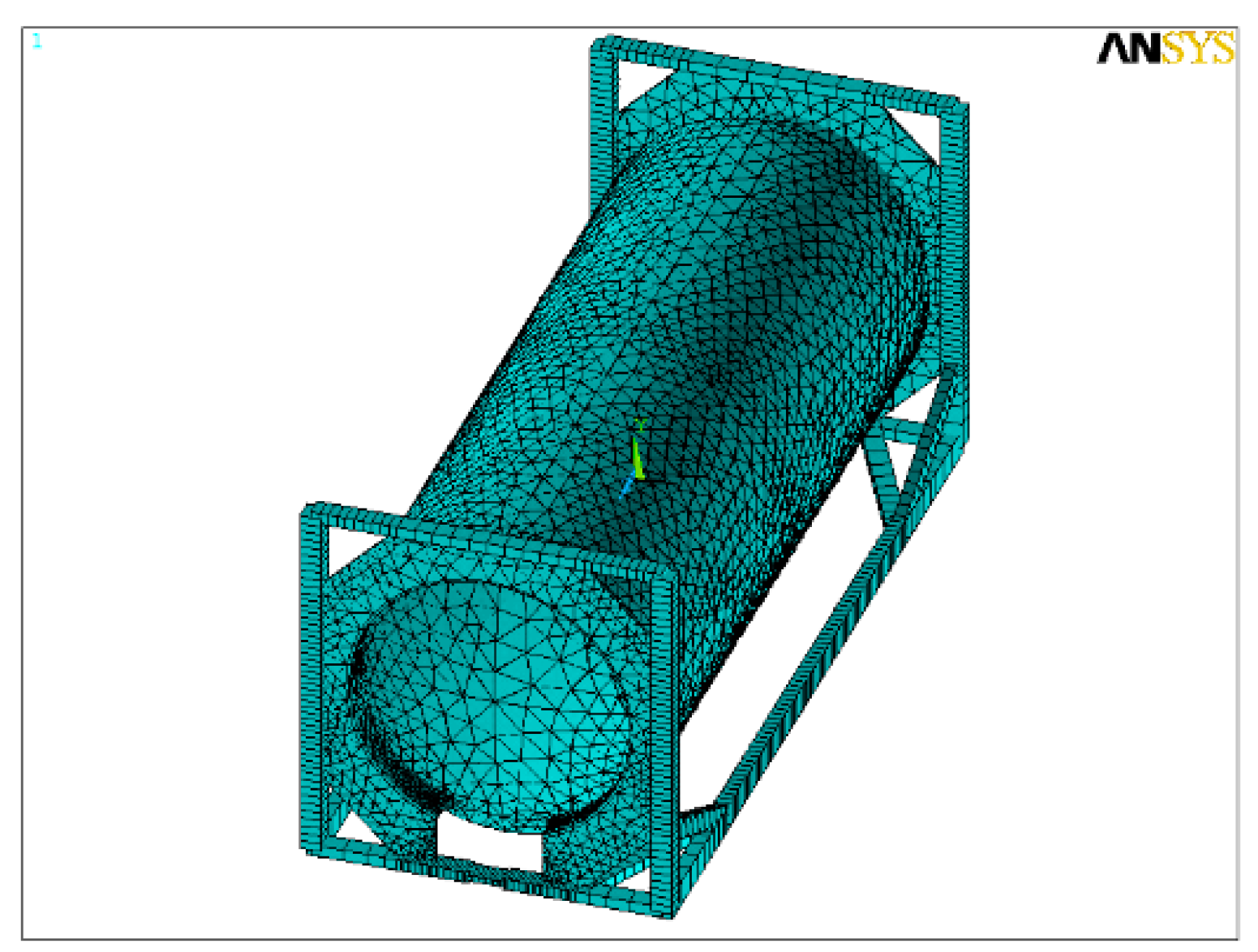
Once the geometric model was realized, the “mesh” was performed. The generation of the mesh was realized according to the “free meshing” method, but it was suitably thickened in the connection area between frame and tank where more precise results are desired (Figure 2).
After to have realized the geometric model, the numerical simulations of the experimental tests ISO for tank container, were performed, defining the constraints and the loads and obtaining the output values of the following:
- -
- Nodal displacements and rotations;
- -
- Normal and bending stresses along y and z;
- -
- Normal stress and flexion deformations along y and z;
- -
- Equivalent stresses according to Von Mises;
- -
- Maximum and minimum normal stresses calculated by default by ANSYS.
4. Experimental Tests ISO for Tank Container
The regulations governing the transport of goods require that before the mass production of a tank container, a manufacturer have to realize a prototype and, to demonstrate its suitability, submitting it to various tests, static and dynamic, in special laboratories, approved and recognized by the competent authorities of different nations. Therefore, the structural tests for the tank containers are as follows:
- -
- Storage test;
- -
- Lifting test using the upper or lower corner blocks;
- -
- Pressure test;
- -
- Test with air;
- -
- Test with water;
- -
- Longitudinal or transverse stiffness test;
- -
- Inspection of all welds.
At pre-set time intervals, we performed the tests, depending on the type of tank and its relative operating time, to ensure its maximum safety. For example, the air test, repeated every two and a half years, makes it possible to check whether the tank is still hermetically sealed. However, the best operators in the industry carry out these tests more often, to increase the safety.
5. Test ISO Description
For the considered tank container, we carried out the following tests, which were performed by the CAIB agency (Companie Auxilliere Industrie Belgique), and the methods of realization are shown in detail in “ISO 1496-3: 1995 (E), section 6.2–6.13” (Table 1) [31,32].
Described below are the tests considered in Table 1:
(1) Stacking test: It has aimed to verify the stacking capacity of a tank container, that is, its ability to support a determined number of them at full load, of the same nominal size and maximum gross mass, in the worst conditions, that for stacking correspond to those of transport by ship. In reality, tank containers almost never have the same weight, so the stacking always takes place in such a way that the lighter one is located in a higher position. However, in order to take into account the accelerations due to the worst wind and sea conditions, a multiplicative coefficient of 1.8 is adopted, in accordance with studies and measurements carried out in this regard in 1980 (BEAU fort 11). Referring, according to the standards, to five tank containers superimposed on a sixth, the total load Q on the latter is 3,178,440 N, obtained by the following formula:
where
Q = 1.8 ∙ R ∙ n ∙ g
- “R” is the maximum gross mass, equal to 36,000 kg,
- “n” is the number of superimposed containers equal to 5 and
- “g” is the acceleration of gravity.
The four uprights, through the corner blocks, must each support a vertical load of about 800,000 N, not exactly centroidal, but with eccentricity (lateral of 25.4 mm and longitudinal of 38 mm) born from the sum of the clearance existing between the containers and with the guide cells on the ship. We placed the tank container, full of water, on a special installation that was blocked by the lower corner blocks; then we performed the test by applying the aforementioned loads on the four uprights. The test carried out according to the indications of ISO 1496/3 resulted in the displacements along X, Y and Z, in mm, of the four vertical uprights, measured at the highest point of contact between the uprights and the octagonal plates and reported in Table 2.
Lifting test: It has aimed to check the tank container’s ability to strengthen to the stresses due to the forces of inertia resulting from the acceleration of the payload upon its vertical lifting, under full load conditions. Realized through its upper or lower ISO corner blocks, carried out by a crane equipped with locks such as to avoid, during the lifting operation, the twisting of the container, the base of which, however, is free to bend. The tank is water filled, and an additional load of 400,000 N is applied to it, with the use of four belts connected to hydraulic pistons. Finally, the tank container, is suspended for a period of 5 min, under these load conditions. Deformations measurements of the tank and frame in the lifting direction are usually made.
(2) Lifting from the upper corner blocks: the measurements are taken for this test both in the midpoint of the lower part of the tank and in the midpoint of the two longitudinal spars. In Table 3, the results are shown.
(3) Lifting from the lower corner blocks: The measurements for this test are taken both at the midpoint of the lower part of the tank and at the midpoint of the two longitudinal spars. In Table 4, the results are shown.
(4) Transverse stiffness test: It has aimed to verify the tank container’s ability to strengthen the stresses due to transverse forces caused by the ship’s rolling motion. According to the standards, the frame is constrained by the four lower corner blocks and it is applied a force of 150,000 N transversely to each upper corner block. The average value found at the end of the test is 3 mm, measured at the highest point of contact between the uprights and the octagonal plates.
(5) Longitudinal stiffness test: It has aimed to verify the tank container’s ability to strengthen the stresses due to longitudinal forces due to the ship’s 15° pitch and a period of 8 s. According to the standards, it is applied a force of 75,000 N longitudinally to each upper corner block of the frame, binding the base through the corner blocks. The average value found at the end of the test is 15 mm, measured at the highest point of contact between the uprights and the octagonal plates.
(6) Restraint test: It has aimed to exam the “locking aptitude”. The test is performed to evaluate the ability of a fully loaded tank container, during transport on rails, to strength to the forces of inertia due to a deceleration of 2 g, when only the base of its frame, is locked by the corner blocks and the lower crosspieces. The tank is water filled, and the maximum gross mass R is 36,000 kg; therefore, the force involved is equal to 2∙g∙R, that is, 706,000 N applied uniformly on the contact areas between the tank and the frame by special equipment. The deformation value found at the end of the test is 4 mm, measured at the highest point of contact between the uprights and the octagonal plates. The overall dimensions of the ISO tank container considered, on which the CAIB has performed the tests, are 2438 m × 2591 m × 6058 m. The frame beams have a box-like section, except in a small section (about 30 cm) of the lower end crosspiece next to the loading and unloading valve, in which the section is solid with dimensions of 150 × 40 mm2. In particular, only in the uprights, the sections are square, while in the other beams, they are rectangular; in Table 5, we summarize the geometric characteristics of the sections.
The material used for the beams is “EN10210/S355 J2H”, steel equivalent to “FE510D” steel, and it has the following mechanical characteristics:
- -
- E = 20,600 daN/mm2 Young module
- -
- σs = 35.5 daN/mm2 Yield stress
- -
- σr = 52.0 daN/mm2 Breakdown stress
- -
- G = 78,400 daN/mm2 Tangential modulus of elasticity
The tank is the maximum gross mass, equal to 36, of 8 mm on the shell and 10 mm on the bottom, and with 316 L steel is formed, having the following mechanical characteristics:
- -
- E = 19,300 daN/mm2 Young module
- -
- σs = 24.0 daN/mm2 Yield stress
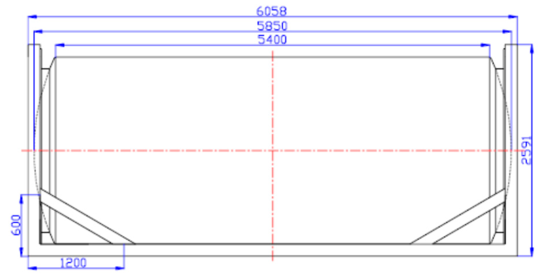
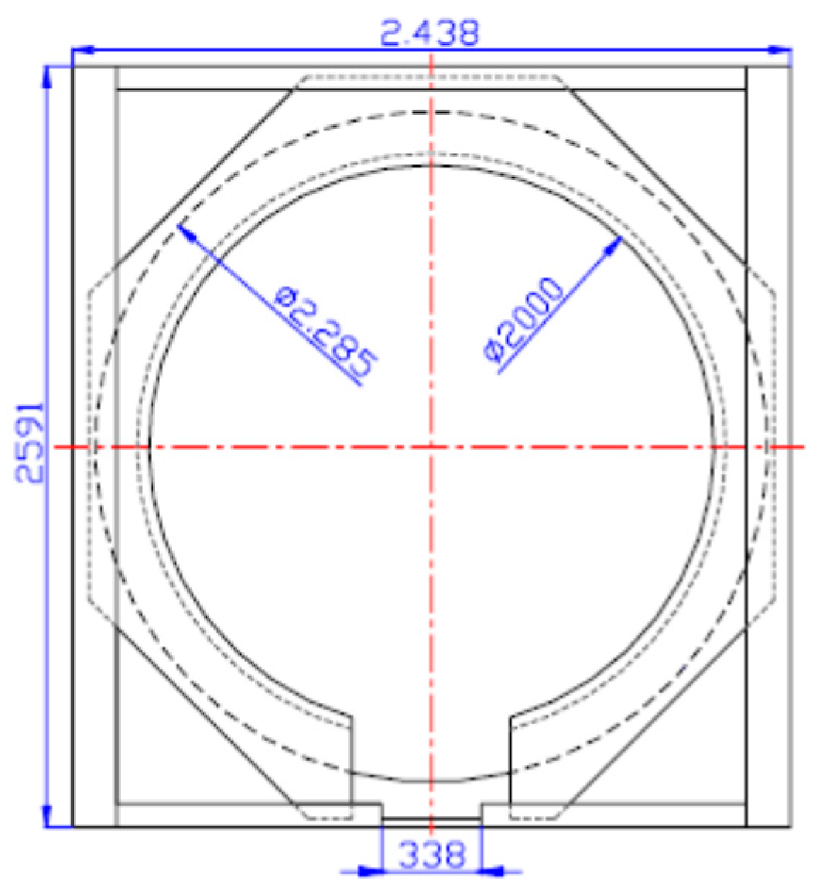
The two octagonal end plates have a central hole with a diameter of 2 m and a thickness of 20 mm. At the end frame and to the skirt are welded, which in turn has an internal diameter of just over 2 m (that is, with the space required to perform the welding with the plate) and a thickness of 45 mm; both are made of “EN10210/S355” steel. The tare weight of the tank container is about 4600 kg, and the dimensions of the different elements that form the tank container are reported in Figure 3, Figure 4 and Figure 5.
Realized the FEM model of the tank container and knowing the mode of application of the loads according to “ISO 1496-3: 1995 (E), section 6.2–6.13”, each of the tests described above was simulated, and the results were compared with the real values available, kindly provided by CAIB. Further, we used a safety coefficient of 1.5 for the stresses. It gave us the allowable stress of the two steels used, for the values indicated in Table 6.
For the determination of the displacements and the stress state, for the considered model, the following assumptions were made:
- Purely elastic deformations and absence of breaks;
- Perfectly isotropic and homogeneous materials;
- Length of the elements, such as to ensure that the edge effects are negligible;
- No thermal expansion.
On the meshed model, first interlocking constraints on the base of the frame were applied, and then subsequently the loads on the four uprights, making sure to also consider the eccentricity. This was done with the aid of four small appendices, connected to the ends of the uprights and suitably arranged, on which the decentered load of the required value was applied. Furthermore, a verification on the combined bending and compressive stress was performed, and for that, the critical load for the uprights was determined to be equal to 0.427∙109 N. Considering the load due to stacking, we performed a numerical simulation, and the following results were obtained:
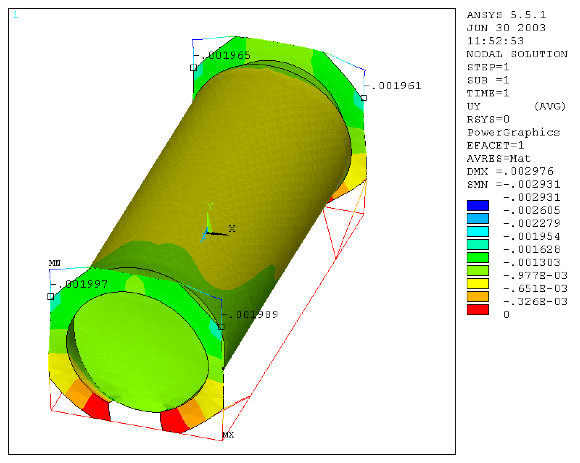
1. Displacements along Y-axis
An average value of displacement along Y equal to about 2 mm was calculated (Figure 6). This value, compared with that of 2.15 mm, provided by the manufacturer, gives us a percentage error of about 7%.
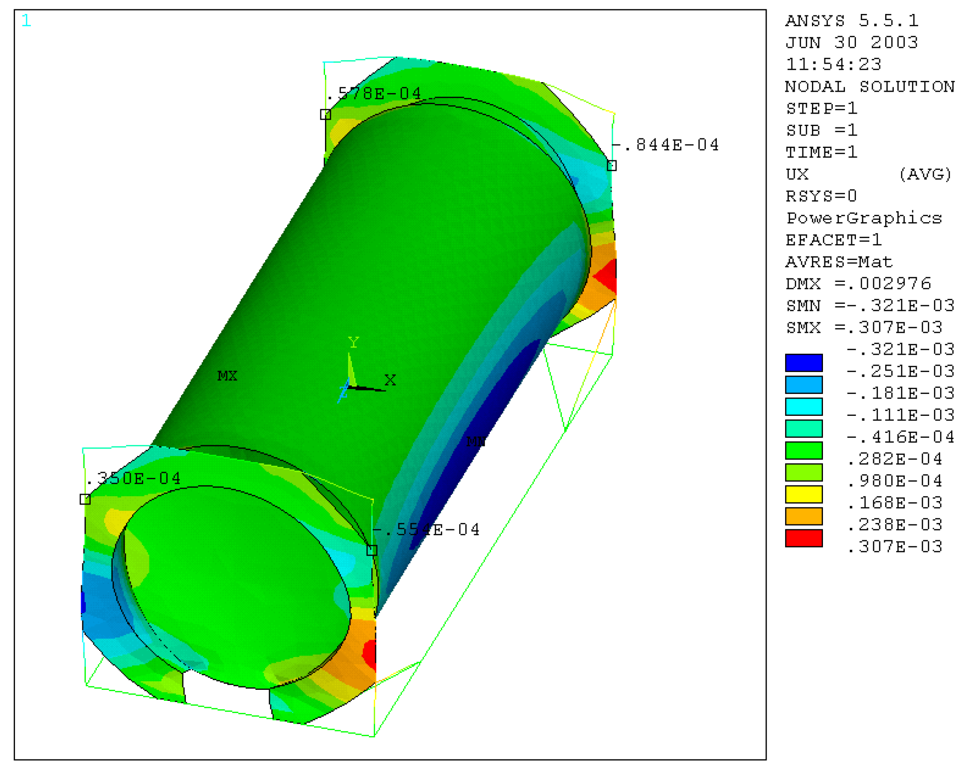
2. Displacements along X-axis
An average value of displacement along X equal to 0.58 mm was calculated (Figure 7), which compared with that of 0.66 mm, provided by the manufacturer, gives us a percentage error of about 12%.
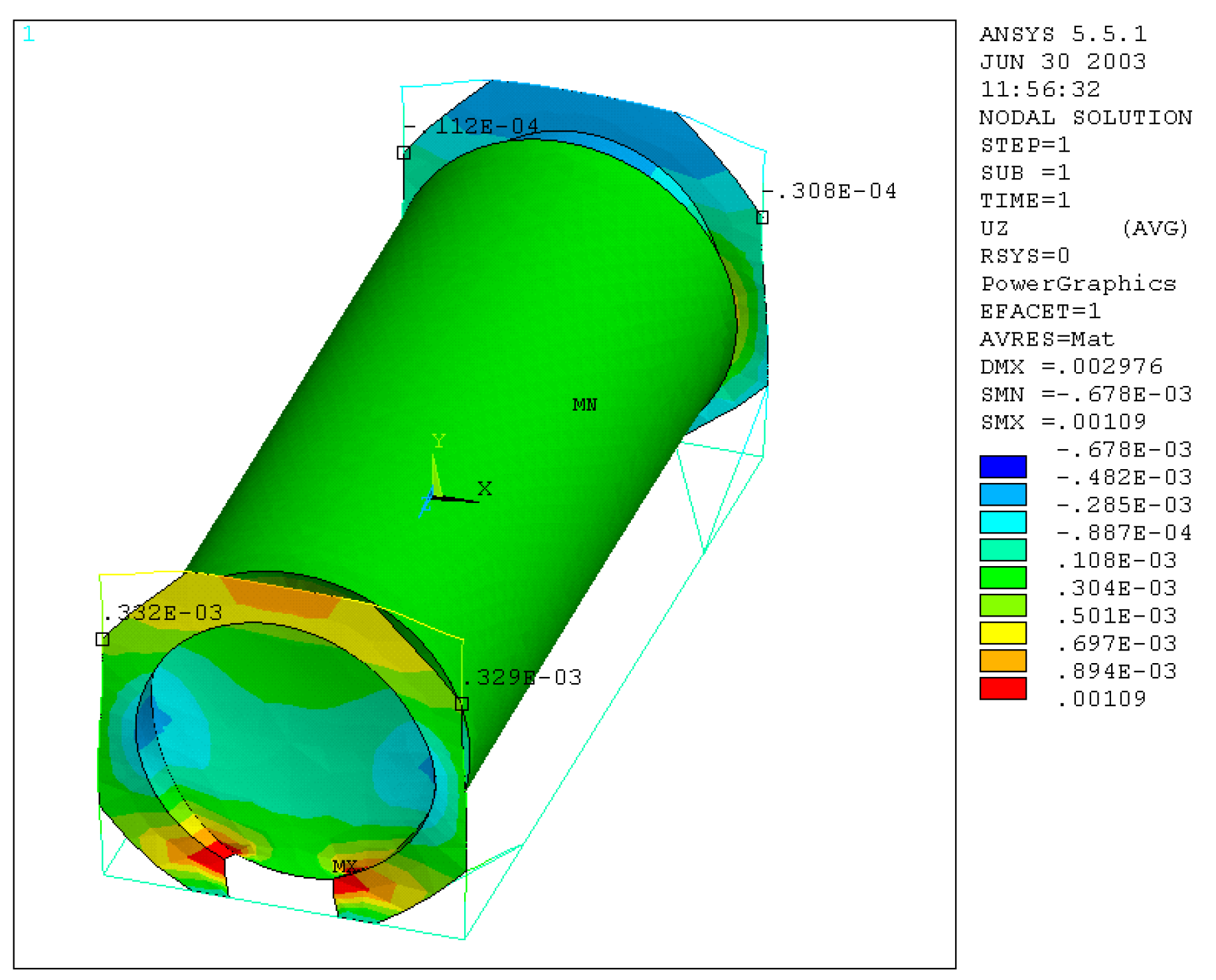
3. Displacements along Z-axis
An average value of displacement along Z equal to 0.18 mm was calculated (Figure 8), which, compared with the value of 0.42 mm, provided by the manufacturer, gives a percentage error of about 57%, which is much higher than the previous ones and could be attributed to a lack of the adopted FEM model. In general, it is interesting to observe how there are different values in the two end frames; in fact, they differ by an order of magnitude, and this is due to the presence of the discontinuity in one of the two plates, due to the need for space for the use of the loading and unloading valve.
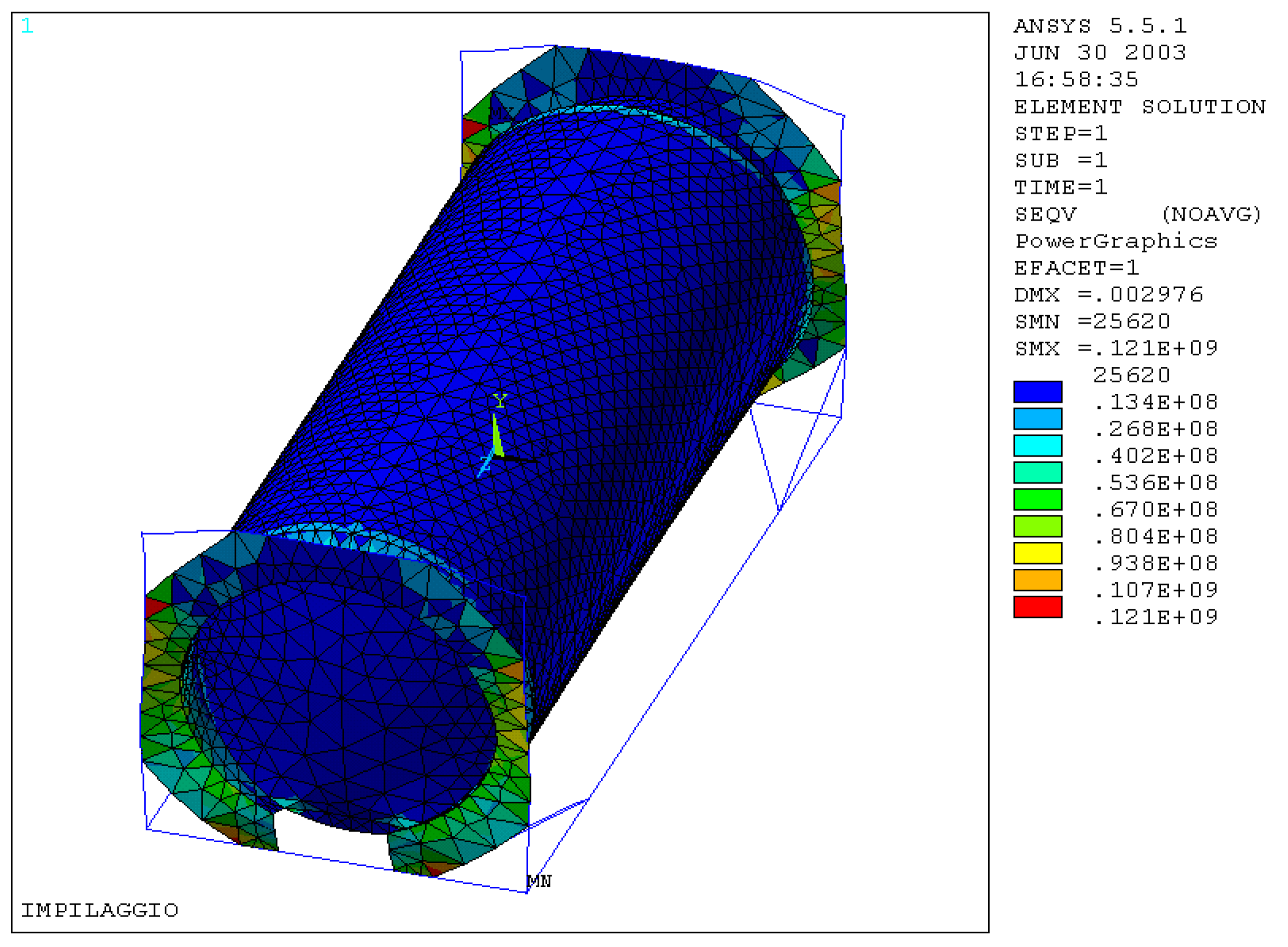
Verification of the stresses generated on the whole structure was performed, the results of which are highlighted in Figure 9, and it was seen that the maximum equivalent stress, for both materials used, does not exceed the admissible one, so that the structure is able to strength to the load applied within the safety margins imposed. Furthermore, we detected the maximum value of the equivalent stress in the contact area between the upright and the octagonal end plate.
6. Lifting by Upper-Corner Blocks
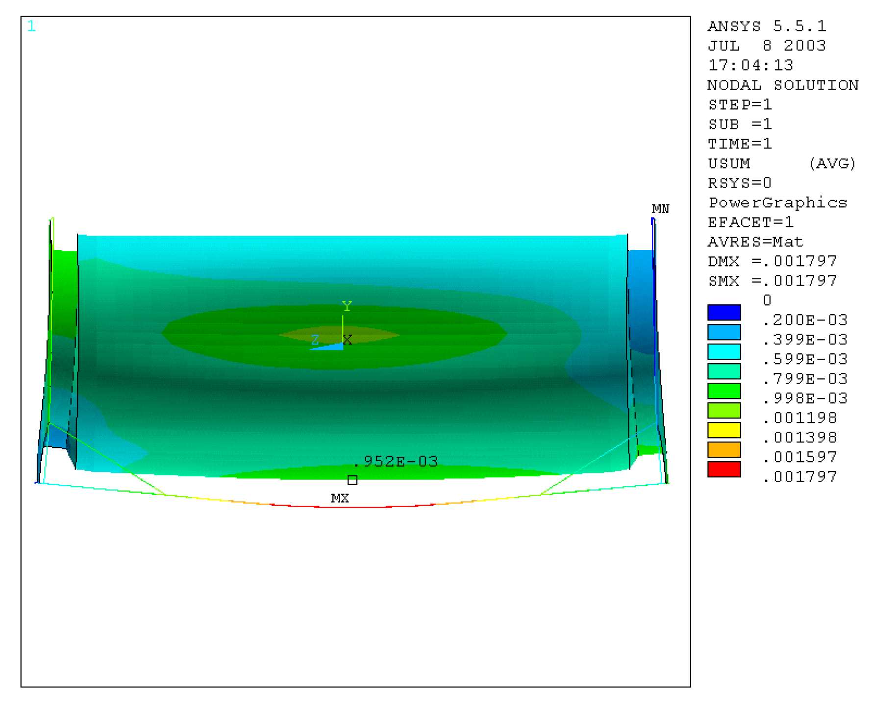
The tank container was constrained by its four upper-corner blocks, making the structure isostatic, but also allowing it to deform, under the applied load, just as would happen in the case of a lift of this type. As regards the loads, we simulated the presence of water by considering the pressure that this applies on the lower half of the tank, and then using a macro created by us in ANSYS code, the pressure on each element was calculated, putting it in relation to the position it occupies inside the tank. To make this, it was necessary to change the type of mesh on the shell, using shell elements 63, with a more regular shape, to have better distribute the pressure inside it. The additional load of 400,000 N applied by belts on the shell of the tank was considered by increasing the weight and by acting on the density; finally, an acceleration of 2 g upwards was applied to the whole structure. It can be seen, by examining the displacements and the deformation, how the tank deforms, to expand in its underlying part and to contract in the lateral one. The displacement of the spars in their midpoint is equal to 1.8 mm (Figure 10), which coincides with the real value; but on the other hand, there is a lowering of the tank at its midpoint equal to about 1 mm, which gives an error of 50% in default compared to the real one.
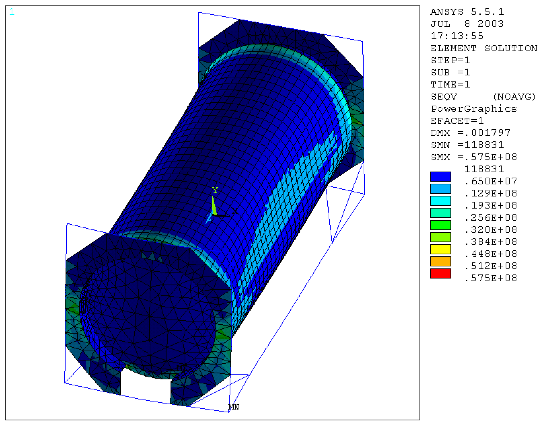
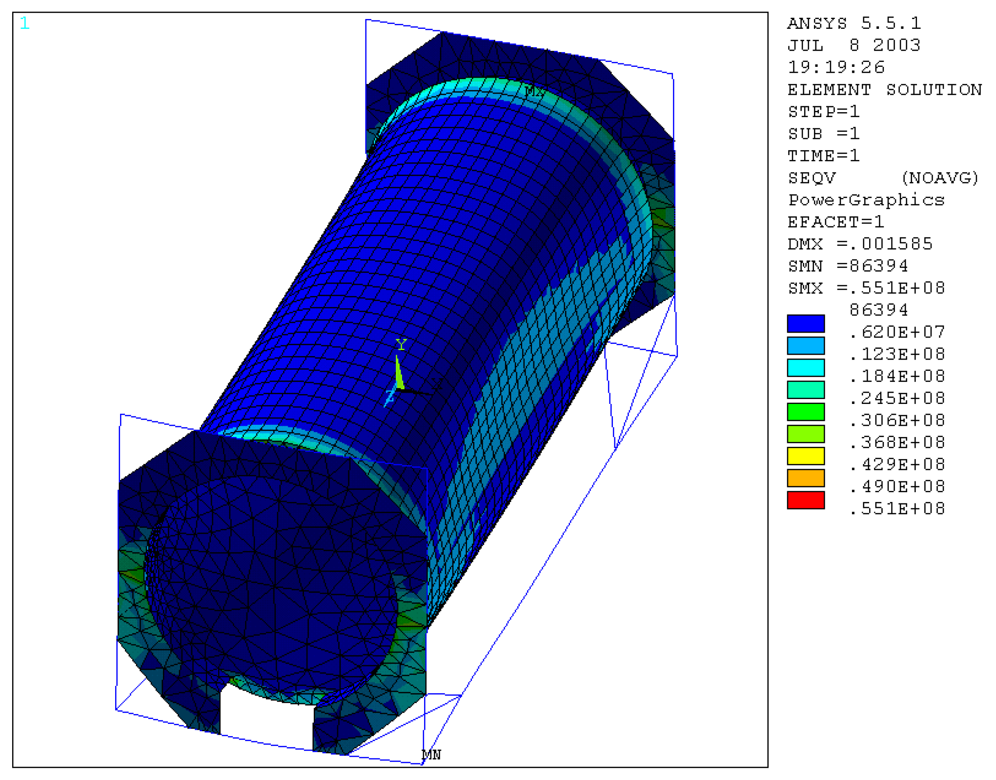
The equivalent stresses calculated according to Von Mises are below the allowable ones (Figure 11), and the maximum value detected is 0.575 ∙ 108 N/m2 near the connection of the tank with the skirts. As regards the frame beams, the normal and bending stress tension, which, in ANSYS, are indicated as “Nmis1”, have detected that the most stressed area is that part of the lower crosspiece in which the section is reduced, due to the presence of the loading and unloading valve.
7. Lifting through Lower Corner Blocks
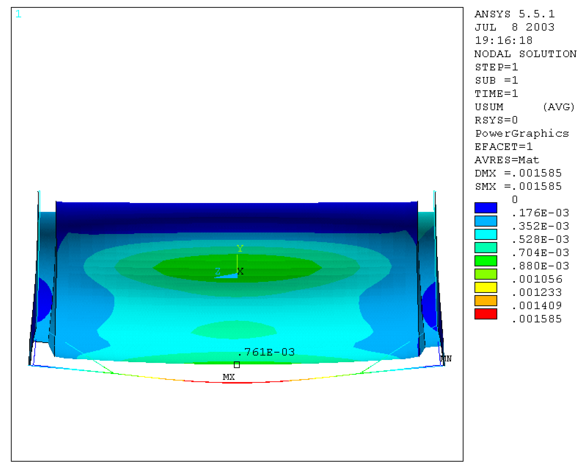
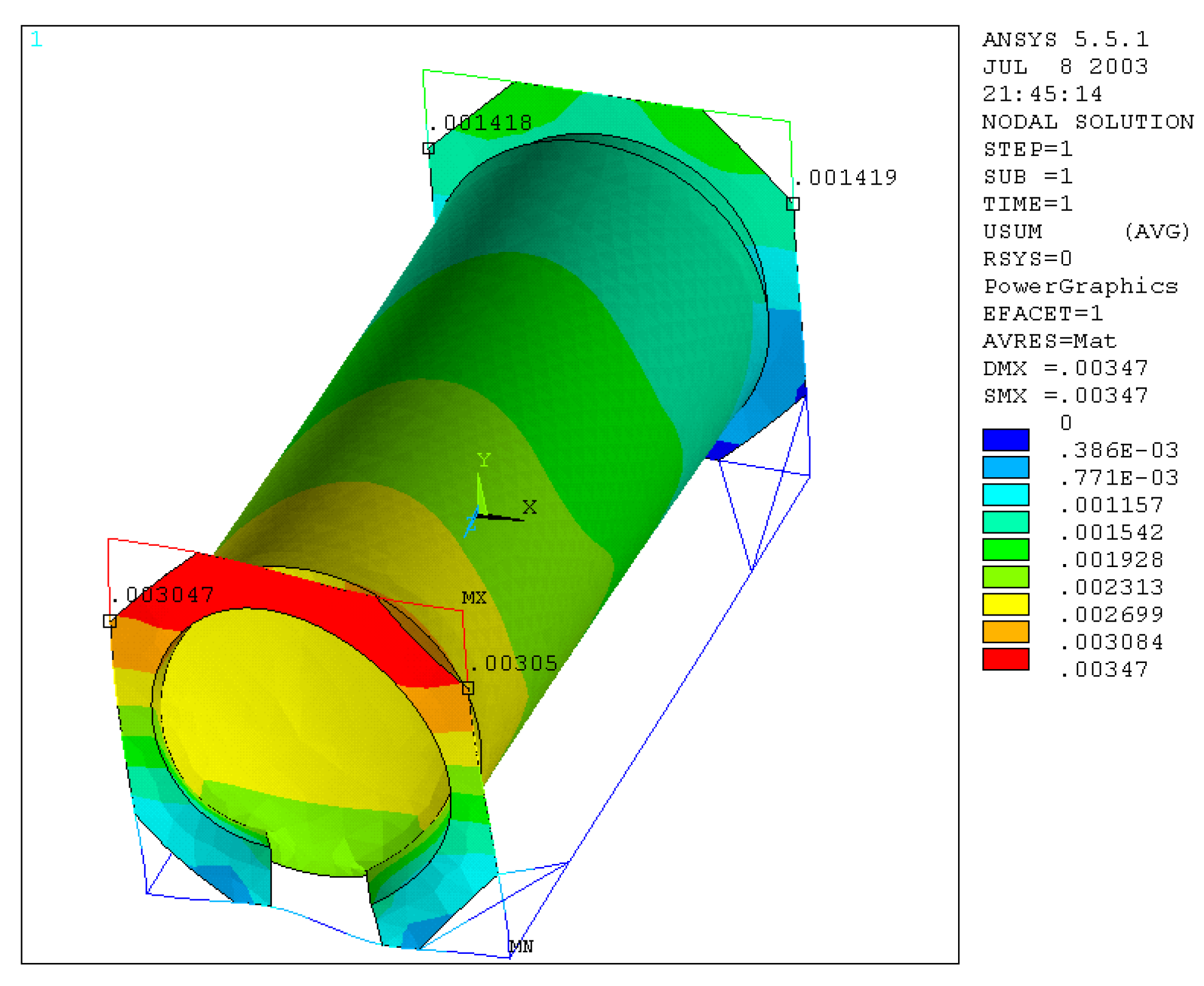
The load application method is the same as in the previous case, but the lifting grip changes, so the constraints have to be located to the lower corner blocks. The deformed has the same shape as that due to the lifting for the upper corner blocks, but with lower values. The displacement of the spars in their midpoint is equal to 1.6 mm (Figure 12), which with respect to the real value of 1.5 mm, gives an error of 6.5%. Then, the lowering of the tank was determined in its midpoint equal to 0.8 mm, which gives, as in the previous case, an error of 50% below the real one of 1.6 mm. The equivalent stresses calculated according to Von Mises are below the allowable ones (Figure 13), and the maximum value detected is 0.551 ∙108 N/m2, near the connection of the tank with the skirts.
The normal stress and bending stress of the frame beams indicate that the most stressed area is, once again, that part of the lower crossbar, where the section is reduced.
8. Transverse Stiffness
Constrained the tank container by the lower corner blocks, a load of 150,000 N was applied to each of the four upper corner blocks in the cross direction. The deformation shows how the model deforms differently in the two frames, the deformation is greater where there is the discontinuity of the octagonal plate. The nodal displacements identified in the highest point of contact between the frame and the upright, have an average value of 2.4 mm, which, compared with the real one of 3 mm, gives an error of 20% (Figure 14).
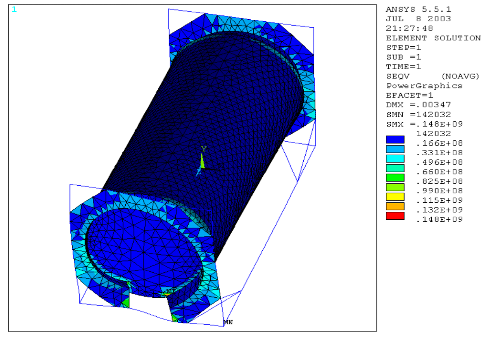
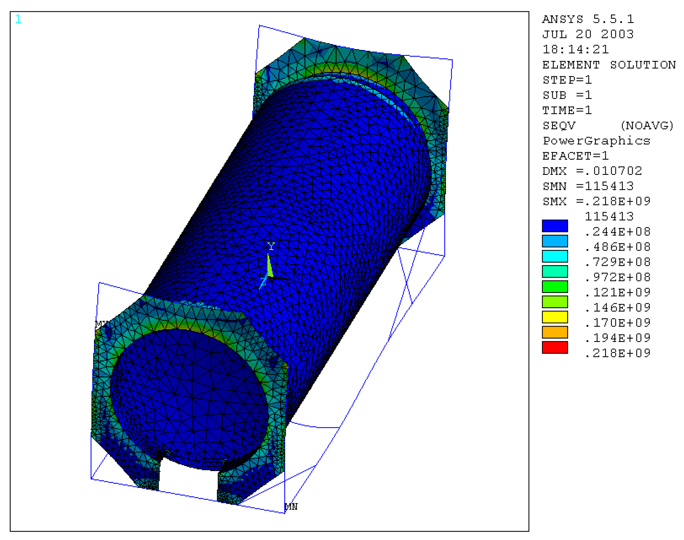
It was noted, considering the equivalent stresses according to Von Mises (Figure 15), that the maximum reached is equal to 0.148 ∙ 109 N/m2 in the area between skirt and tank, which does not exceed the allowable stress. In addition, we detected high stress values in the contact areas between the plate and the lower-end crosspiece.
The normal stress and bending stress of the frame beams take values below the allowable one, and the most stressed point is the one next to the lower right corner block of the end frame.
Longitudinal Stiffness
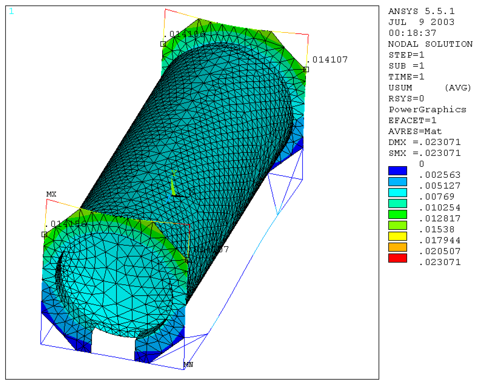
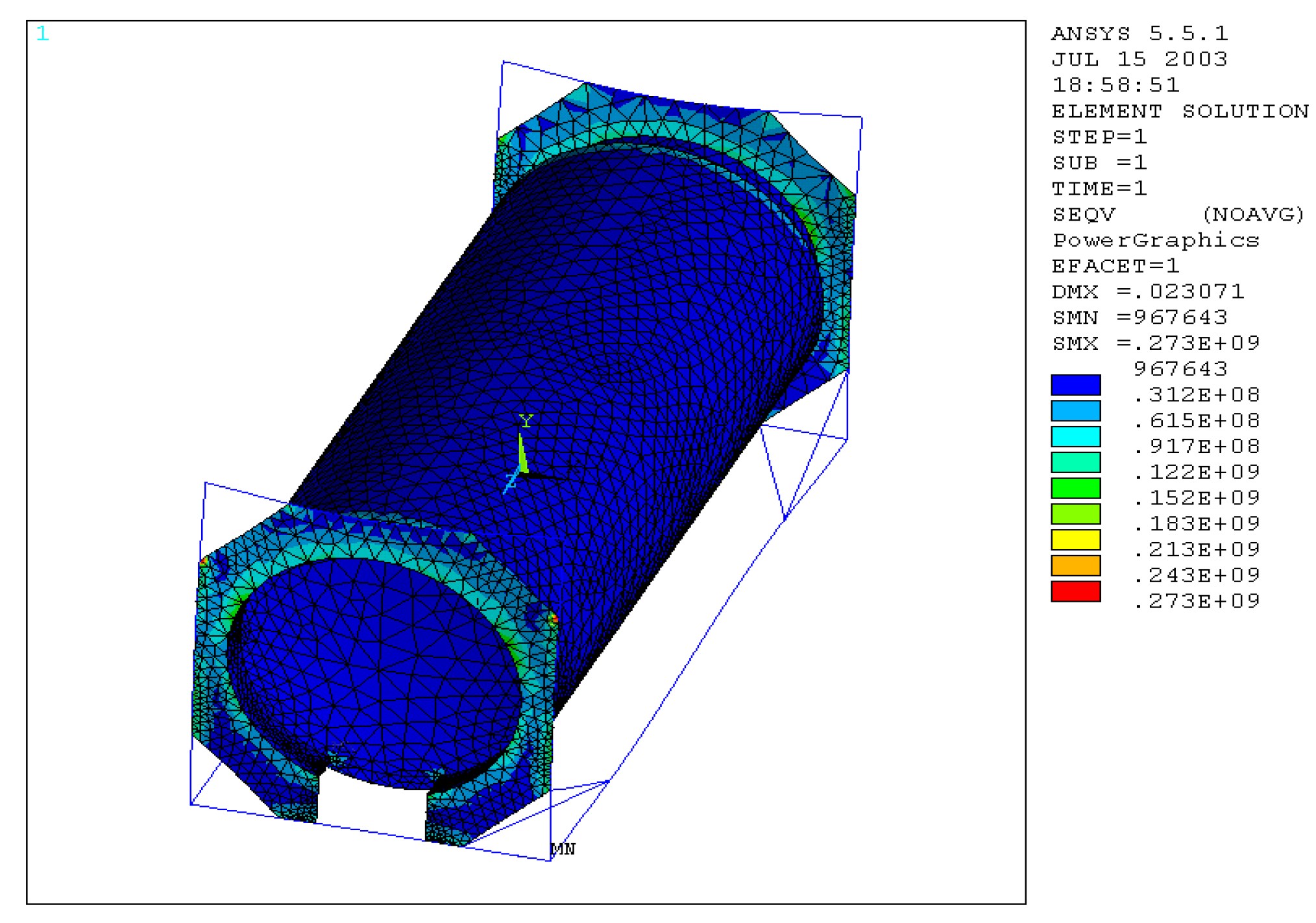
We constrained the tank container by the lower corner blocks and applied the load of 75,000 N to each of the four upper-corner blocks in the longitudinal direction. Then, we examined the nodal displacements identified in the highest point of contact between the frame and the upright. They have an average value of 14 mm, which compared to the real one of 15 mm gives an error of 6.6% (Figure 16). The equivalent stress according to Von Mises (Figure 17) assumes a maximum value at the highest point of the plate-upright attachment, equal to 0.273 ∙ 109 N/m2, which, albeit slightly, exceeds the allowable stress.
The normal stress and bending stress of the frame beams assumes a maximum value equal to that allowable in the central area of the two upper end crosspieces; this is certainly because the octagonal plates welded to them in that area make them very stiff.
9. Carriage Anchoring Simulation
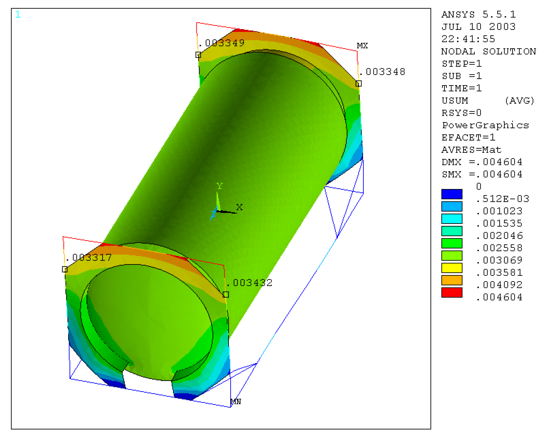
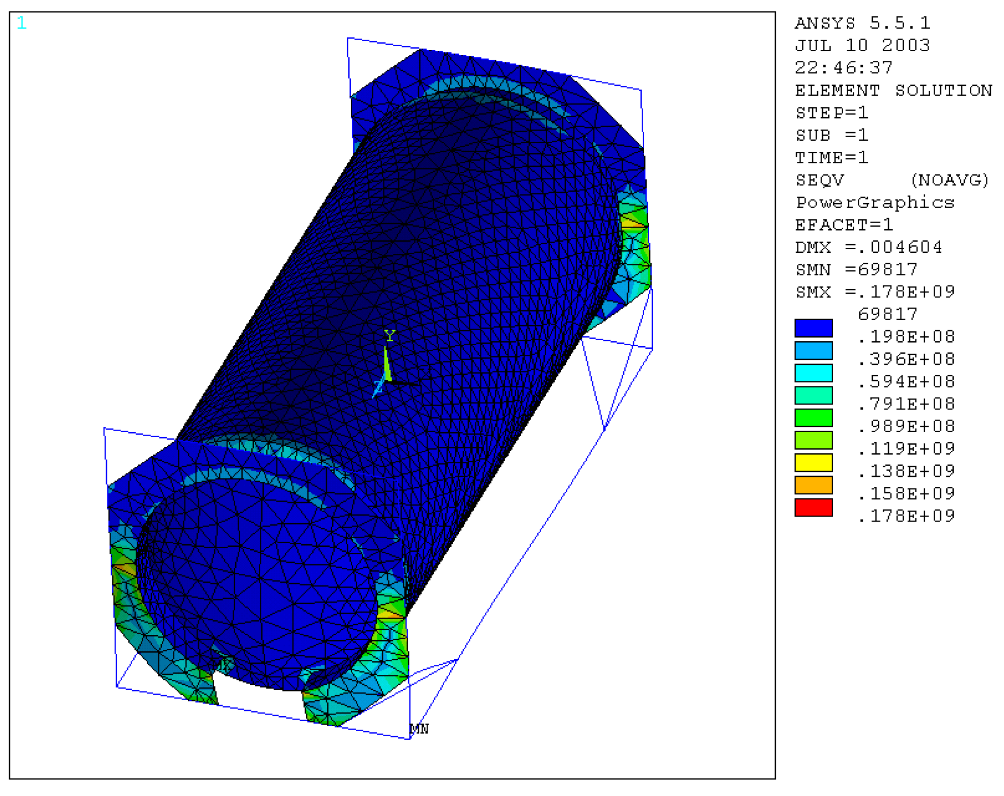
The base of the frame of the model was constrained in such a way as to reproduce the anchorage to a carriage of a freight train. Then, we inserted a volumetric element inside the surfaces making up the tank, which, suitably generated and then meshed with solid45 elements. Defining R as the maximum gross mass equal to 36,000 kg and T as the tare of the tank container, the inserted volume is that of the mass (R–T), which, together with the tare of the tank container, has to be submitted to a deceleration equal to 2 g, to verify the stresses due to the consequent inertia forces that arise. The results show that the average of the nodal displacements (Figure 18) in the indicated points is equal to 3.4 mm, which, compared with the real value of 4 mm, gives an error of 15%. The equivalent stresses, according to Von Mises (Figure 19), are below those allowable for both materials used, the maximum value found is in correspondence with the plate–skirt connection, in the valve area, but equally high values occur in the lateral area of the octagonal plate.
On the corner supports, as regards the normal stress and bending stress of the frame beams, we noted the greatest value.
10. Dynamic Analysis of Tank Containers for Foodstuff
The dynamic analysis [33,34] of the considered structure was performed, and two cases were examined:
- Empty tank;
- Tank full of water.
In the first case, we evaluated the deformations and the natural frequencies relative to the first 10 modes of vibrations. For this analysis, it was necessary to furnish two other quantities that characterize the material, such as the density and Poisson’s ratio.
These values are for steel: density ρ = 7850 kg/m3; Poisson’s ratio υ = 0.3.
The tank container was constrained as in the case of road transport with trucks, with a hinge in each of the two lower corner blocks of the frame, while in the remaining two lower ones of the other frame with two carriages arranged to prevent longitudinal and vertical displacement. We collected the values of the natural frequencies of vibrations, in Hertz, and they are presented in Table 7.
In the second dynamic analysis, we examined the water-filled tank, and the data results are reported in Table 8
11. Discussion
By mean the analysis of the obtained data results, it was possible to note that the FEM model created is substantially faithful to reality, especially as far as it concerns the frame.
Data results comparison
In Table 9, the values obtained by experimental tests (Real Value) and numerical simulations (FEM Value) are reported.
It is possible to note that, for the stacking test, the percentage maximum error is 57% for Uz, while for Ux and Uy, the percentages are 12% and 7%, respectively.
For the Top Lift test, the spar element presented a negligible error, while for the tank element, the percentage maximum error is 50%.
For the Lower Lift test, the spar element presented a percentage error of 6%, while for the tank element, the percentage maximum error is 50%.
For the Transverse Stiffness test, the upright element presented a percentage error of 20%.
For the longitudinal Stiffness test, the upright element presented a percentage error of 7%.
For the Restraint test, the upright element presented a percentage error of 15%,
Therefore, only for the upright element during the stacking test we detected, for Uz value, a big difference (57%), as well as for the tank element during the top and lower lift test (50%).
For the Dynamic Analysis of Tank Containers, it was possible to note the following:
Case 1: From the analysis of the results, it is immediately evident how mode 1 of vibrating is the one that distances itself from the others in a greater way for the value of the natural frequency, equal to 3.54 Hz; in fact, Mode 2 has a value of 12.67 Hz and the third of 18.99 Hz.
Case 2: From the analysis of the typical deformations relating to the first five modes of vibrations, it is possible to note a decrease in the system natural frequencies, and this is justifiable if we consider that, without prejudice to all the other geometric and material parameters of the tank container, the inertia of the system is greater. It is therefore evident that the dynamic response of the tank container changes depending on whether the tank is empty or full.
The results of the first analysis can therefore be taken as a reference in the event that the tank container is transported empty or at the limit, and filled with a fluid with a low specific weight; instead, the last analysis can be useful in the opposite case.
In order to adopt strategies to improve the response of the structure to the forcing actions coming from the roughness of the ground, one should know the estimated value of these frequencies, which are related to the profile of the soil and the speed of travel of the means of transport.
A further forcing cause may be the so-called sloshing of the liquid inside the tank, so much so that there are rules that regulate the filling percentage of a tank container. This percentage must be greater than 80% or less than 20% of the total volume available.
12. Improvements Made to the Tank Container
On the basis of the study carried out, in order to improve the performance of the tank container considered, changes were made for the parts that, from the FEM analysis, were found to be more stressed. In particular, the possibility of modifying the attachment points to the frame of the corner supports was studied, by at first keeping their inclination constant, and then varying it in an appropriate range of values; subsequently, the thicknesses that characterize the components of the frame were changed, particularly on that of the octagonal plate and the skirt. All of this was done to determine a combination of these parameters that allows, at least for the same weight, a better response to the extreme stresses to which the tank container is submitted in the ISO tests, in particular for the longitudinal rigidity, which is the most burdensome for the tank container. For the considered model, the following hypotheses were made for the identification of the displacements and the stress-state:
- Purely elastic deformations and absence of breaks,
- Perfectly isotropic and homogeneous materials,
- Length of the elements, such as to ensure that the edge effects are negligible,
- No thermal expansion.
The tests were performed, maintaining constant the characteristics of the following:
- (a)
- Spar and upright;
- (b)
- End crosspiece;
- (c)
- Tank.
Instead, the following geometric parameters were alternatively changed:
- (1)
- Thickness of the octagonal endplate, in the range (0.015 ÷ 0.020 m),
- (2)
- Thickness of the skirt, included in the interval (0.035 ÷ 0.045 m),
- (3)
- Displacement of the corner supports, with a constant angle,
- (4)
- Angle supports inclination, included in the interval (30° ÷ 45°).
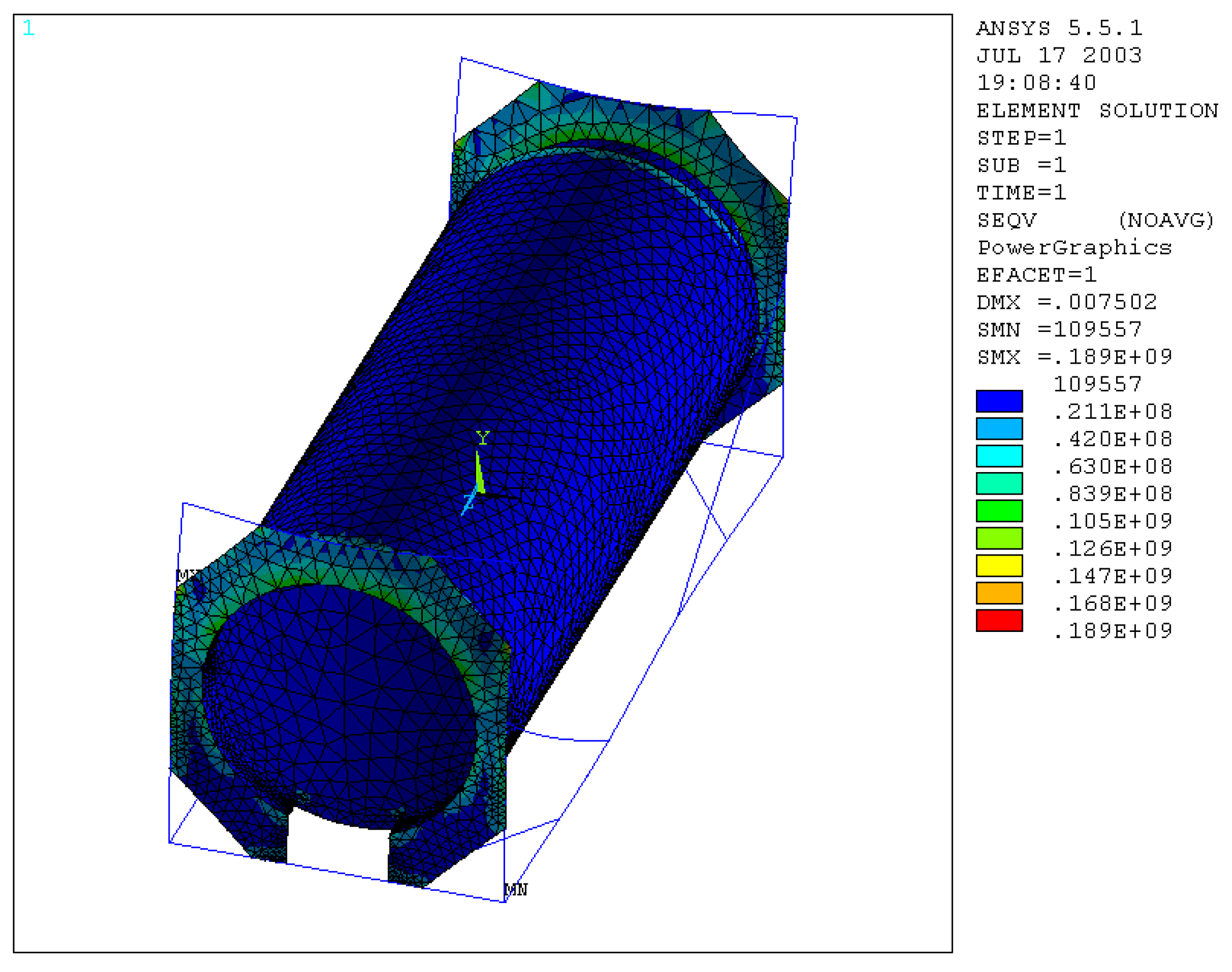
Keeping the angle of 30° constant, starting from the displacement of the corner supports, an increasing reduction of the maximum equivalent stress was found due to the longitudinal stiffness test, which was 0.273 × 10⁹ N/m2, and it reached a value of 0.189 × 10⁹ N/m2 in the contact area between the upright and frame, in which the connection with the upright is at a height of 1.2 m, while with the spar it is equal to 2.4 m (Figure 20).
For the normal stress and bending stress of the beams, the speech is the same, as there is a reduction in the maximum equivalent stress, identified in the upper end crosspiece, which assumes a value of 0.131 × 10⁹ N/m2 against the previous 0.240 × 10⁹ N/m2.
Reducing the thickness of the plate and the skirt by 5 mm, we obtain that the value of the maximum equivalent stress increases up to a value of 0.218 × 10⁹ N/m2 (Figure 21), as well as the normal and bending stress.
By trying to change the inclination from 30° to 45°, while maintaining the same attachment on the upright, we obtained a maximum stress value of 0.243 · 109 N/m2 (Figure 22).
The data results obtained indicated that the 30° position was the best.
In summary, with these changes, we reduced the maximum tension in the longitudinal stiffness test, increasing the transverse one, but in a balanced way, as this too does not exceed the allowable stress. We obtained, in addition, an overall weight reduction of 55 kg, resulting from the algebraic sum of the reduction in the thickness of the plate and skirt and the increase in the length of the supports.
13. Conclusions
This study made it possible to evaluate the behavior of a tank container for foodstuff. By comparing the results obtained from experimental tests and numerical simulations, it was possible both to validate the numerical model considered and to determine the areas with the highest equivalent stress and quantify the maximum value by comparing it with the allowable stress. In this way, we achieved a better understanding of the structure and detected that the most stressed area is that of the connections between the container and the frame [35,36]. The developed FEM model could be used for the following purposes:
- -
- Allowing changes in the design phase of the tank container, in relation to the responses of the model during the ISO tests, in such a way as to facilitate their overcoming, without however exceeding with oversizing.
- -
- Optimizing the model by aiming at a significant reduction in the weight of the chassis, which would entail the possibility of increasing the transport payload without any additional cost.
A more in-depth study should be performed in the future, with the optimization of the frame. The classic solution is the one that uses objective functions.
The limit of this approach, which operates by means of discretization, is a considerable amount of calculations; the greater they are, the greater the discretization is. The sensitivity analysis aims to identify the contributions given by various parameters that characterize the structure in terms of strength and weight, providing design indications capable to obtain less generous, but more accurate sizing, which is better suited to stress problems detected by the tank container examined [37,38,39].
Author Contributions
A.L., A.F., A.P. and F.V. equally contributed to carrying out the research, whose results are reported in this work. All authors have read and agreed to the published version of the manuscript.
Funding
This research received no external funding.
Data Availability Statement
Not applicable.
Conflicts of Interest
The authors declare no conflict of interest.
References
- Bahreini Toussi, I.; Kianoush, R.; Mohammadian, A. Numerical and Experimental Investigation of Rectangular Liquid-Containing Structures under Seismic Excitation. Infrastructures 2021, 6, 1. [Google Scholar] [CrossRef]
- Li, J.-Q.; Myoung, N.-S.; Kwon, J.-T.; Jang, S.-J.; Lee, T. A Study on the Prediction of the Temperature and Mass of Hydrogen Gas inside a Tank during Fast Filling Process. Energies 2020, 13, 6428. [Google Scholar] [CrossRef]
- Batarliene, N. Essential Safety Factors for the Transport of Dangerous Goods by Road: A Case Study of Lithuania. Sustainability 2020, 12, 4954. [Google Scholar] [CrossRef]
- Sasaki, N.; Kuribayashi, S.; Fukazawa, M.; Atlar, M. Towards a Realistic Estimation of the Powering Performance of a Ship with a Gate Rudder System. J. Mar. Sci. Eng. 2020, 8, 43. [Google Scholar] [CrossRef] [Green Version]
- Wilson, J. The Model Railroader’s Guide to Intermodal Equipment & Operations. In Kalmbach Books; Kalmbach Pub Co.: Waukesha, WI, USA, 1999. [Google Scholar]
- Frosina, E.; Senatore, A.; Andreozzi, A.; Fortunato, F.; Giliberti, P. Experimental and Numerical Analyses of the Sloshing in a Fuel Tank. Energies 2018, 11, 682. [Google Scholar] [CrossRef] [Green Version]
- Zhao, J.; Zhu, X.; Wang, L. Study on Scheme of Outbound Railway Container Organization in Rail-Water Intermodal Transportation. Sustainability 2020, 12, 1519. [Google Scholar] [CrossRef] [Green Version]
- Formato, A.; Guida, D.; Ianniello, D.; Villecco, F.; Lenza, T.L.; Pellegrino, A. Design of Delivery Valve for Hydraulic Pumps. Machines 2018, 6, 44. [Google Scholar] [CrossRef] [Green Version]
- Casdorph, D.G. Tank Containers USA (Transport History Monograph); Society of Freight Car Historians: Monrovia, CA, USA, 1994. [Google Scholar]
- Jane’s Information Group. Jane’s Intermodal Transportation 1996–97: Efficient Information on the Worldwide Freight Business, 28th ed.; Jane’s Information Group: London, UK, 1996. [Google Scholar]
- Casdorph, D.G. Intermodal Transport Pictorial and Review, No 2; Society of Freight Car Historians: Monrovia, CA, USA, 1994. [Google Scholar]
- Casdorph, D.G. Evolution of Steel ISO Containers. Model Railr. 1998, 1, 30–33. [Google Scholar]
- Eshraghi, S.; Carolan, M.; Perlman, B.; González, F. Comparison of methodologies for finite element model validation of railroad tank car side impact tests. ASME 2020, V001T15A001. [Google Scholar] [CrossRef]
- Naviglio, D.; Formato, A.; Scaglione, G.; Montesano, D.; Pellegrino, A.; Villecco, F.; Gallo, M. Study of the Grape Cryo-Maceration Process at Different Temperatures. Foods 2018, 7, 107. [Google Scholar] [CrossRef]
- Jamalabadi, M.Y.A. Optimal Design of Isothermal Sloshing Vessels by Entropy Generation Minimization Method. Mathematics 2019, 7, 380. [Google Scholar] [CrossRef] [Green Version]
- Manca, A.G.; Pappalardo, C.M. Topology optimization procedure of aircraft mechanical components based on computer-aided design, multibody dynamics, and finite element analysis. In Proceeding of the 3rd International Conference on Design, Simulation, Manufacturing: The Innovation Exchange (DSMIE 2020), Kharkiv, Ukraine, 9–12 June 2020; pp. 159–168. [Google Scholar]
- Formato, G.; Romano, R.; Formato, A.; Sorvari, J.; Koiranen, T.; Pellegrino, A.; Villecco, F. Fluid–Structure Interaction Modeling Applied to Peristaltic Pump Flow Simulations. Machines 2019, 7, 50. [Google Scholar] [CrossRef] [Green Version]
- De Simone, M.C.; Guida, D. Experimental investigation on structural vibrations by a new shaking table. In Proceedings of the 24th Conference of the Italian Association of Theoretical and Applied Mechanics, (AIMETA 2019), Rome, Italy, 15–19 September 2019; pp. 819–831. [Google Scholar]
- Aguiar De Souza, V.; Kirkayak, L.; Suzuki, K.; Ando, H.; Sueoka, H. Experimental and numerical analysis of container stack dynamics using a scaled model test. Ocean. Eng. 2012, 39, 24–42. [Google Scholar] [CrossRef]
- Isler, C.A.; Asaff, Y.; Marinov, M. Designing a Geo-Strategic Railway Freight Network in Brazil Using GIS. Sustainability 2021, 13, 85. [Google Scholar] [CrossRef]
- Uddin, M.; Huynh, N. Model for Collaboration among Carriers to Reduce Empty Container Truck Trips. Information 2020, 11, 377. [Google Scholar] [CrossRef]
- Formato, A.; Ianniello, D.; Romano, R.; Pellegrino, A.; Villecco, F. Design and Development of a New Press for Grape Marc. Machines 2019, 7, 51. [Google Scholar] [CrossRef] [Green Version]
- Goldschmidt, M.Z.; Jonson, M.L.; Horn, J. Tonal Noise Reduction for a Maneuverable Marine Hydrokinetic Cycloturbine Vehicle Using Turbine Clocking. J. Vib. Acoust. 2021, 143. [Google Scholar] [CrossRef]
- Formato, A.; Ianniello, D.; Pellegrino, A.; Villecco, F. Vibration-Based Experimental Identification of the Elastic Moduli Using Plate Specimens of the Olive Tree. Machines 2019, 7, 46. [Google Scholar] [CrossRef] [Green Version]
- Liu, X.; Yue, S.; Lu, L. A new method for optimizing the preheating characteristics of storage tanks. Renew. Energy 2021, 165, 25–36. [Google Scholar] [CrossRef]
- Ahmadvand, M.; Asadi, P. Free vibration analysis of flexible rectangular fluid tanks with a horizontal crack. Appl. Math. Model. 2021, 91, 93–110. [Google Scholar] [CrossRef]
- Ližbetin, J.; Stopka, O. Application of Specific Mathematical Methods in the Context of Revitalization of Defunct Intermodal Transport Terminal: A Case Study. Sustainability 2020, 12, 2295. [Google Scholar] [CrossRef] [Green Version]
- Bao, B.; Wang, Q. A rain energy harvester using a self-release tank. Mech. Syst. Signal Process. 2021, 147, 107099. [Google Scholar] [CrossRef]
- Wang, L.; Zhu, X. Container Loading Optimization in Rail–Truck Intermodal Terminals Considering Energy Consumption. Sustainability 2019, 11, 2383. [Google Scholar] [CrossRef] [Green Version]
- Pappalardo, C.M.; Guida, D. An inverse dynamics approach based on the fundamental equations of constrained motion and on the theory of optimal control. In Proceedings of the 24th Conference of the Italian Association of Theoretical and Applied Mechanics (AIMETA 2019), Rome, Italy, 15–19 September 2019; pp. 336–352. [Google Scholar]
- Tiernan, S.; Fahy, M. Dynamic FEA modelling of ISO tank containers. J. Mater. Process. Technol. 2002, 124, 126–132. [Google Scholar] [CrossRef]
- Zhang, Z. A new measurement method of three-dimensional laser scanning for the volume of railway tank car (container). Measurement 2021, 170, 108454. [Google Scholar] [CrossRef]
- Fomin, O.V.; Lovska, A.; Turpak, S.; Gorobchenko, O.M. Analysis of Dynamic Loading of Improved Construction of a Tank Container Under Operational Load Modes. EUREKA Physics Eng. 2019, 2, 61–70. [Google Scholar] [CrossRef]
- Lovska, A.; Fomin, O.V.; Gerlici, J.; Kravchenko, K. Special Aspects of Determining the Dynamic Load of the Tank Container During Its Transportation in an Integrated Train Set by a Railway Ferry. In TRANSBALTICA XI: Transportation Science and Technology; Gopalakrishnan, K., Prentkovskis, O., Yatskiv, I., Junevičius, R., Eds.; Springer: Cham, Switzerland, 2020; pp. 581–590. [Google Scholar]
- Cho, I.H. Liquid sloshing in a swaying/rolling rectangular tank with a flexible porous elastic baffle. Mar. Struct. 2021, 75, 102865. [Google Scholar] [CrossRef]
- Hur, S.-H.; Lee, C.; Roh, H.-S.; Park, S.; Choi, Y. Design and Simulation of a New Intermodal Automated Container Transport System (ACTS) Considering Different Operation Scenarios of Container Terminals. J. Mar. Sci. Eng. 2020, 8, 233. [Google Scholar] [CrossRef] [Green Version]
- Kostrzewski, M.; Kostrzewski, A. Analysis of Operations upon Entry into Intermodal Freight Terminals. Appl. Sci. 2019, 9, 2558. [Google Scholar] [CrossRef] [Green Version]
- Sicilia, M.; De Simone, M.C. Development of an Energy Recovery Device Based on the Dynamics of a Semi-trailer. In Proceedings of the 3rd International Conference on Design, Simulation, Manufacturing: The Innovation Exchange, (DSMIE 2020), Kharkiv, Ukraine, 9–12 June 2020; pp. 74–84. [Google Scholar]
- Xing, L.; Xu, Q.; Cai, J.; Jin, Z. Distributed Robust Chance-Constrained Empty Container repositioning Optimization of the China Railway Express. Symmetry 2020, 12, 706. [Google Scholar] [CrossRef]
Figure 1.
Model of the tank container.

Figure 2.
Mesh of the considered model.

Figure 3.
Side view.

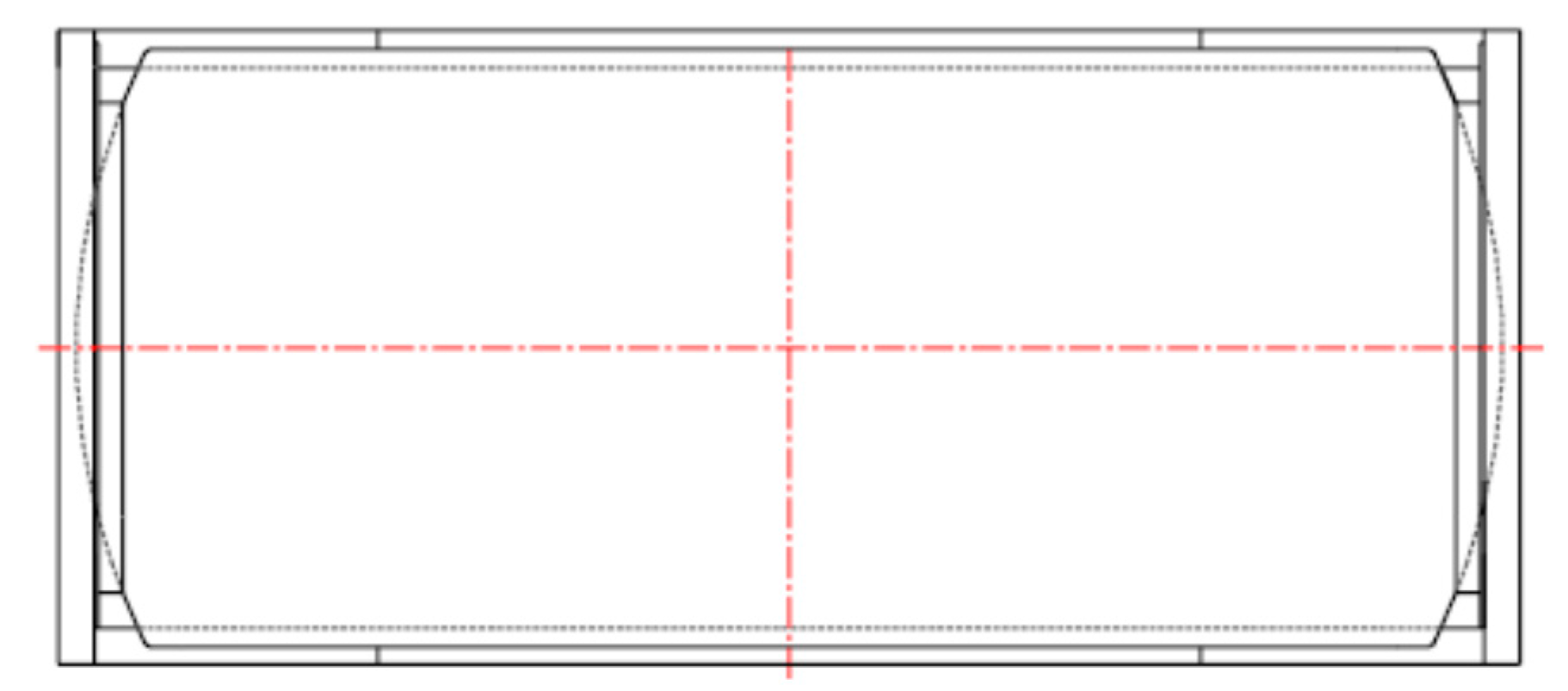
Figure 4.
Upper view.

Figure 5.
Front view.

Figure 6.
Displacements along y.

Figure 7.
Displacements along x.

Figure 8.
Displacement along z.

Figure 9.
Plot of the maximum equivalent stress for the considered structure.

Figure 10.
Nodal displacements.

Figure 11.
The equivalent stresses calculated according to Von Mises.

Figure 12.
Nodal displacement.

Figure 13.
Equivalent stress.

Figure 14.
Nodal displacements.

Figure 15.
Equivalent stress.

Figure 16.
Nodal displacements.

Figure 17.
Equivalent stress (Von Mises).

Figure 18.
Nodal displacements.

Figure 19.
Equivalent stresses (Von Mises).

Figure 20.
Maximum equivalent tension.

Figure 21.
Maximum equivalent tension reducing the thickness of the plate and the skirt by 5 mm.

Figure 22.
Condition with maximum stress value.


Table 1.
ISO standard test on tank container.
| N° Test |
|---|
| 1 Stacking |
| 2 Lifting for upper corner blocks |
| 3 Lifting for lower corner blocks |
| 4 Transverse stiffness |
| 5 Longitudinal stiffness |
| 6 Restraint |
Table 2.
Stacking test results.
| Upright | Displacement along x(mm) | Displacement along y(mm) | Displacement along z(mm) |
|---|---|---|---|
| A | 0.65 | 2.00 | 0.27 |
| B | 0.7 | 2.26 | 0.52 |
| C | 0.6 | 2.18 | 0.45 |
| D | 0.7 | 2.16 | 0.43 |
| mean | 0.66 | 2.15 | 0.42 |
Table 3.
Displacements detected during the lifting from the upper corner blocks.
| Element | Displacements (mm) |
|---|---|
| tank | 2.0 |
| spar | 1.8 |
Table 4.
Displacements detected during the lifting from the lower corner blocks.
| Element | Displacements (mm) |
|---|---|
| tank | 1.6 |
| spar | 1.5 |
Table 5.
Geometric and inertial characteristics.
| Dimension mm | Thickness mm | Mass Kg/m | Section cm2 | Moment of Inertia cm4 | Moment of Inertia of Torsion cm4 | |
|---|---|---|---|---|---|---|
| uprights | 150 × 150 | 20 | 70.2 | 98.0 | 2795 | 4726 |
| spar | 180 × 100 | 12 | 47.0 | 59.9 | Ixx = 2320 Iyy = 886 | 2130 |
| Supports Corner | 140 × 80 | 10 | 30.6 | 38.9 | Ixx = 908 Iyy = 362 | 862 |
Table 6.
Yield and allowable stress of the two types of steel used.
| Element | Material | Yield Stress | Allowable Stress |
|---|---|---|---|
| Tank | 316L steel | ||
| Frame | Fe510D steel |
Table 7.
Case 1: Values of the natural frequencies of vibrations, in Hertz- empty tank.
| Mode 1 | Mode 2 | Mode 3 | Mode 4 | Mode 5 |
| 3.54 | 12.27 | 18.99 | 25.79 | 26.22 |
| Mode 6 | Mode 7 | Mode 8 | Mode 9 | Mode 10 |
| 27.23 | 30.44 | 30.52 | 32.43 | 32.57 |
Table 8.
Case 2: Natural frequencies tank water filled.
| MODE 1 | MODE 2 | MODE 3 | MODE 4 | MODE 5 |
|---|---|---|---|---|
| 1.847 | 2.752 | 3.623 | 3.923 | 3.925 |
Table 9.
Comparison between the results provided by the manufacturer and those resulting from the FEM analysis.
Table 9.
Comparison between the results provided by the manufacturer and those resulting from the FEM analysis.
| N° | TEST | Element | Real Values (mm) | FEM Value (mm) | Error % |
|---|---|---|---|---|---|
| 1 | stacking | Upright | Ux = 0.66 | 0.58 | 12% |
| Uy = 2.15 | 2.0 | 7% | |||
| Uz = 0.42 | 0.18 | 57% | |||
| 2 | Top Lift | tank | Usum = 2.0 | 1.0 | 50% |
| spar | Usum = 1.8 | 1.8 | 0% | ||
| 3 | Lower Lift | tank | Usum = 1.6 | 0.8 | 50% |
| spar | Usum = 1.5 | 1.6 | 6% | ||
| 4 | Transverse Stiffness | Upright | Usum = 3.0 | 2.4 | 20% |
| 5 | Longitudinal stiffness | Upright | Usum = 15.0 | 14.0 | 7% |
| 6 | Restraint | Upright | Usum = 4.0 | 3.4 | 15% |
Publisher’s Note: MDPI stays neutral with regard to jurisdictional claims in published maps and institutional affiliations. |
© 2021 by the authors. Licensee MDPI, Basel, Switzerland. This article is an open access article distributed under the terms and conditions of the Creative Commons Attribution (CC BY) license (http://creativecommons.org/licenses/by/4.0/).
Share and Cite
MDPI and ACS Style
Liguori, A.; Formato, A.; Pellegrino, A.; Villecco, F. Study of Tank Containers for Foodstuffs. Machines 2021, 9, 44. https://0-doi-org.brum.beds.ac.uk/10.3390/machines9020044
AMA Style
Liguori A, Formato A, Pellegrino A, Villecco F. Study of Tank Containers for Foodstuffs. Machines. 2021; 9(2):44. https://0-doi-org.brum.beds.ac.uk/10.3390/machines9020044
Chicago/Turabian StyleLiguori, Aurelio, Andrea Formato, Arcangelo Pellegrino, and Francesco Villecco. 2021. "Study of Tank Containers for Foodstuffs" Machines 9, no. 2: 44. https://0-doi-org.brum.beds.ac.uk/10.3390/machines9020044
Note that from the first issue of 2016, this journal uses article numbers instead of page numbers. See further details here.