Article

Analysis of the Influence of Textured Surfaces and Lubrication Conditions on the Tribological Performance between the Compression Ring and Cylinder Liner

by
Carlos Pardo García
1,
Jhan Piero Rojas
2 and
Sofia Orjuela Abril
3,*
1
Programa de Ingeniería de Sistemas, Universidad Francisco de Paula Santander, Avenida Gran Colombia No. 12E-96 Barrio Colsag, San José de Cúcuta 540001, Colombia
2
Facultad de Ingeniería, Universidad Francisco de Paula Santander, Avenida Gran Colombia No. 12E-96 Barrio Colsag, San José de Cúcuta 540001, Colombia
3
Programa de Administración de Empresas, Universidad Francisco de Paula Santander, Avenida Gran Colombia No. 12E-96 Barrio Colsag, San José de Cúcuta 540001, Colombia
*
Author to whom correspondence should be addressed.
Submission received: 26 March 2021 / Revised: 21 April 2021 / Accepted: 2 May 2021 / Published: 6 May 2021
(This article belongs to the Special Issue Advances in Tribology and LCA Applied to Thermal Machines)

Abstract

:
The objective of the present investigation is to analyze the tribological performance between the union of the cylinder liner and the compression ring under the influence of surface texturing and different lubrication boundary conditions. The analysis is carried out by developing a numerical model, which involves hydrodynamic pressure, lubrication film thickness, textured surface, dynamic forces, and lubrication boundary conditions (starved lubrication and fully flooded lubrication). MATLAB® software (The MathWorks Inc., Natick, MA, USA) is used to solve the equations developed. The results show that the application of a textured surface on the cylinder liner allows obtaining a reduction of 20% and 5% in the asperity contact force and in the total friction force. Additionally, the textured surface allows for a 4% increase in MOFT. In this way, it is possible to reduce the power loss. The implementation of a boundary condition of fully flooded lubrication produces an overestimation in the total friction force due to the greater prominence of the lubrication film. Implementing a textured surface in the ring profile is an alternative way to reduce power loss. The results show that this alternative allows an 8% reduction in power loss.

1. Introduction

Despite the negative climatic changes that the planet is experiencing and the progressive reduction of fossil resources, fuels from fossil materials continue to represent a high percentage as one of the main sources of energy used [1,2]. The studies carried out show that to control and mitigate climate change, it is necessary to reduce harmful emissions. Specifically, it is necessary to achieve a 60% reduction in pollutant emissions by 2050 in order to effectively mitigate the planet’s environmental problems [3,4]. This is a great challenge, as internal combustion engines (ICE) are expected to remain relevant for decades to come [5]. This situation has generated the investigation of alternatives that allow reducing emissions and saving fuel [6]. Among the strategies to improve the efficiency of ICE are changes in mechanical design, operating conditions, and the use of alternative fuels [7,8]. Approximately between 4% and 15% of the energy of the fuel is used to overcome the friction processes of a four-stroke IC engine [9,10]. The interaction between the cylinder liner and the piston rings represents between 40% and 55% of the losses caused by friction [11]. This implies that the reliability, performance, and useful life of the engine are strongly influenced by the working conditions in the union between the cylinder liner and the piston ring. The conditions in this joint depend on the lubrication characteristics [12]. Therefore, tribological studies are necessary to search for an improvement in fuel economy and a reduction in harmful emissions. The reduction of these parameters is relevant due to the increasing energy cost due to the constant decrease in fossil resources [13], which has a direct impact on the economics of internal combustion engines [14]. Additionally, fuel consumption plays a relevant role in the increase in temperature, given the greenhouse gases produced by the combustion process [15,16].
Different types of analytical and experimental studies focused on the piston are presented in the literature. In general, investigations focused on experimentation are difficult to carry out due to the high intrusion that must be carried out in the thermal machines for the measurement process under operating conditions [16,17,18]. Therefore, in recent years, the development of research based on analytical models has been chosen, which has allowed a deeper compression of the tribological behavior between the union of the cylinder liner and the piston rings [19,20]. Studies of this type include the research by Baker et al. [21], who studied the elastodynamics of piston rings and their effect on combustion gas leakage. Rahmani et al. [22] suggested that tribological characteristics influence fuel consumption and emissions. Additionally, it was observed that these parameters could be reduced by controlling the temperature of the cylinder diameter. Mishra et al. [23,24] developed a thermo-elastohydrodynamic model for the analysis of piston compression rings and the influence on friction losses. The results show that the properties of the lubricant cannot be ignored [25]. Morris et al. [26] used a thermal network model to predict the cylinder liner contact temperature. Using this model, the influence of ring friction on piston temperature was investigated.
Normally, in IC engines, the lubricating oil film is thin, which implies that the upper piston ring is often in an insufficiently lubricated condition, as demonstrated by experimental investigations [27]. Under this condition, part of the surface area of the lining and piston rings are covered with a mixture of lubrication film and combustion gases. In recent years, the maximum pressure in the cylinder chamber has been increasing in engines, which causes the upper piston ring limit to be subjected to high pressures. This causes the top ring to tend to a mixed oil–gas state during the combustion cycle.
Under the condition of insufficient lubrication, it is necessary to determine the rupture position and the inlet of the lubrication film. This is simple when considering a completely flooded boundary condition [28] since the inlet position coincides with the edge of the piston ring. In insufficient lubrication conditions, the film inlet position depends on cavitation [29]. Priest [30] investigated the tribological behavior of the ring using four different cavitation models. Typically, the Reynolds boundary condition and Jakobsson Floberg Olsson (JFO) are the most widely used methods to consider the effect of cavitation in flooded lubrication conditions. However, experimental studies show that the piston compression ring is partially covered [31]. The investigation of Ma et al. [32] shows that for this condition, the analysis by open cavitation has a better agreement with the experimental results. Due to the above, different studies have used this approach in tribological analysis at the junction between the cylinder liner and the piston ring [33,34,35,36].
Current IC engines are considered highly efficient thermal machines. Therefore, to improve their performance, it is necessary to implement innovative technologies, such as heat treatment of exhaust gases, deactivation of cylinders, the use of advanced coatings, and surface texturing [37,38,39]. Among all these alternatives, surface texturing is considered a potential method to improve the tribological performance of the engine [40]. This method consists of an intentional modification of the surface topography, applying features such as grooves and dimples. The use of this type of texture allows the storage of lubricant and particles, allowing a reduction in friction [41].
The studies carried out indicate that the modification of the surface plays a relevant role in the tribological properties of the areas exposed to contact in the internal combustion engine. The construction of micro-textures in the cylinder liner, piston ring, and bearings is an alternative to reduce wear and extend the useful life of the components [42]. Surface texturing can be applied using laser techniques, which have proven to be advantageous due to their high level of control and precision in establishing geometric dimensions [43]. Lubricant storage in textured areas favors interaction between surfaces, especially under high load conditions. In addition, the textured areas allow you to collect or trap wear particles. Due to the above characteristics, surface modification is a viable technique to seek to improve the tribological properties of sliding surfaces.
At present, several investigations have focused on the analysis of the textured surface for its low friction capacity [44,45,46]. Babu et al. [46] evaluated the tribological characteristics applied to the piston ring with different dimple sizes. The results indicate a reduction in friction. Additionally, it was observed that a 72% decrease in the wear rate of the cylinder liner is possible compared to a non-textured surface on the ring profile. Mishra et al. [47,48] investigated the effect of a laser textured surface. The results show that the change in tribological film formation and the hydrodynamic effect of dimples contribute to better lubrication performance when additives are used. However, a large part of the investigations focused on the analysis of surface texture are carried out considering a condition of total flooding, which is not very consistent with the experimental results.
Due to the above, in the present study, an analysis of the influence of the surface texture applied to the cylinder liner and the profile of the compression ring on the tribological performance is carried out. For this, a numerical model is built, which considers the properties of the lubricant, the hydrodynamic pressure, and the dynamic forces. Additionally, the effect of the boundary lubrication condition in a state of fully flooded lubrication and starved lubrication is evaluated in the estimates of MOFT and power loss.

2. Materials and Methods

This section aims to describe the equations used to develop the numerical model used in this research.

2.1. Lubrication Film Properties

The properties of the lubricant significantly influence the tribological characteristics at the junction between the cylinder liner and the piston ring. Additionally, the properties of the lubricant depend on different physical factors. The Dowson and Higginson model [49] is used to define the density of the lubricant ( ρ ) , as shown in Equation (1):
ρ = ρ o · ( 1 c t · [ T T o ] ) · ( 1 + 0.6 × 10 9 P 1 + 1.7 × 10 9 P )
where c t is the thermal expansion coefficient ( K 1 ) , T is the temperature ( K ) , and P is the pressure of the lubrication film ( Pa ) . The subscript o indicates the ambient reference conditions.
The lubricant used as the basis for the calculation is SAE 15W-40 since the properties of this lubricant allow reducing wear and corrosion processes (see Table 1). Additionally, it facilitates the dispersion of particulate material, maintains its stability at high temperatures, and provides high longevity in extreme operating conditions. The above characteristics favor fuel economy and allow to maintain a low coefficient of friction [50]. To characterize the viscosity of the lubricant ( μ ) , the Reolands’s model [50] and Houpert’s model [51] are used together, as shown in Equation (2):
μ = μ o · e ln ( μ o μ ) · [ ( P P o c p + 1 ) z ( T 138 T o 138 ) s 1 ]
where, μ o = 0.221   Pa · s is the dynamic viscosity of the lubricant under ambient conditions. The terms s and z are the thermo-viscosity indices and lubricant piezo-viscosity, respectively. s and z are calculated by Equations (3) and (4):
s = ( T o 138 ) · γ o ln ( μ o μ )
z = c p · α o ln ( μ o μ )
where α o = 10 8   m 2 / N and γ o are the piezo-viscosity and thermo-viscosity ( K 1 ) under ambient conditions. μ = 6.31 × 10 5   Pa · s and c p = 1.98 × 10 8   Pa are the model constants [50].

2.2. Lubrication Film Pressure

To determine the lubricant pressure, the Reynolds model derived from Patir, and Cheng [52] is used, which considers the effects of surface roughness. Equation (5) describes the model used:
6 v p · ϕ c · h x + 6 v p · σ · ϕ s x + 12 ϕ c · h t = x ( ϕ x · h 3 μ P x )
where v p is the piston velocity, σ is the composite roughness, and h is the lubrication film thickness. ϕ c ,   ϕ s , and ϕ x are the flow factors [53]. The composite roughness ( σ ) is determined from Equation (6):
σ = σ r 2 + σ c 2
where σ r 2 and σ c 2 are the surface roughness of the piston ring and cylinder liner, respectively.
The piston velocity ( v p ) is calculated considering the physical characteristics of the connecting rod-crank mechanism, as shown in Equation (7):
v p = ( 1 + cos θ ( l r ) 2 sin 2 θ ) · r · ω · sin θ
where r is the crank-pin radius, l is the connecting rod length, ω is the crankshaft angular velocity, and θ is the crank angle.
The Reynolds equation (Equation (5)) was discretized by means of the finite difference method. The discretized equation is solved using the Gaussian elimination method. To adjust the thickness of the lubrication film, the balance of dynamic forces is taken as a reference.

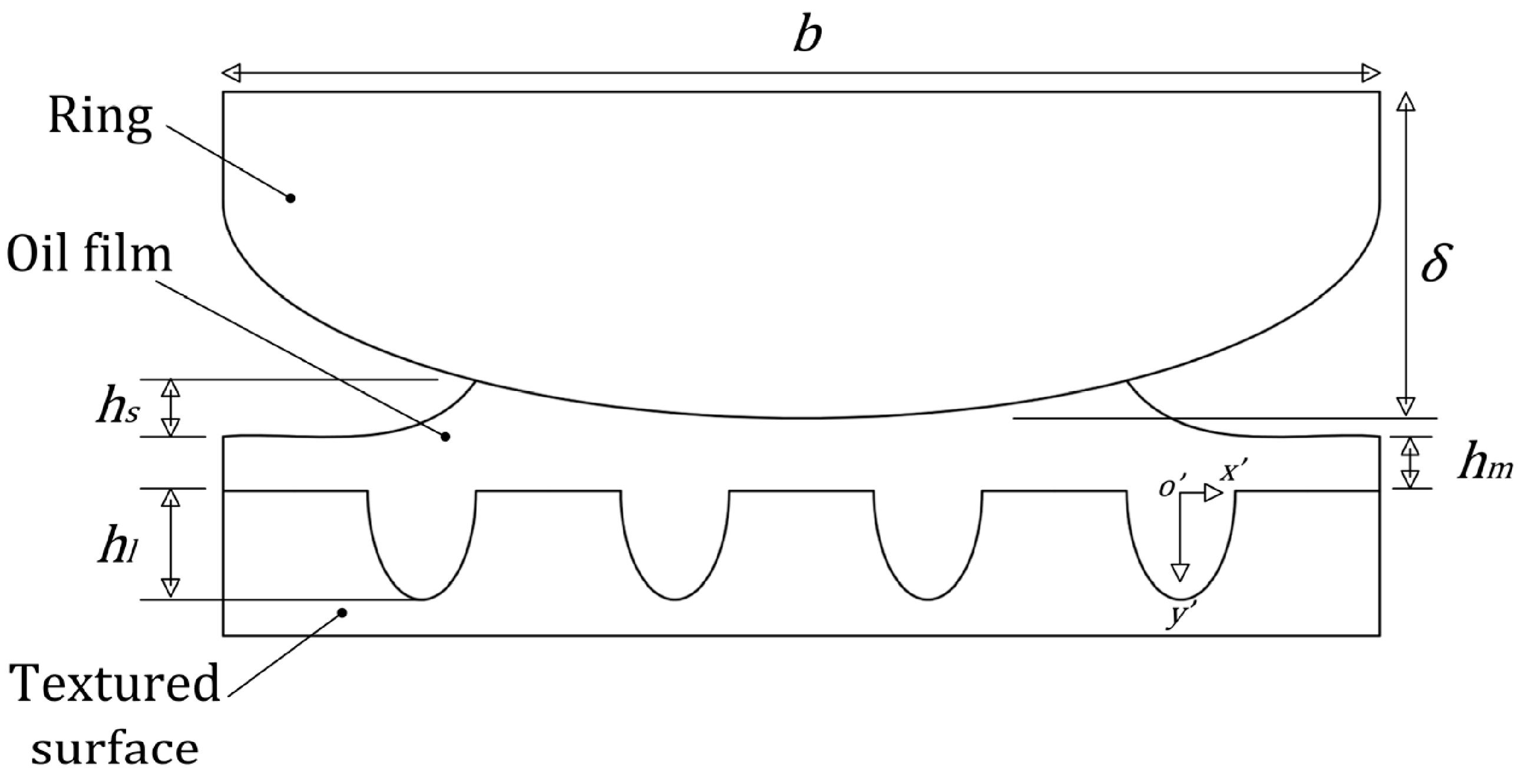
2.3. Lubrication Film Thickness

Since the distribution of the surface texture under the piston ring changes dynamically with the movement of the piston (see Figure 1), it is necessary to establish the thickness of the lubrication film between the cylinder liner and the piston ring as a function of the time and position, as shown in Equation (8):
h ( x , t ) = h m + h l ( x , t ) + h s ( x )
where h m is the minimum oil film thickness (MOFT), h l ( t , x ) is the height of the groove, and h s is the height of the ring profile. h l ( t , x ) and h s are calculated using Equations (9) and (10):
h l ( x , t ) = h g · sin ( π [ 1 2 + x r g ] ) 2 + h g · ( x v p · t ) 2
h s ( x ) = 4 δ · x 2 b 2
where h g is the average groove depth, 2 r g is the average groove width, b is the width of the ring face, and δ is the crown height of the ring. x represents the axial direction in the local coordinates of the groove.

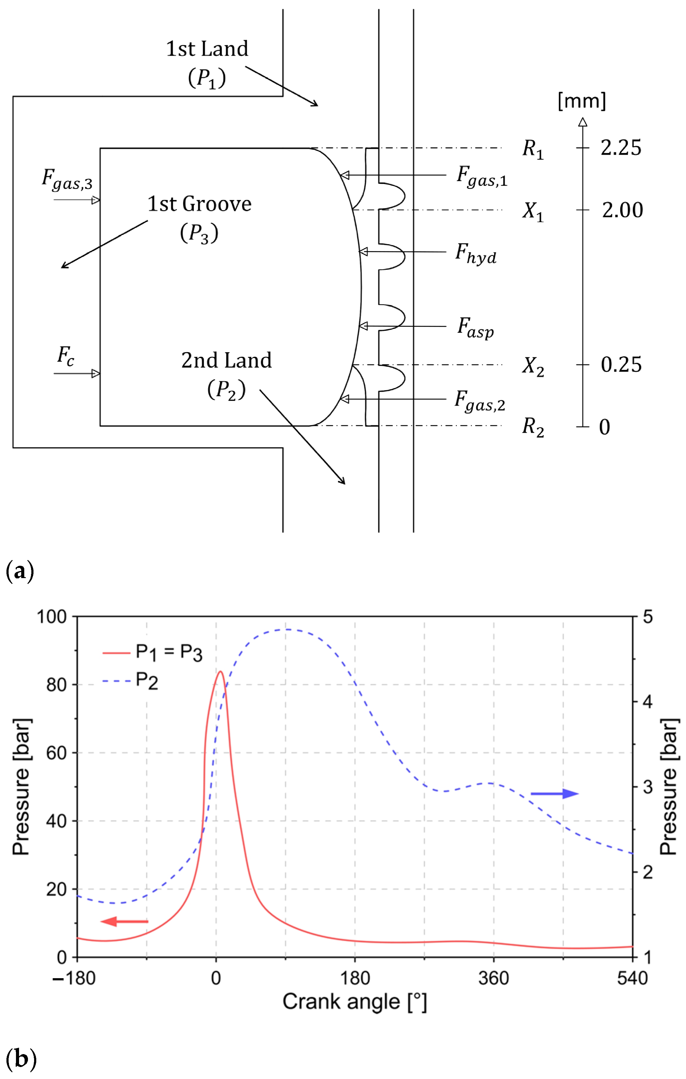
2.4. Piston Ring Dynamics

Figure 2 shows the forces acting between the cylinder liner and the surface of the piston ring. The dynamic equilibrium equation in the radial direction is shown below.
F g a s , 1 + F g a s , 2 + F a s p + F h y d = F g a s , 3 + F c
where F g a s , i is the force produced by the pressure of the gas at location i = 1 , 2 , 3 (Figure 2a). The term F g a s , i refers to the force of the combustion gases acting on the inner face of the ring due to the pressure of the combustion gases at the locations P 1 ,   P 2 , and P 3 = P 1 . To determine the magnitudes of these pressures, the experimental measurements of the pressure in the combustion chamber at the top and bottom of the piston ring are taken as a reference (see Figure 2b). The difference between the pressures, P 1 and P 2 , is a consequence of the significant reduction in the clearance between the piston groove and the compression ring, which is an indication of the sealing capacity of the ring. This result is in agreement with that reported in the literature [54]. Although there is also a reduction in clearance between the first land and first groove, this is not enough to cause an appreciable pressure drop in the combustion gases. The design of the piston grooves is intended to avoid an appreciable pressure drop between these two areas since the pressure in the groove favors the seal between the cylinder liner and the surface face of the ring. Therefore, for the present study, it is considered that P 1 = P 3 . The previous consideration coincides with the experimental measurements made by Tamminen et al. [55] and the computational analysis developed by Lyubarskyy and Bartel [56].
F c is the compression force due to the installation of the ring in the piston, F a s p is the asperity contact force, and F h y d is the hydrodynamic force.
The forces due to the pressure of the combustion gases ( F g a s , 1   ,   F g a s , 2   ,   F g a s , 3   ) are calculated using the Equations (12)–(14):
F g a s , 1 = P 1 · ( R 1 X 1 )
F g a s , 2 = P 2 · ( R 2 X 2 )
F g a s , 3 = P 3 · ( R 1 R 2 )
where X 1 is the film inlet position, X 2 is the film rupture position, R 1 is the leading of the ring, and R 2 is the trailing of the ring.
The compression force ( F c ) is calculated from Equation (15) [57]:
F c = σ t · b 2 · A 3 D · ( D b )
where D and A are the diameter and cross-section of the ring. σ t is the bending stress, which is calculated by Equation (16):
σ t = 3 E · b · f 2 L 2
where E ,   L , and f are the ring modulus of elasticity, the ring length, and the ring gap at free conditions.
The hydrodynamic force ( F h y d ) and asperity contact force ( F a s p ) are calculated from Equations (17) and (18). The pressure distribution ( P ) of the lubrication film used in Equation (17) is obtained from the Reynolds equation. The Greenwood and Tripp model is used to estimate the asperity contact force [58].
F h y d = X 2 X 1 ( h 2 · P x + v p · μ h ) d x
F a s p = 16 π 2 15 · ( ξ · κ · ς ) 2 · ς κ · E · A · F 5 / 2
The parameters κ ,   ς , and ξ represent the average asperity tip radius of curvature, the composite surface roughness of the contiguous surfaces, and the asperity distribution per unit contact area. E , A , and F 5 / 2 are the effective Young’s modulus of elasticity of the contact, the area of contact, and the statistical function of lubricant film ratio. Equations (19) and (20) are used to determine the parameters E and F 5 / 2 [59]:
1 E = 1 v 1 2 E 1 + 1 v 2 2 E 2
F 5 / 2 = { 0.0046 λ 5 + 0.0574 λ 4 0.2958 λ 3 + 0.7844 λ 2 1.0776 λ + 0.6167 ,       λ 2.224 0 ,       λ > 2.224 }
where ν is the Poisson’s ratio of the piston ring ( ν 1 ) and cylinder liner ( ν 2 ) . λ is the Stribeck’s lubricant film ratio, which is calculated by Equation (21):
λ = h ς
The total friction force ( F t f ) is composed of the sum of the shear force ( F s ) due to the viscosity of the lubrication film and the boundary force ( F b ) due to the roughness interaction, as shown in Equation (22):
F t f = F s + F b
where F s and F b are calculated using Equations (23) and (24):
F s = τ · ( A A e )
F b = τ o · A e + ζ · F a s p
where τ is the viscous shear stress of the lubricant, A e is the real area of contact area, τ o is the limiting Eyring shear stress of the lubricant, and ζ = 0.17 is the coefficient of asperity shear strength [60]. τ is calculated using Equation (25) [25]:
τ = | μ h v p ± h 2 P |
The real area of contact area ( A e ) is calculated by Equation (26):
A e = π 2 ( ξ · κ · ς ) 2 · A · F 2
where F 2 is a statistical function of the Stribeck’s lubricant film ratio [59], calculated as:
F 2 = { 0.0018 λ 5 + 0.0281 λ 4 0.1728 λ 3 + 0.5258 λ 2 + 0.5003 ,         λ 2.295 0 ,         λ > 2.295 }
The power loss ( W ˙ l o s s ) caused by the total friction force is determined by Equation ( 28 ) :
W ˙ l o s s = | F t f · v p |

2.5. Boundary Conditions

For a fully flooded lubrication condition, the inlet boundary condition can be determined by Equations (29) and (30) since the joint between the cylinder liner and the piston ring is completely covered:
X 1 = R 1
P ( X 1 ) = P 1
In the case of a starved lubrication condition, it is necessary to determine the characteristics of the textured surface and the thickness of the available lubrication film. Additionally, it is necessary to consider that the texturing characteristics change over time. Equations (31)–(33) are used to determine the inlet boundary condition with and without a textured surface:
P ( X 1 ) = P 1
q ( X 1 , t ) = q s u p p l y ( X 1 , t )
q s u p p l y ( X 1 , t ) = { v p · ( h s u p p l y + h l ) ,       textured v p · h s u p p l y ,         untextured }
where q ( X 1 , t ) is the flow lubricant flow rate, h s u p p l y is the lubricant film thickness available, and q s u p p l y ( X 1 , t ) is the lubricant supply flow rate.
The outlet boundary conditions are determined by Equations (34) and (35):
P ( X r ) X = 0
P ( X r ) = P 2

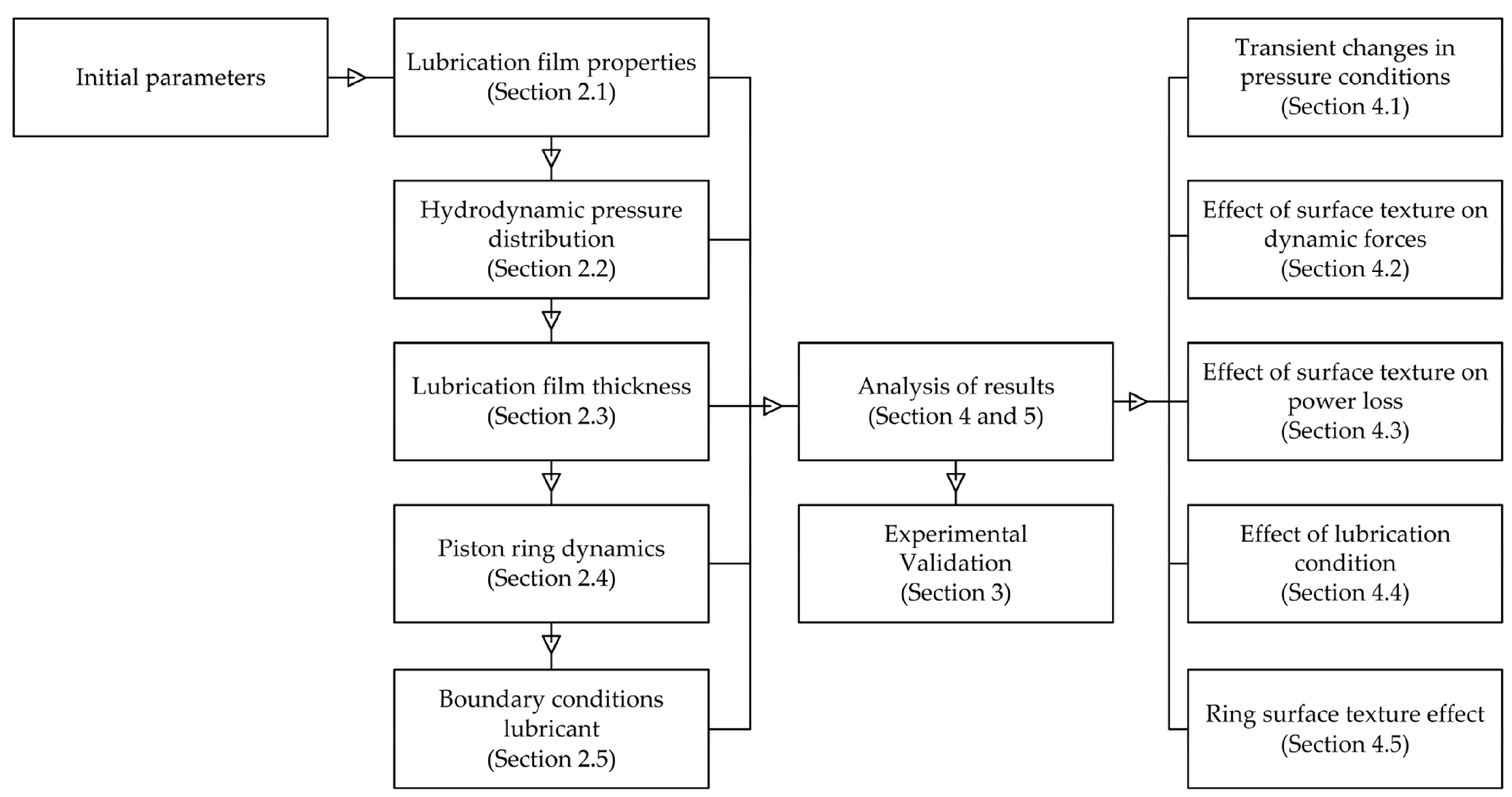
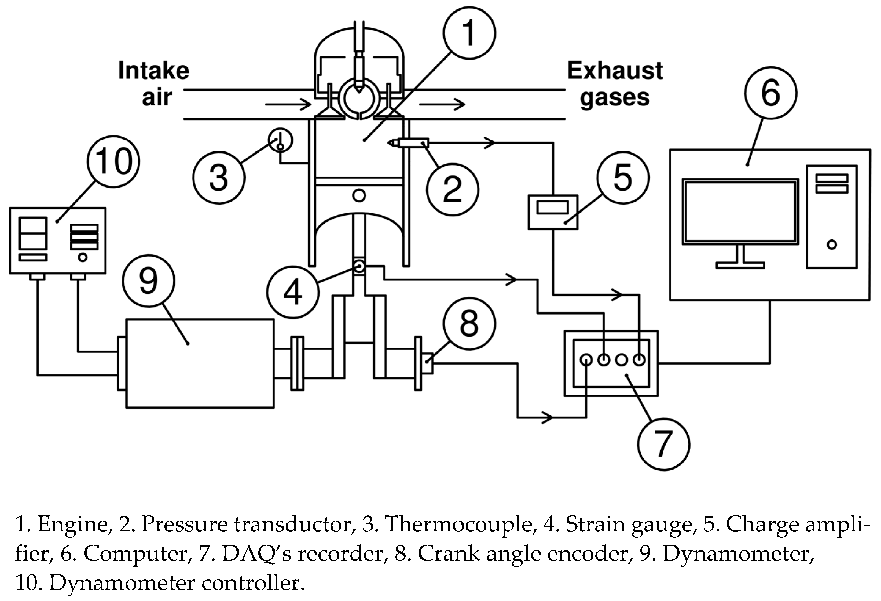
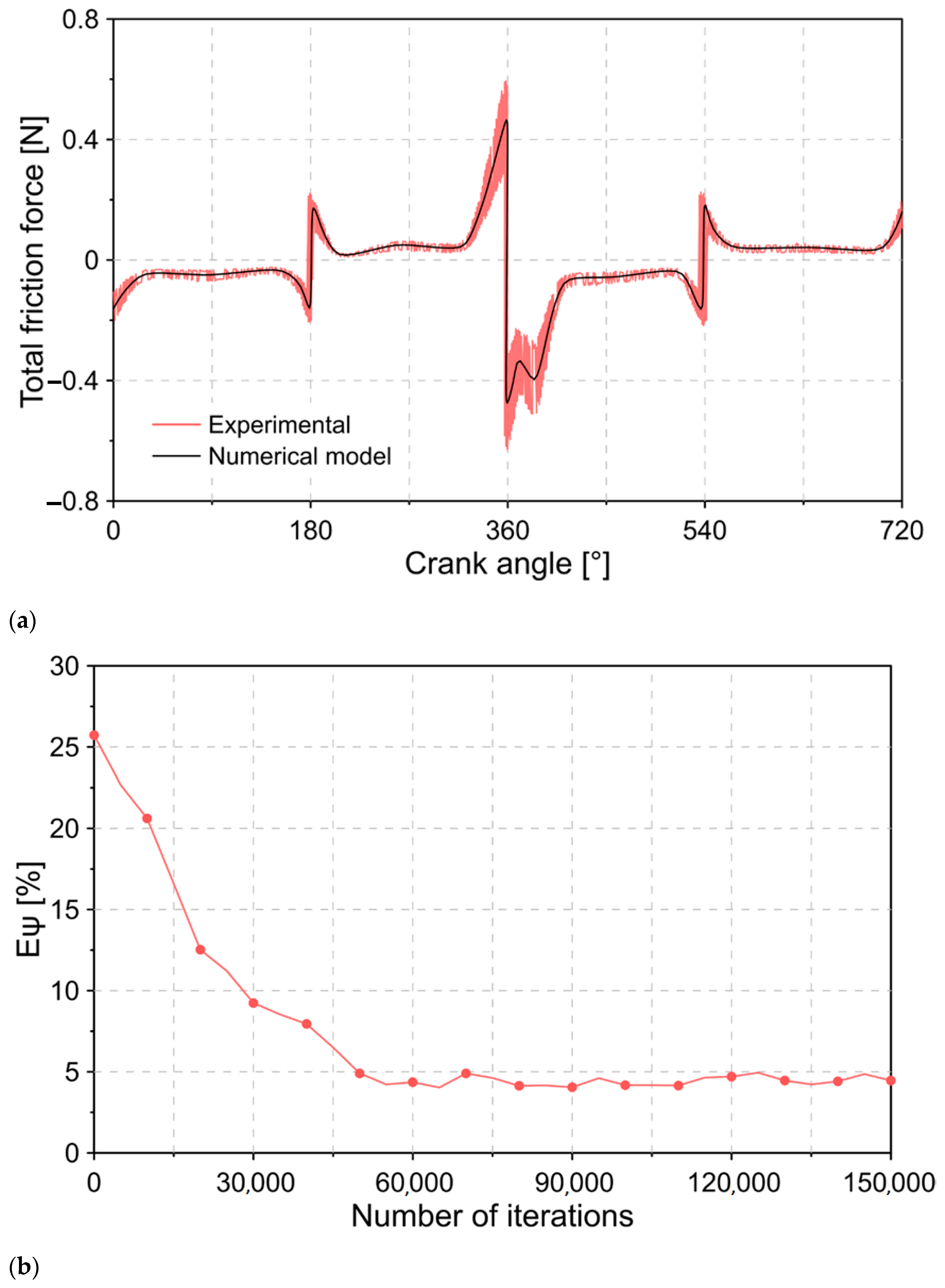
3. Numerical Procedure

Figure 3 describes the procedure implemented to solve the equations described in Section 2. The solution of the system of equations is carried out using the solver ode45 of the MATLAB software.
The first step is to establish the initial parameters, such as position, initial lubrication film thickness, properties, and environmental conditions. Subsequently, the Reynolds equation is solved to determine the pressure distribution. The inlet and outlet position of the lubrication film is estimated by Equations (29)–(35). Finally, the dynamic behavior of the ring is established by the equations of Section 2.4. Table 1 shows the geometric parameters of the engine used as a reference. The characteristics of the textured surface are described in Table 2.
To validate the estimates obtained by means of the numerical model, a comparison is made between the simulated friction force and the experimentally measured force. This friction force is determined indirectly by applying the IMEP (indicated mean effective pressure) method [61]. For the measurement system, two strain gauges (KFG-1-120-D16-11L1M2S) installed in the connecting rod body are used. Installation is done using cyanoacrylate resin adhesive (CC-33A) with high mechanical and thermal resistance. The pressure in the combustion chamber is carried out by means of a piezoelectric transducer (KISTLER type 7063-A) installed in the cylinder head. The position of the crankshaft is measured by an angle sensor (Beck Arnley 180-0420). The textured surface on the cylinder liner was made using the Nd:YAG laser. The textured surface was measured with the HOMMEL TESTER T1000 roughness tester. The diagram of the measurement system is shown in Figure 4.
For the uncertainty analysis, the Type A evaluation method was implemented, in which statistical analysis of a series of measurements is considered ( y 1 , y 2 , y 3 y n ) . To define the most appropriate measurement in this series, Equation (36) is used:
y ¯ = i = 1 n y i n
The uncertainty calculation is performed using the standard deviation, as indicated in Equation (37):
μ s = i = 1 n ( y i y ¯ ) 2 n · ( n 1 )
For the experimental tests, a total of three repetitions were carried out in each measurement ( n = 3 ) since a greater number of measurements could increase the uncertainty due to the longer experimentation time required. The characteristics of the measuring instruments and the uncertainty are shown in Table 3.
The comparison between the friction force obtained experimentally and through the numerical model is shown in Figure 5. The results show that the model estimates coincide with the trend of the experimental measurements. The maximum relative error between both sources remained below 20%.
Additionally, Figure 5 shows that the greatest magnitudes of the friction force are located at crankshaft angles of 180° and 540°, which correspond to the top dead center and bottom dead center in the piston stroke. During these locations, the speed of the piston decreases significantly due to the change in the direction of movement, producing a reduction in the entrainment velocity of the lubricant and, therefore, an increase in the coefficient of friction. Similar results are reported in the literature [62]. The possibility of wear increases with the cessation of lubricant entrainment velocity during piston reversals, and the power loss is exacerbated in these regions.
The results of Figure 5a show that the estimates of the numerical model are in agreement with the real behavior of the total friction force. Therefore, numerical models can be a suitable tool for the analysis of the influence of textured surfaces. However, the accuracy of the numerical models is limited by the percentage of error that must be accepted in order to achieve convergence in the results. The previous drawback can be minimized by increasing the complexity of the numerical model.
To evaluate the robustness of the numerical model, a convergence analysis is carried out. The verification of the convergence of the model is defined by Equation (38), in which the relative error between two successive iterations ( E ψ ) is expressed:
E ψ = F t f n + 1 F t f n F t f n + 1 × 100 %
where n is the number of iterations. For the convergence analysis, the relative error was used when estimating the total friction force. The results obtained in Figure 5b show that after 50,000 iterations, the relative error remains less than 5%. It was observed that this trend is maintained throughout the following iterations.

4. Results

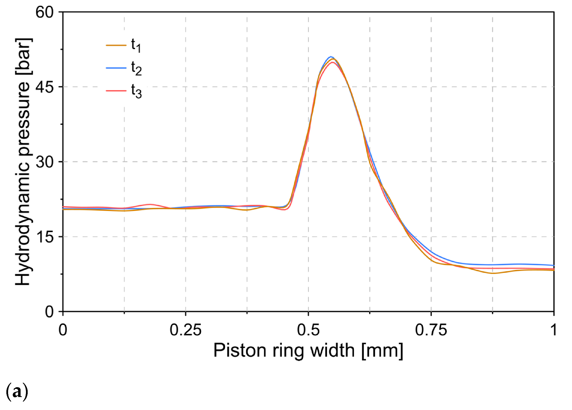
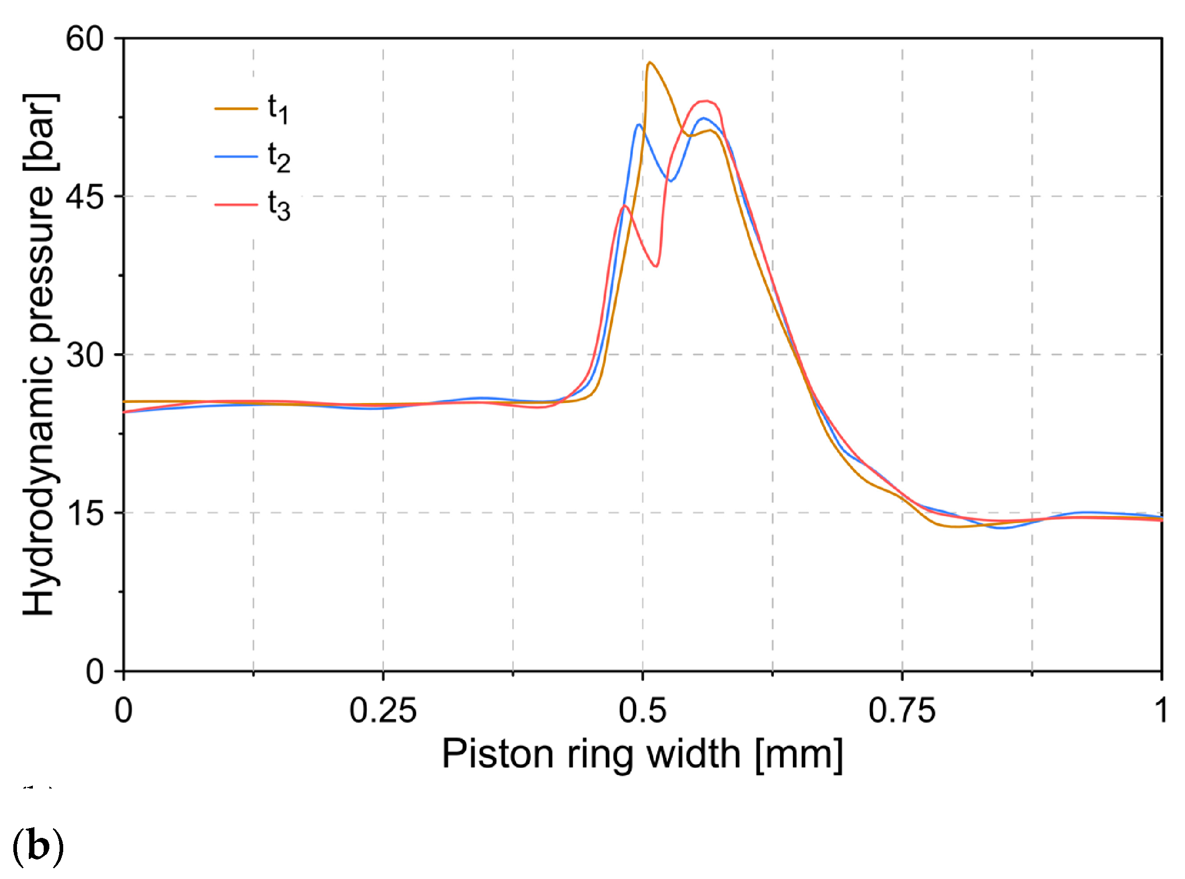
4.1. Transient Changes in Pressure Conditions

The constant movement of the piston causes the dynamic effects of the lubricant to change over time when applying textured surfaces. To evaluate this effect, Figure 6 describes the hydrodynamic pressure distribution for two different surface conditions in three instants of time (t1 = 5° crank angle, t2 = 25° crank angle, t3 = 125° crank angle), obtained through the numerical model.
The results in Figure 6a show that for an untextured surface, the pressure distribution does not change significantly over time. This is because the surface characteristics of the cylinder liner are kept constant. For the established conditions, maximum differences of 2.19% and 0.82% were observed when comparing state 1 (t1) with state 2 (t2) and state 3 (t3).
When establishing a textured surface condition, the results describe a change in hydrodynamic pressure (see Figure 6b), which is a consequence of the variation in the surface in contact with the piston ring. For the three states (t1, t2, t3) tested, maximum hydrodynamic pressures of 57.69, 54.42, and 53.99 bar, respectively, were recorded.

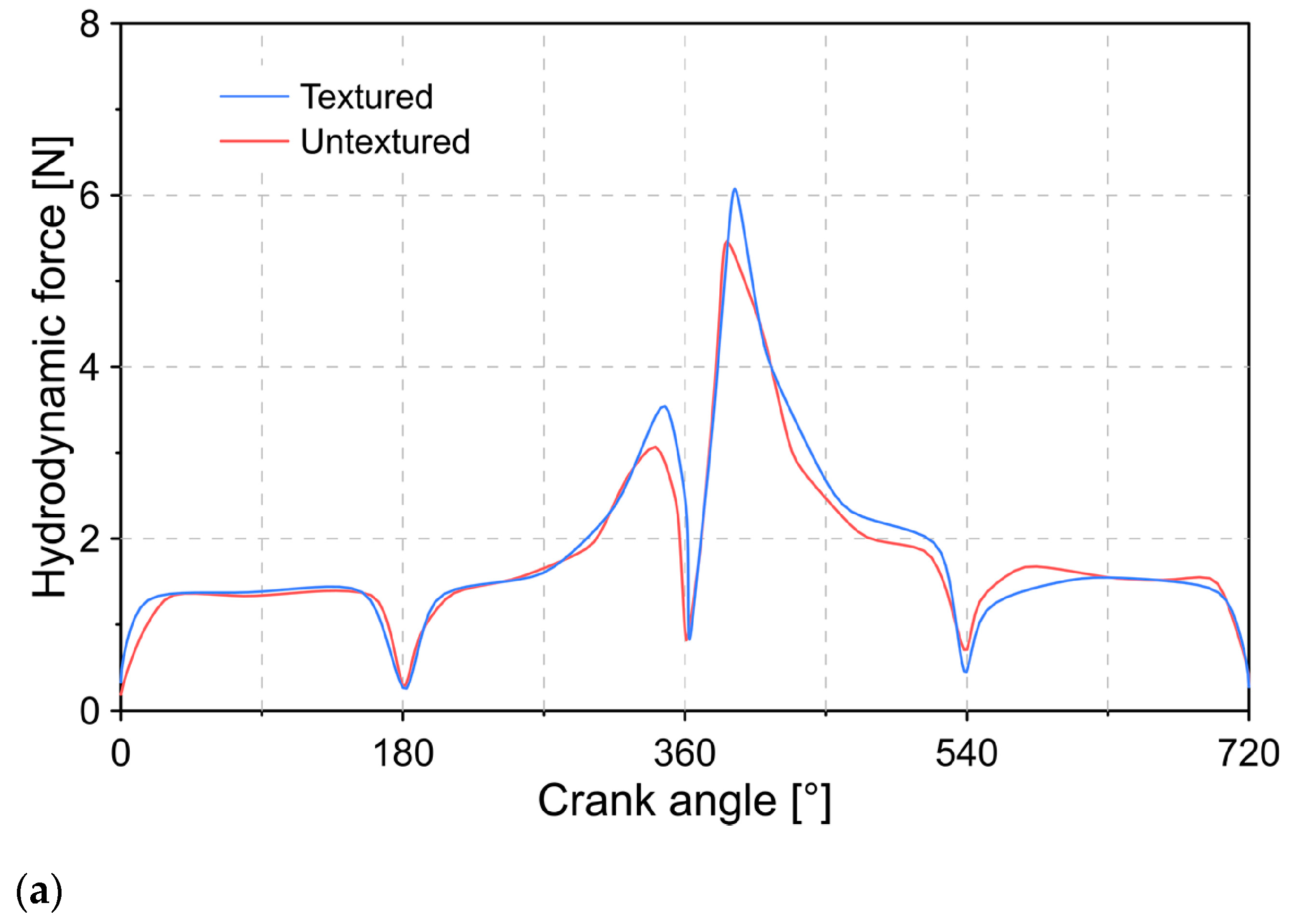
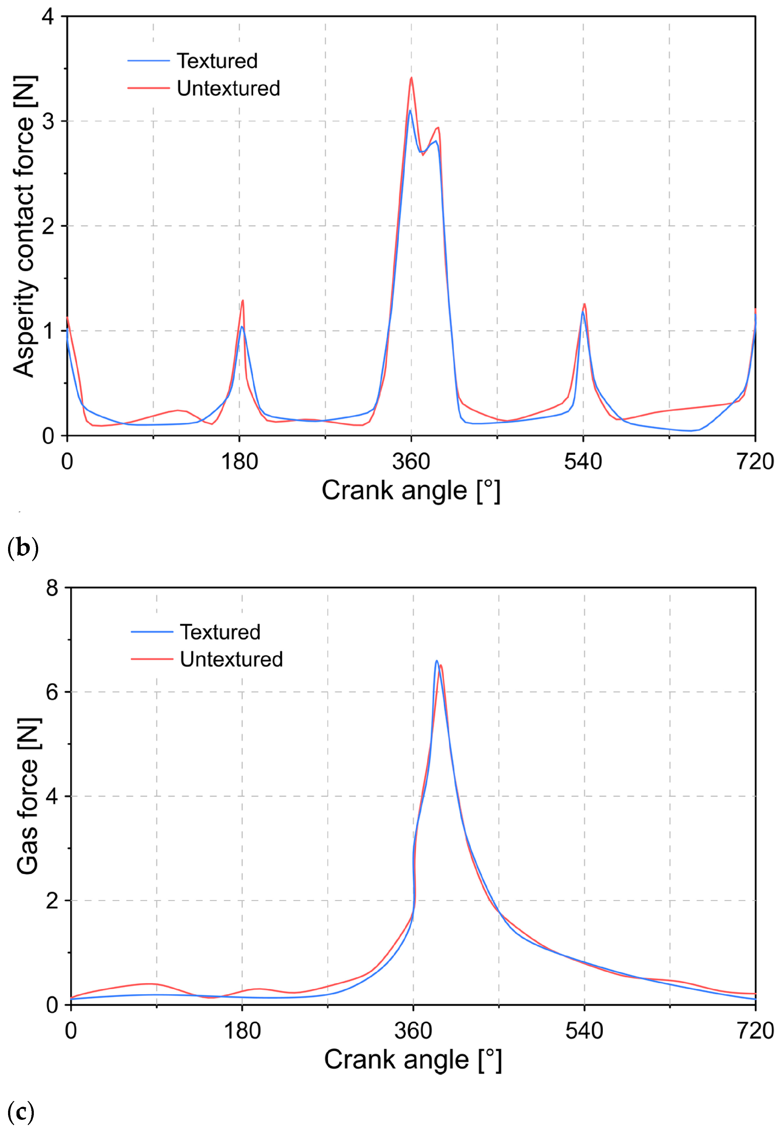
4.2. Effect of Surface Texture on Dynamic Forces

Figure 7 shows the behavior of the hydrodynamic force ( F h y d ) , the asperity contact force ( F a s p ) , and the force of the combustion gases ( F g a s ) for a condition with and without surface texture in the cylinder liner.
Figure 7a shows the behavior of the hydrodynamic force during the combustion cycle. The results show that the presence of the textured surface causes an increase in the hydrodynamic force, which may be a consequence of the larger contact area available. For the test conditions, maximum hydrodynamic forces of 5.47 N (untextured surface) and 6.07 N (textured surface), respectively, were obtained.
In the case of the asperity contact force (see Figure 7b), it was observed that the largest peaks occur at the angles of 180°, 360°, 540°, and 720°. The above locations correspond to the top dead center (TDC) and bottom dead center (BDC) of the combustion cycle. This behavior is attributed to the lower thickness of the lubrication film in these areas, as a consequence of the low velocity of the piston. For a textured surface, the peaks in the asperity contact force are 3.10, 2.81, 2.67, and 1.32 N. In the case of the untextured surface, peaks of 3.42, 2.94, 2.69, and 2.40 N were recorded. In general, the application of the texture in the cylinder liner causes a reduction in the roughness contact force.
When considering the force due to the pressure of the combustion gases, it was observed that the presence of a textured surface does not cause a considerable change in the magnitude of this force. In general, the maximum difference between both cases was less than 1.30%.
The change in dynamic forces due to surface texture will have an effect on the lubrication film. To evaluate this, Figure 8 describes the behavior of the minimum thickness of the lubrication film throughout the combustion cycle.
The results obtained show that the surface texture of the cylinder liner makes it possible to obtain a greater thickness in the lubrication film. The smallest thicknesses of the film are located in the TDC and BDC, which is in agreement with the results reported in Figure 7b. The maximum MOFT during the combustion cycle were 1.28 and 1.23 μ m for a textured and untextured surface.

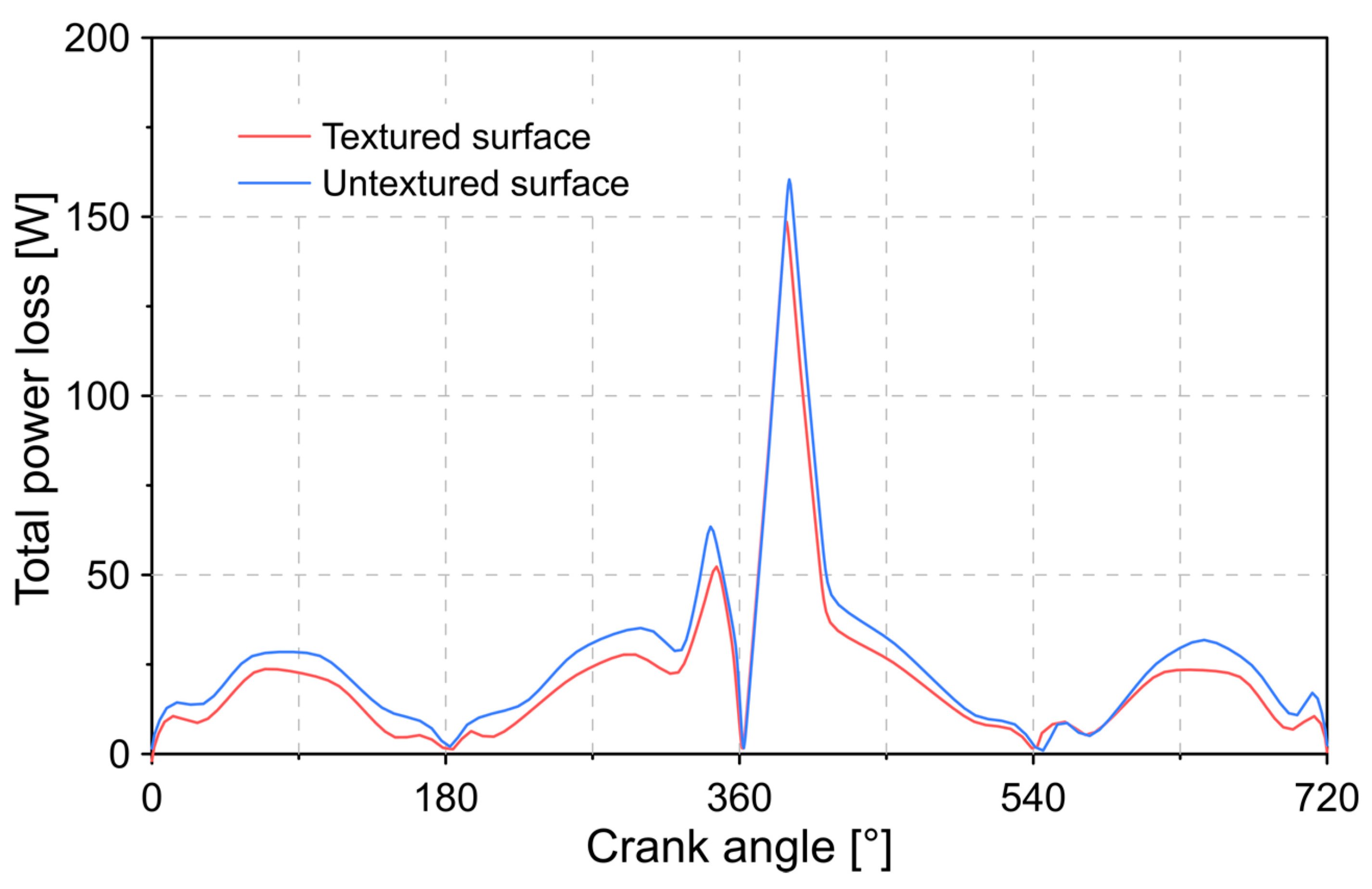
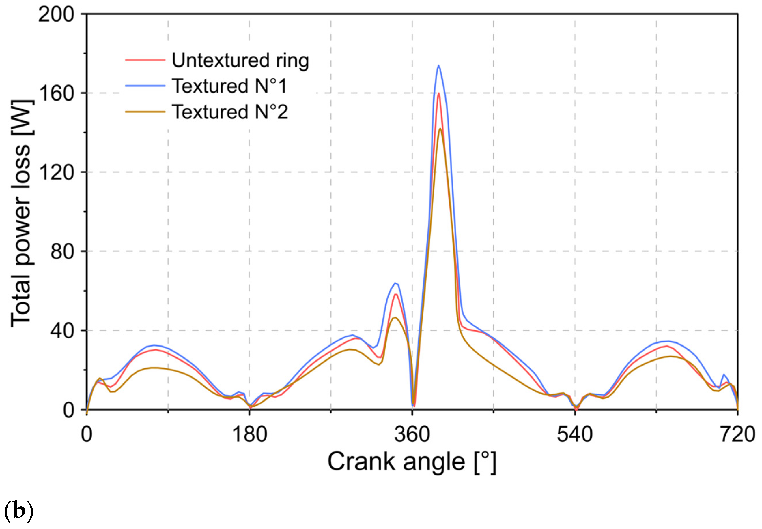
4.3. Effect of Surface Texture on Power Loss

Figure 9 shows the total friction force during the combustion cycle.
The results obtained in Figure 9 show that the texture in the cylinder liner allows the total friction force to be reduced. This is mainly attributed to the reduction in the roughness contact force, as shown in Figure 7b. In general, the presence of the texture results in a 15% reduction in the total friction force. The effect of the lower total friction force is reflected in a reduction in power loss, as shown in Figure 10. It was observed that for a surface condition without texture and with a textured surface, the maximum power loss was 160 and 149 W, respectively.

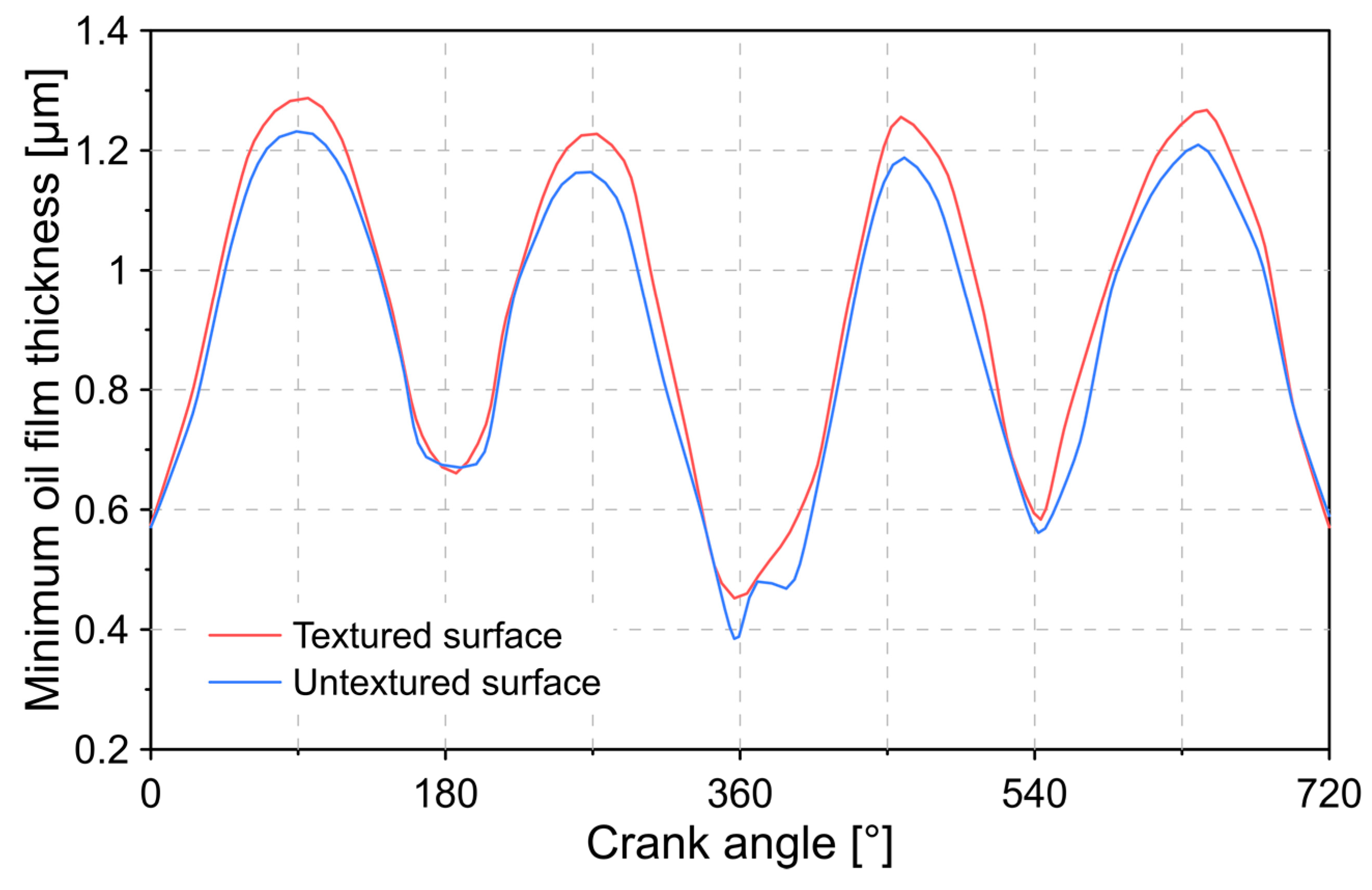
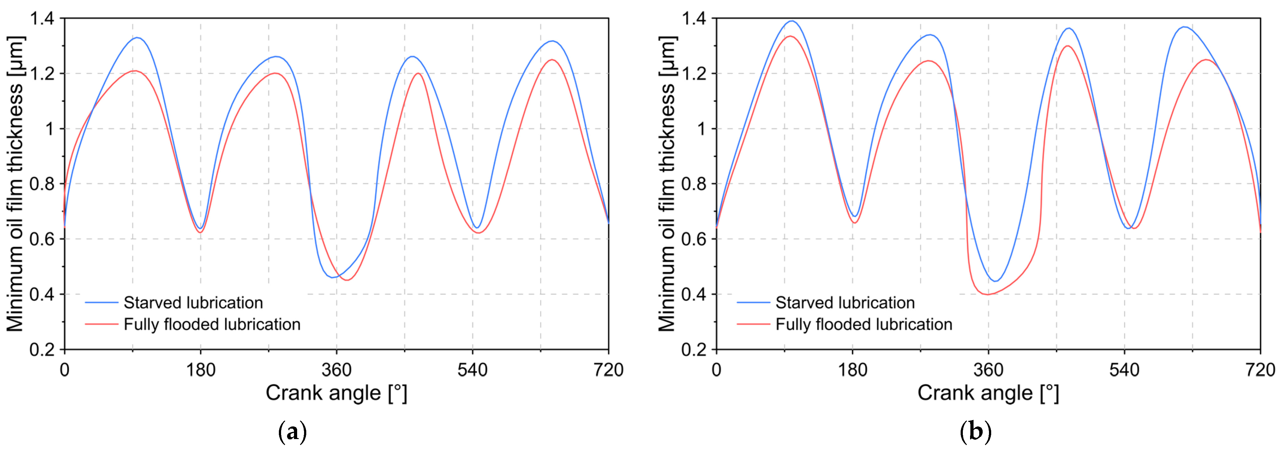
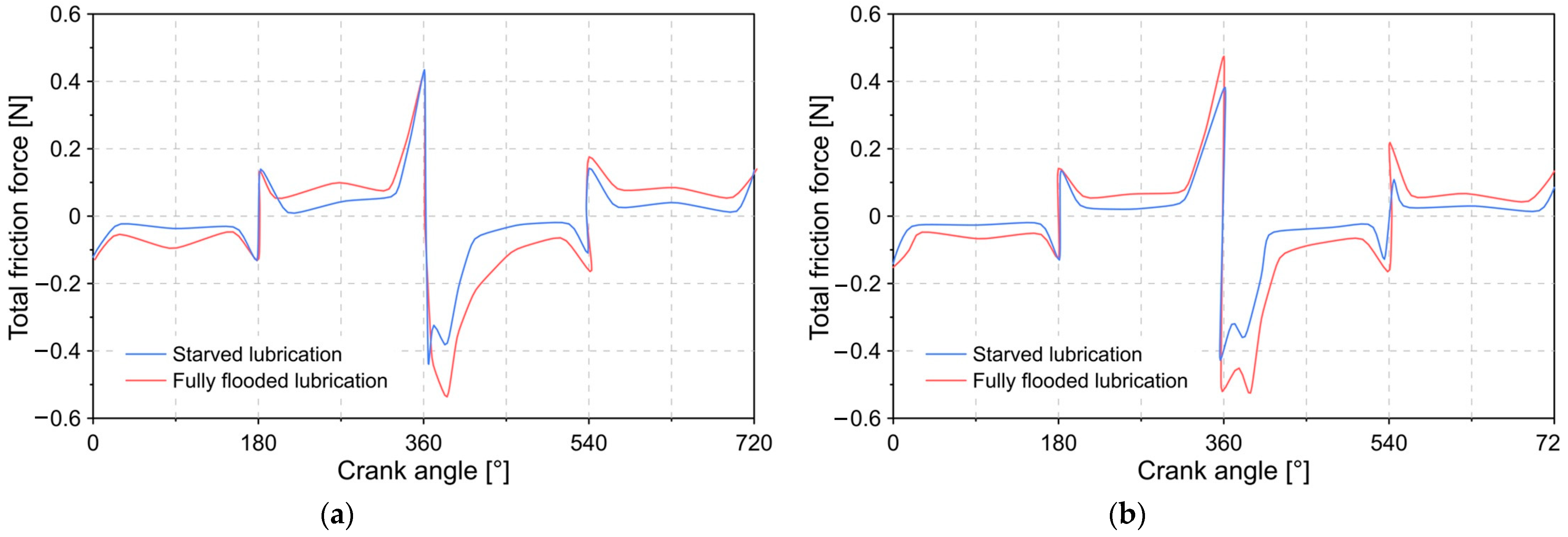
4.4. Effect of Lubrication Condition

To evaluate the impact of the lubrication condition, the minimum oil film thickness, the total friction force, and the power loss for a starved lubrication condition and fully flooded lubrication were analyzed (see Figure 11). The obtained results are shown next.
The results of Figure 12 show that the MOFT estimate is higher when considering a starved lubrication condition. For the established conditions, maximum MOFT of 1.21 and 1.32 μ m were observed under a fully flooded lubrication and starved lubrication and untextured surface. For a condition with a textured surface on the cylinder liner, maximum MOFT of 1.33 and 1.39 μ m were recorded under fully flooded lubrication and starved lubrication.
The change in the thickness of the lubrication film implies a variation in the total friction force, as shown in Figure 13, in which it was observed that the magnitude of the friction force tends to be greater along the combustion cycle under a fully flooded lubrication condition.
The effect of the change in lubrication condition for power loss is shown in Figure 14. In general, it was observed that when establishing a fully flooded condition, the estimate of the loss power is greater, which is a consequence of the greater role of the asperity contact force, the force caused by the viscosity of the lubricant. This increase in loss power was most evident during the final compression stage, which shows an increase of 44%.

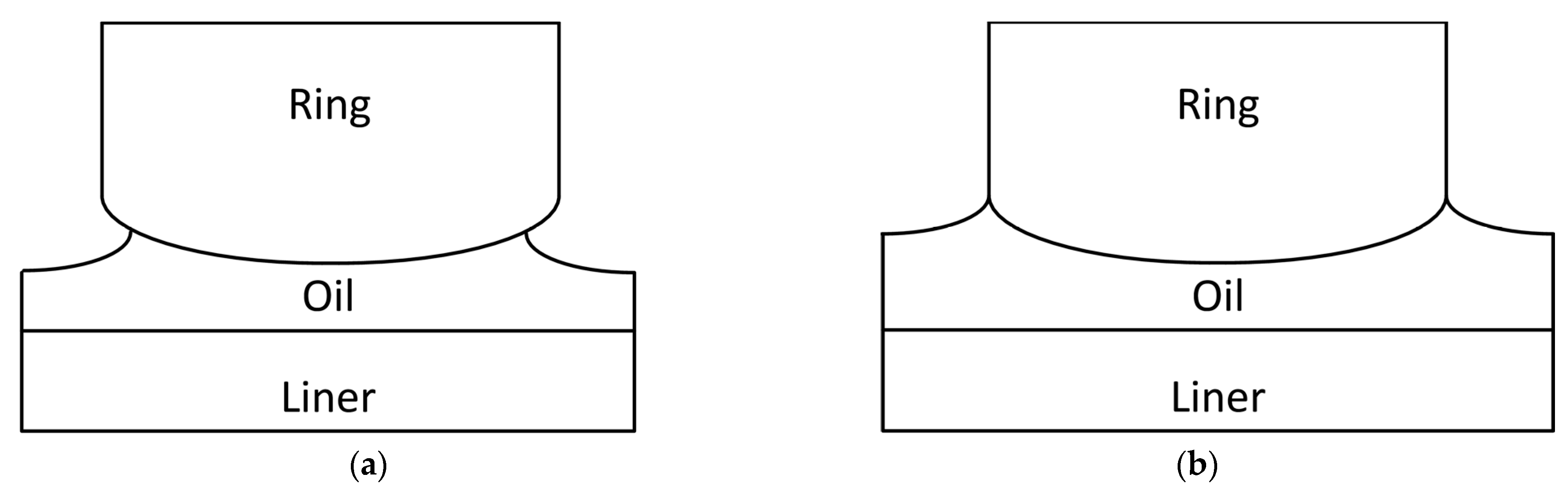
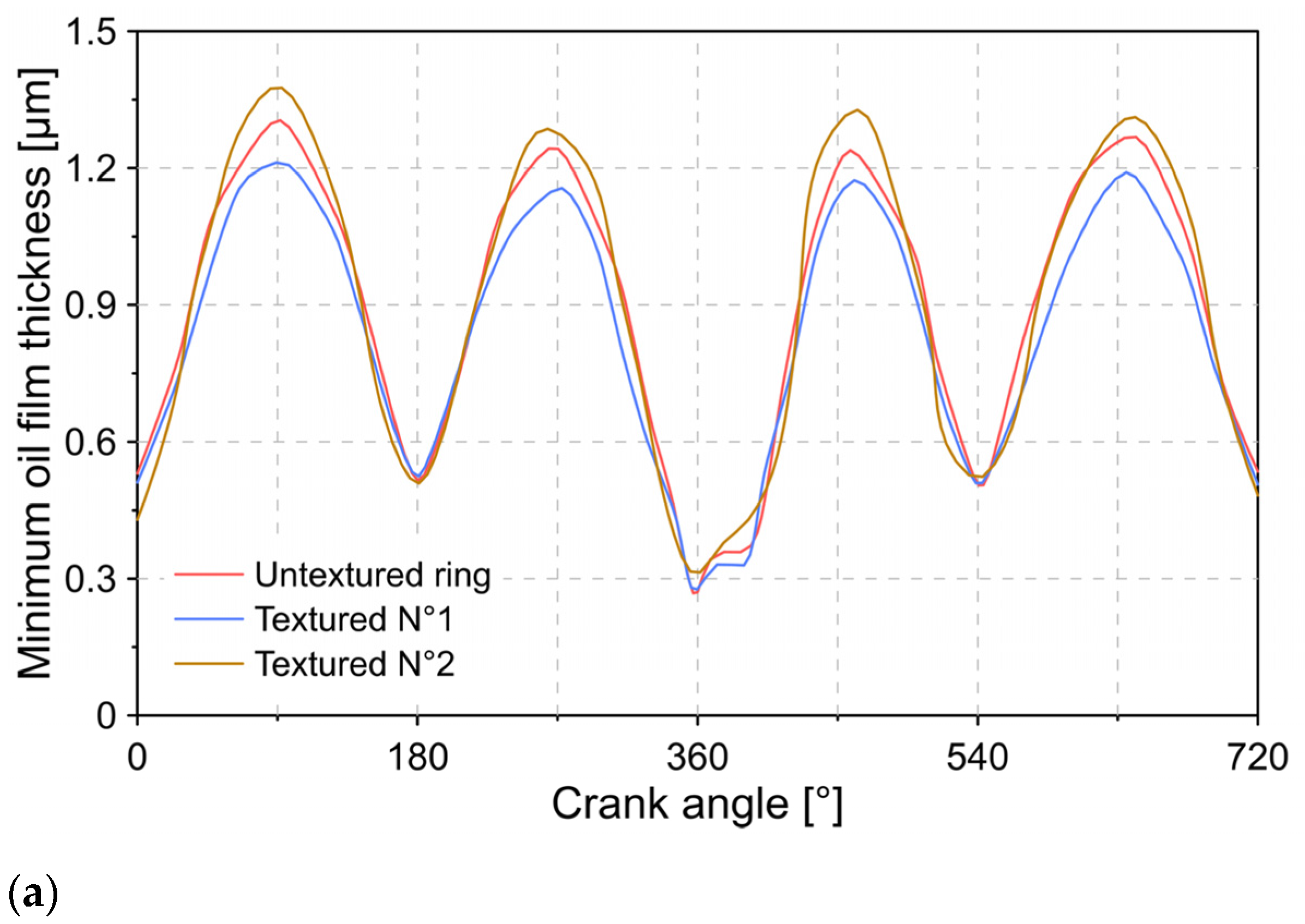
4.5. Ring Surface Texture Effect

Changes in surface texture need not be limited to the cylinder liner. The modification in the texture can also be applied to the profile of the piston ring. To evaluate the influence of this modification, two different configurations of surface texture are established, which are described in Table 4.
Figure 15 shows the influence of the ring surface texture on the MOFT and the total power loss, maintaining a surface texture on the cylinder liner. The results show that the application of texture N°2 caused an increase in the MOFT and a reduction in the total power loss. A negative impact was observed with the geometric characteristics of texture N°1, which is reflected in a lower MOFT and an increase in power loss.

5. Discussion

The results described in Figure 6 demonstrate that the presence of a textured surface on the cylinder liner causes a variation in the dynamic characteristics between the contact of the piston ring and the cylinder liner. This can be a consequence of the pocket effect of the applied texture, which causes an increase in the thickness of the lubrication film and, therefore, a change in the pressure conditions. This is mainly reflected in a decrease in the asperity contact force and in the total friction force, in which reductions of 9.43% and 5.29% were registered in the maximum magnitude of these forces. In the case of the force of combustion gases, no obvious change in its trend was observed. For the hydrodynamic force, the results indicate an increase when the surface texture is applied. The maximum increase observed in the hydrodynamic force was 11%, which occurred during the final stage of the compression cycle. This behavior can be attributed to the increase in the thickness of the lubrication film.
The analysis developed shows that the application of a texture on the surface of the cylinder liner allows an increase in MOFT during the combustion cycle. This is attributed to the reduction in the asperity contact force, as shown in Figure 7b. This occurs as a consequence of the reduction of the contact area with the ring surface due to the presence of the texture. The positive effect of the textured surface is evidenced by evaluating the total power loss. The results show that the surface texture allows the power loss to be reduced by 7%.
The results described in Figure 12, Figure 13 and Figure 14 demonstrate that the lubrication condition has a considerable impact on the estimates of the lubricant characteristics. In general, a fully flooded lubrication condition causes a lower estimate in the MOFT. This is attributed to the higher friction forces that this lubrication condition produces compared to a starved lubrication condition (see Figure 13). This may be the consequence of the lower support force exerted by the combustion gases on the profile of the piston ring, resulting in a reduction in the clearance between the cylinder liner and the ring surface. Reducing this clearance implies an increase in the asperity and viscosity forces of the lubricant. In general, a fully flooded lubrication condition estimates a reduction in MOFT by 8% compared to a starved condition. The results describe a maximum magnitude of 0.47 and 0.38 N in the total friction force for a fully flooded and starved lubrication condition, respectively.
Another possible alternative to reduce power loss is the application of a textured surface on the piston ring. The results demonstrate that the proper selection of the geometry of a texture in the ring allows an 11% reduction in power loss. However, this percentage of power loss reduction has the potential to increase since the textured surface of the ring profile depends on different geometric characteristics. Therefore, it is necessary to study an optimization analysis focused on this surface to guarantee a maximum reduction in power loss.

6. Conclusions

In the present investigation, the influence of a textured surface on the lubrication characteristics between the cylinder liner and the profile of the piston ring was studied. The analysis focused on the different types of dynamic forces, minimum oil film thickness, and power loss. Additionally, the effect of the lubrication condition (starved lubrication and fully flooded lubrication) was studied.
The presence of a textured surface on the cylinder liner made it possible to obtain a reduction of 9.43% and 5.29% in the maximum magnitude of the asperity contact force and in the total friction force. This is due to the smaller contact area between the cylinder liner and the profile of the piston ring. Additionally, the textured surface allowed for achieving a greater thickness in the lubrication film, which allowed for reducing the wear process. In general, it was observed that the presence of the textured surface allowed a 4% increase in MOFT. In this way, it is possible to reduce power loss.
The results show that establishing a fully flooded lubrication condition produces an overestimation in the total friction force. This is the main consequence of the lower support that the gases can exert on the ring profile. This implies a greater magnitude in the total friction force and, therefore, in the estimated power loss.
The analysis of the results shows that the implementation of a textured surface in the profile of the ring can cause an increase of 5% in the MOFT. This implies a reduction in power loss. The results indicate that an 11% reduction in power loss is possible. However, it is necessary to develop a rigorous study to identify the characteristics of the optimal textured surface since an inadequate surface texture in the ring can cause a decrease of 7% in MOFT and an increase of 9% in the loss of power.
The implemented numerical model contributes to the development of more complex studies focused on the analysis of tribological characteristics under the influence of textured surfaces due to the consideration of poor lubrication, which is more consistent with the actual operating conditions of the engine. In this way, it seeks to support the search for improvements in engine performance.

Author Contributions

Conceptualization, C.P.G.; Methodology, J.P.R., C.P.G., and S.O.A.; Software, J.P.R., and C.P.G.; Validation, J.P.R., and C.P.G.; Formal analysis, J.P.R., C.P.G., and S.O.A.; Investigation, J.P.R., C.P.G., and S.O.A.; Resources, J.P.R., and S.O.A.; Writing—Original Draft Preparation, C.P.G.; Writing—Review and Editing, S.O.A.; Funding acquisition, J.P.R., and S.O.A. All authors have read and agreed to the published version of the manuscript.

Funding

This research received no external funding.

Institutional Review Board Statement

Not applicable.

Informed Consent Statement

Not applicable.

Data Availability Statement

Data sharing not applicable.

Acknowledgments

The authors would like to acknowledge the Universidad Francisco de Paula Santander for their support in the development of this investigation.

Conflicts of Interest

The authors declare no conflict of interest.

Abbreviations

The following abbreviations are used in this manuscript:
Nomenclature
ICInternal combustion
JFOJakobsson Floberg Olsson
MOFTMinimum oil film thickness
c t Thermal expansion coefficient
T Temperature
P Pressure
s Thermo-viscosity indices
z Lubricant piezo-viscosity
μ , c p Model constants
v p Piston velocity
h Lubrication film thickness.
r Crank-pin radius
l Connecting rod length
h m Minimum oil film thickness
hlHeight of the groove
h s Height of the ring profile
h g Average groove depth
b Width of ring face
F g a s Force produced by the pressure of the gas
F c Compression force
F a s p Asperity contact force
F h y d Hydrodynamic force
D Diameter
σ t Bending stress
E Modulus of elasticity
L Ring length
f Ring gap
E Effective Young’s modulus of elasticity
A Area of contact
F 5 / 2 Statistical function
F t f Total friction force
A e Real area of contact
F 2 Statistical function of the Stribeck’s lubricant film ratio
W ˙ l o s s Power loss
Greek Letters
ρ Density
μ Viscosity
α o Piezo-viscosity
γ o Thermo-viscosity
σ Composite roughness
ϕ c ,   ϕ s , ϕ x Flow factors
ω Crankshaft angular velocity
θ Crank angle
δ Crown height of the ring
κ Average asperity tip radius of curvature
ς Composite surface roughness
ξ Asperity distribution per unit contact area.
ν Poisson’s ratio
λ Stribeck’s lubricant film ratio
τ Viscous shear stress
τ o Limiting Eyring shear stress
ζ Coefficient of asperity shear strength

References

  1. De La Hoz, J.S.; Valencia, G.; Forero, J.D. Reynolds Averaged Navier–Stokes Simulations of the Airflow in a Centrifugal Fan Using OpenFOAM. Int. Rev. Model. Simul. 2019, 12, 230–242. [Google Scholar] [CrossRef]
  2. Orozco, T.; Herrera, M.; Forero, J.D. CFD Study of Heat Exchangers Applied in Brayton Cycles: A Case Study in Supercritical Condition Using Carbon Dioxide as Working Fluid. Int. Rev. Model. Simul. 2019, 12, 72–82. [Google Scholar] [CrossRef]
  3. Dolatabadi, N.; Forder, M.; Morris, N.; Rahmani, R.; Rahnejat, H.; Howell-Smith, S. Influence of advanced cylinder coatings on vehicular fuel economy and emissions in piston compression ring conjunction. Appl. Energy 2020, 259, 114129. [Google Scholar] [CrossRef]
  4. Orozco, W.; Acuña, N.; Forero, J.D. Characterization of Emissions in Low Displacement Diesel Engines Using Biodiesel and Energy Recovery System. Int. Rev. Mech. Eng. 2017, 13, 420–426. [Google Scholar] [CrossRef]
  5. Exxon Mobil Corporation. Exxon Mobil Corporation Report: Outlook for Energy: A View to 2040. 2017. Available online: https://cdn.exxonmobil.com/~/media/global/files/outlook-for-energy/2017/2017-outlook-for-energy.pdf (accessed on 12 January 2021).
  6. Escobar-Yonoff, R.; Maestre-Cambronel, D.; Charry, S.; Rincón-Montenegro, A.; Portnoy, I. Performance assessment and economic perspectives of integrated PEM fuel cell and PEM electrolyzer for electric power generation. Heliyon 2021, 7, e06506. [Google Scholar] [CrossRef]
  7. Roberts, A.; Brooks, R.; Shipway, P. Internal combustion engine cold-start efficiency: A review of the problem, causes and potential solutions. Energy Convers. Manag. 2014, 82, 327–350. [Google Scholar] [CrossRef] [Green Version]
  8. Forero, J.D.; Taborda, L.L.; Silvera, A.B. Characterization of the Performance of Centrifugal Pumps Powered by a Diesel Engine in Dredging Applications. Int. Rev. Mech. Eng. 2019, 13, 11–20. [Google Scholar] [CrossRef]
  9. Rahnejat, H. Tribology and Dynamics of Engine and Powertrain: Fundamentals Applications and Future Trends; Woodhead Publishing: Cambridge, UK, 2010. [Google Scholar]
  10. Ochoa, G.V.; Rojas, J.P.; Forero, J.D. Advance Exergo-Economic Analysis of a Waste Heat Recovery System Using ORC for a Bottoming Natural Gas Engine. Energies 2020, 13, 267. [Google Scholar] [CrossRef] [Green Version]
  11. Richardson, D.E. Review of Power Cylinder Friction for Diesel Engines. J. Eng. Gas Turbines Power 2000, 122, 506–519. [Google Scholar] [CrossRef]
  12. Sun, J.; Zhu, J.; Wang, H.; Zhao, X.; Teng, Q.; Ren, Y.; Zhu, G.; Zhang, X.; Gao, Y. Research on the influence of the lubrication status at the inlet on the lubrication characteristics of engine piston ring. Lubr. Sci. 2020, 32, 321–332. [Google Scholar] [CrossRef]
  13. Alibaba, M.; Pourdarbani, R.; Manesh, M.H.K.; Ochoa, G.V.; Forero, J.D. Thermodynamic, exergo-economic and exergo-environmental analysis of hybrid geothermal-solar power plant based on ORC cycle using emergy concept. Heliyon 2020, 6, e03758. [Google Scholar] [CrossRef] [PubMed]
  14. Duarte, J.; Garcia, J.; Jiménez, J.; Sanjuan, M.E.; Bula, A.; González, J. Auto-Ignition Control in Spark-Ignition Engines Using Internal Model Control Structure. J. Energy Resour. Technol. 2017, 139, 022201. [Google Scholar] [CrossRef]
  15. Ochoa, G.V.; Isaza-Roldan, C.; Forero, J.D. Thermoeconomic analysis of different exhaust waste-heat recovery systems for natural gas engine based on ORC Rankine Cycle under Organic Fluids with Low Global Warming Potential. Energies 2020, 13, 1317. [Google Scholar] [CrossRef] [Green Version]
  16. Consuegra, F.; Bula, A.; Guillín, W.; Sánchez, J.; Forero, J.D. Instantaneous in-Cylinder Volume Considering Deformation and Clearance due to Lubricating Film in Reciprocating Internal Combustion Engines. Energies 2019, 12, 1437. [Google Scholar] [CrossRef] [Green Version]
  17. Obregon, L.; Valencia, G.; Forero, J.D. Efficiency Optimization Study of a Centrifugal Pump for Industrial Dredging Applications Using CFD. Int. Rev. Model. Simul. 2019, 12, 245–252. [Google Scholar] [CrossRef]
  18. Ochoa, G.V.; Gutierrez, J.C.; Forero, J.D. Exergy, Economic, and Life-Cycle Assessment of ORC System for Waste Heat Recovery in a Natural Gas Internal Combustion Engine. Resources 2020, 9, 2. [Google Scholar] [CrossRef] [Green Version]
  19. Ma, Z.; Henein, N.A.; Bryzik, W. A Model for Wear and Friction in Cylinder Liners and Piston Rings. Tribol. Trans. 2006, 49, 315–327. [Google Scholar] [CrossRef]
  20. Hernández-Comas, B.; Maestre-Cambronel, D.; Pardo-García, C.; Fonseca-Vigoya, M.; Pabón-León, J. Influence of Compression Rings on the Dynamic Characteristics and Sealing Capacity of the Combustion Chamber in Diesel Engines. Lubricants 2021, 9, 25. [Google Scholar] [CrossRef]
  21. Baker, C.; Theodossiades, S.; Rahmani, R.; Rahnejat, H.; Fitzsimons, B. On the Transient Three-Dimensional Tribodynamics of Internal Combustion Engine Top Compression Ring. J. Eng. Gas Turbines Power 2017, 139, 062801. [Google Scholar] [CrossRef]
  22. Rahmani, R.; Rahnejat, H.; Fitzsimons, B.; Dowson, D. The effect of cylinder liner operating temperature on frictional loss and engine emissions in piston ring conjunction. Appl. Energy 2017, 191, 568–581. [Google Scholar] [CrossRef] [Green Version]
  23. Mishra, P.C.; Balakrishnan, S.; Rahnejat, H. Tribology of compression ring-to-cylinder contact at reversal. Proc. Inst. Mech. Eng. Part J J. Eng. Tribol. 2008, 222, 815–826. [Google Scholar] [CrossRef] [Green Version]
  24. Mishra, P.C. Tribodynamic modeling of piston compression ring and cylinder liner conjunction in high-pressure zone of engine cycle. Int. J. Adv. Manuf. Technol. 2013, 66, 1075–1085. [Google Scholar] [CrossRef]
  25. Rahmani, R.; Theodossiades, S.; Rahnejat, H.; Fitzsimons, B. Transient elastohydrodynamic lubrication of rough new or worn piston compression ring conjunction with an out-of-round cylinder bore. Proc. Inst. Mech. Eng. Part J J. Eng. Tribol. 2012, 226, 284–305. [Google Scholar] [CrossRef] [Green Version]
  26. Morris, N.; Rahmani, R.; Rahnejat, H.; King, P.D.; Fitzsimons, B. Tribology of piston compression ring conjunction under transient thermal mixed regime of lubrication. Tribol. Int. 2013, 59, 248–258. [Google Scholar] [CrossRef] [Green Version]
  27. Fatjo, G.G.A.; Smith, E.; Sherrington, I. Mapping lubricating film thickness, film extent and ring twist for the compression-ring in a firing internal combustion engine. Tribol. Int. 2014, 70, 112–118. [Google Scholar] [CrossRef]
  28. Checo, H.M.; Ausas, R.F.; Jai, M.; Cadalen, J.P.; Choukroun, F.; Buscaglia, G.C. Moving textures: Simulation of a ring sliding on a textured liner. Tribol. Int. 2014, 72, 131–142. [Google Scholar] [CrossRef]
  29. Hu, Y.; Meng, X.; Xie, Y. A new efficient flow continuity lubrication model for the piston ring-pack with consideration of oil storage of the cross-hatched texture. Tribol. Int. 2018, 119, 443–463. [Google Scholar] [CrossRef]
  30. Priest, M.; Dowson, D.; Taylor, C.M. Theoretical modelling of cavitation in piston ring lubrication. Proc. Inst. Mech. Eng. Part C J. Mech. Eng. Sci. 2000, 214, 435–447. [Google Scholar] [CrossRef]
  31. Richardson, D.E.; Borman, G.L. Theoretical and Experimental Investigations of Oil Films for Application to Piston Ring Lubrication. Sae Tech. Pap. Ser. 1992, 936, 922341. [Google Scholar] [CrossRef]
  32. Ma, M.T.; Sherrington, I.; Smith, E.H. Implementation of an Algorithm to Model the Starved Lubrication of a Piston Ring in Distorted Bores: Prediction of Oil Flow and Onset of Gas Blow-By. Proc. Inst. Mech. Eng. Part J J. Eng. Tribol. 1996, 210, 29–44. [Google Scholar] [CrossRef]
  33. Tian, T.; Wong, V.W.; Heywood, J.B. A Piston Ring-Pack Film Thickness and Friction Model for Multigrade Oils and Rough Surfaces. Sae Trans. 1996, 1783–1795. [Google Scholar] [CrossRef]
  34. Ochoa, G.V.; Isaza-Roldan, C.; Forero, J.D. A phenomenological base semi-physical thermodynamic model for the cylinder and exhaust manifold of a natural gas 2-megawatt four-stroke internal combustion engine. Heliyon 2019, 5, e02700. [Google Scholar] [CrossRef] [Green Version]
  35. Diaz, G.A.; Forero, J.D.; Garcia, J.; Rincon, A.; Fontalvo, A.; Bula, A.J.; Padilla, R.V. Maximum Power from Fluid Flow by Applying the First and Second Laws of Thermodynamics. J. Energy Resour. Technol. 2017, 139, 032903. [Google Scholar] [CrossRef]
  36. Valencia, G.; Duarte, J.; Isaza-Roldan, C. Thermoeconomic Analysis of Different Exhaust Waste-Heat Recovery Systems for Natural Gas Engine Based on ORC. Appl. Sci. 2019, 9, 4017. [Google Scholar] [CrossRef] [Green Version]
  37. Morris, N.; Mohammadpour, M.; Rahmani, R.; Johns-Rahnejat, P.M.; Rahnejat, H.; Dowson, D. Effect of cylinder deactivation on tribological performance of piston compression ring and connecting rod bearing. Tribol. Int. 2018, 120, 243–254. [Google Scholar] [CrossRef]
  38. Saidur, R.; Rezaei, M.; Muzammil, W.K.; Hassan, M.H.; Paria, S.; Hasanuzzaman, M. Technologies to recover exhaust heat from internal combustion engines. Renew. Sustain. Energy Rev. 2012, 16, 5649–5659. [Google Scholar] [CrossRef]
  39. Liu, Z.; Meng, X.; Wen, C.; Yu, S.; Zhou, Z. On the oil-gas-solid mixed bearing between compression ring and cylinder liner under starved lubrication and high boundary pressures. Tribol. Int. 2019, 140, 105869. [Google Scholar] [CrossRef]
  40. Babu, P.V.; Syed, I.; BenBeera, S. Experimental investigation on effects of positive texturing on friction and wear reduction of piston ring/cylinder liner system. Mater. Today Proc. 2020, 24, 1112–1121. [Google Scholar] [CrossRef]
  41. Vlădescu, S.-C.; Ciniero, A.; Tufail, K.; Gangopadhyay, A.; Reddyhoff, T. Looking into a laser textured piston ring-liner contact. Tribol. Int. 2017, 115, 140–153. [Google Scholar] [CrossRef]
  42. Patil, A.S.; Shirsat, U. Effect of laser textured dimples on tribological behavior of piston ring and cylinder liner contact at varying load. Mater. Today Proc. 2021, 44, 1005–1020. [Google Scholar] [CrossRef]
  43. Ezhilmaran, V.; Vasa, N.; Vijayaraghavan, L. Investigation on generation of laser assisted dimples on piston ring surface and influence of dimple parameters on friction. Surf. Coat. Technol. 2018, 335, 314–326. [Google Scholar] [CrossRef]
  44. Koszela, W.; Pawlus, P.; Reizer, R.; Liskiewicz, T. The combined effect of surface texturing and DLC coating on the functional properties of internal combustion engines. Tribol. Int. 2018, 127, 470–477. [Google Scholar] [CrossRef]
  45. Grabon, W.; Koszela, W.; Pawlus, P.; Ochwat, S. Improving tribological behaviour of piston ring-cylinder liner frictional pair by liner surface texturing. Tribol. Int. 2013, 61, 102–108. [Google Scholar] [CrossRef]
  46. Babu, P.V.; Ismail, S.; Ben, B.S. Experimental and numerical studies of positive texture effect on friction reduction of sliding contact under mixed lubrication. Proc. Inst. Mech. Eng. Part J J. Eng. Tribol. 2021, 235, 360–375. [Google Scholar] [CrossRef]
  47. Mishra, P.; Ramkumar, P. Effect of Micro Texture on Tribological Performance of Piston Ring-Cylinder Liner System under Different Lubrication Regimes. Sae Tech. Pap. 2018, 28, 52. [Google Scholar] [CrossRef]
  48. Mishra, P.; Ramkumar, P. Effect of additives on a surface textured piston ring-cylinder liner system. Tribol. Mater. Surf. Interfaces 2019, 13, 67–75. [Google Scholar] [CrossRef]
  49. Dowson, D.; Higginson, G.R. A Numerical Solution to the Elasto-Hydrodynamic Problem. J. Mech. Eng. Sci. 1959, 1, 6–15. [Google Scholar] [CrossRef]
  50. Roelands, C.J.A.; Winer, W.O.; Wright, W.A. Correlational Aspects of the Viscosity-Temperature-Pressure Relationship of Lubricating Oils (Dr In dissertation at Technical University of Delft, 1966). J. Lubr. Technol. 1971, 93, 209–210. [Google Scholar] [CrossRef] [Green Version]
  51. Houpert, L. New Results of Traction Force Calculations in Elastohydrodynamic Contacts. J. Tribol. 1985, 107, 241–245. [Google Scholar] [CrossRef]
  52. Patir, N.; Cheng, H.S. An Average Flow Model for Determining Effects of Three-Dimensional Roughness on Partial Hydrodynamic Lubrication. J. Lubr. Technol. 1978, 100, 12–17. [Google Scholar] [CrossRef]
  53. Patir, N.; Cheng, H.S. Application of Average Flow Model to Lubrication Between Rough Sliding Surfaces. J. Lubr. Technol. 1979, 101, 220–229. [Google Scholar] [CrossRef]
  54. Chong, W.; Howell-Smith, S.; Teodorescu, M.; Vaughan, N. The influence of inter-ring pressures on piston-ring/liner tribological conjunction. Proc. Inst. Mech. Eng. Part J J. Eng. Tribol. 2012, 227, 154–167. [Google Scholar] [CrossRef]
  55. Tamminen, J.; Sandström, C.-E.; Nurmi, H. Influence of the Piston Inter-ring Pressure on the Ring Pack Behaviour in a Medium Speed Diesel Engine. SAE Tech. Pap. 2005, 3847, 1–13. [Google Scholar] [CrossRef]
  56. Lyubarskyy, P.; Bartel, D. 2D CFD-model of the piston assembly in a diesel engine for the analysis of piston ring dynamics, mass transport and friction. Tribol. Int. 2016, 104, 352–368. [Google Scholar] [CrossRef]
  57. Makartchouk, A. Diesel Engine Engineering: Thermodynamics, Dynamics, Design, and Control; CRC Press: Boca Raton, FL, USA, 2002. [Google Scholar]
  58. Greenwood, J.A.; Tripp, J.H. The Contact of Two Nominally Flat Rough Surfaces. Proc. Inst. Mech. Eng. 1970, 185, 625–633. [Google Scholar] [CrossRef]
  59. Teodorescu, M.; Balakrishnan, S.; Rahnejat, H. Integrated Tribological Analysis within a Multi- physics Approach to System Dynamics. Tribol. Interface Eng. Ser. 2005, 48, 725–737. [Google Scholar] [CrossRef]
  60. Styles, G.; Rahmani, R.; Rahnejat, H.; Fitzsimons, B. In-cycle and life-time friction transience in piston ring–liner conjunction under mixed regime of lubrication. Int. J. Engine Res. 2014, 15, 862–876. [Google Scholar] [CrossRef] [Green Version]
  61. Uras, H.M.; Patterson, D.J. Effect of Some Lubricant and Engine Variables on Instantaneous Piston and Ring Assembly Friction. Sae Trans. 1984, 918–931. [Google Scholar] [CrossRef]
  62. Turnbull, R.; Dolatabadi, N.; Rahmani, R.; Rahnejat, H. An assessment of gas power leakage and frictional losses from the top compression ring of internal combustion engines. Tribol. Int. 2020, 142, 105991. [Google Scholar] [CrossRef]
Figure 1. Lubrication film thickness for microtextured surface.
Lubricants 09 00051 g001
Figure 2. (a) Diagram of dynamic forces in the piston ring and (b) reference pressure conditions.
Lubricants 09 00051 g002
Figure 3. Numerical model methodology.
Lubricants 09 00051 g003
Figure 4. Diagram of the measurement system.
Lubricants 09 00051 g004
Figure 5. (a) Comparison between the friction force obtained experimentally vs. numerical model and (b) convergence analysis of the numerical model.
Lubricants 09 00051 g005
Figure 6. Hydrodynamic pressure distribution under starved lubrication condition for (a) untextured surface and (b) textured surface.
Lubricants 09 00051 g006aLubricants 09 00051 g006b
Figure 7. Distribution of (a) hydrodynamic force, (b) asperity contact force, and (c) gas force during the combustion cycle under starved lubrication condition.
Lubricants 09 00051 g007aLubricants 09 00051 g007b
Figure 8. Minimum oil film thickness under starved lubrication condition.
Lubricants 09 00051 g008
Figure 9. Total friction force during a combustion cycle under starved lubrication condition.
Lubricants 09 00051 g009
Figure 10. Total power loss during a combustion cycle under starved lubrication condition.
Lubricants 09 00051 g010
Figure 11. Lubrication conditions: (a) starved lubrication and (b) fully flooded lubrication.
Lubricants 09 00051 g011
Figure 12. Effect of lubrication condition on minimum oil film thickness for (a) untextured surface and (b) textured surface.
Lubricants 09 00051 g012
Figure 13. Effect of lubrication condition on total friction force for (a) untextured surface and (b) textured surface.
Lubricants 09 00051 g013
Figure 14. Effect of lubrication condition on total power loss for (a) untextured surface and (b) textured surface.
Lubricants 09 00051 g014
Figure 15. Effect of piston ring surface texture in (a) minimum oil film thickness and (b) total power loss under starved lubrication condition.
Lubricants 09 00051 g015aLubricants 09 00051 g015b
Table 1. Reference engine parameters.
ParameterValue
Crankshaft radius48 mm
Length connecting rod106 mm
Piston radius39 mm
Speed 3600 rpm
Piston mass 0.305 kg
Bore78 mm
Stroke62.57 mm
Properties lubrication oil (SAE15W-40)Value
Density at 20 °C 0.864 g/cm3
Viscosity at 40 °C91.76 mm2/s
Flashpoint224 °C
Pour point−33 °C
Table 2. Characteristic of the textured surface on the cylinder liner.
ParameterValue
Depth of groove1.2 μ m
Radius of groove25 μ m
Distance between groove150 μ m
Table 3. Measuring instruments.
Instrument ManufacturerRangeUncertainty (%)
Piezoelectric transducer Kistler type 7063-A0–250 bar ± 0.5
Angle sensorBeck Arnley 180-04205–9999 rpm ± 1.0
Strain gauges sensorKFG-1-120-D16-11L1M2S0–50,000 μϵ ± 0.5
Strain Gauges Sensor
Maximum strain 50,000 μ ϵ
Fatigue>10,000,000 cycles
Substrate thickness15 μ m
Cover thickness9 μ m
Gage factor 2.1
Table 4. Characteristics of the textured surface on the compression ring.
TextureParameterValue
N°1Depth of groove1 μ m
Radius of groove50 μ m
Distance between groove200 μ m
N°2Depth of groove1.25 μ m
Radius of groove50 μ m
Distance between groove100 μ m
Publisher’s Note: MDPI stays neutral with regard to jurisdictional claims in published maps and institutional affiliations.

